

Abstract
Finite element methods have been applied extensively and with much success in the analysis of orthopaedic implants.6,7,12,13,15 Recently a growing interest has developed, in the orthopaedic biomechanics community, in how numerical models can be constructed for the optimal solution of problems in contact mechanics. New developments in this area are of paramount importance in the design of improved implants for orthopaedic surgery. Finite element and other computational techniques are widely applied in the analysis and design of hip and knee implants, with additional joints (ankle, shoulder, wrist) attracting increased attention.
The objective of this investigation was to develop a simplified adaptive meshing scheme to facilitate the finite element analysis of a dual-curvature total wrist implant. Using currently available software, the analyst has great flexibility in mesh generation, but must prescribe element sizes and refinement schemes throughout the domain of interest. Unfortunately, it is often difficult to predict in advance a mesh spacing that will give acceptable results. Adaptive finite-element mesh capabilities1,14 operate to continuously refine the mesh to improve accuracy where it is required, with minimal intervention by the analyst. Such mesh adaptation generally means that in certain areas of the analysis domain, the size of the elements is decreased (or increased) and/or the order of the elements may be increased (or decreased). In concept, mesh adaptation is very appealing. Although there have been several previous applications of adaptive meshing for in-house FE codes, we have coupled an adaptive mesh formulation with the pre-existing commercial programs PATRAN (MacNeal-Schwendler Corp., USA) and ABAQUS (Hibbit Karlson and Sorensen, Pawtucket, RI). In doing so, we have retained several attributes of the commercial software, which are very attractive for orthopaedic implant applications.
INTRODUCTION
Finite element analysis was first introduced to the field of orthopaedics in 1972.3 Since that time, finite element models have been increasingly used for three main purposes: (i) for design and pre-clinical analysis of prostheses; (ii) to obtain fundamental knowledge about musculoskeletal structures; and (iii) to investigate time-dependent adaptation processes (i.e., tissue growth, remodeling and degeneration) in tissues.11 Successful three-dimensional finite element modeling has been applied to several different prostheses such as the hip4,9,10,12, the knee8, the metacarpophalangeal joint16, and the shoulder.2
The analysis of dislocation biomechanics relies heavily on the principles of contact mechanics. Inherently nonlinear, contact problems are difficult to solve. For dislocation problems, in particular, this is further compounded by the highly localized regions of contact. Recently, a growing interest has developed in the orthopaedic biomechanics community in how numerical models can be constructed for the solution of problems in implant contact mechanics. The finite element method has proven a successful tool for such analyses. Scifert et al.12, for example, developed a three-dimensional nonlinear finite element model for the purpose of studying dislocation of total hip arthroplasty. With this approach, they were able to identify component design modifications that had an increased resistance to dislocation.
FINITE ELEMENT METHODS
Basic to any finite element (FE) task is the geometric discretization of the structure(s) of interest, a process known as mesh generation. The creation of adequate finite-element models for complex structural configurations can be time-consuming. Powerful software tools for mesh generation are commercially available, the limits of which are well understood: PATRAN, (MacNeal-Schwendler Corp., USA), ANSYS (Ansys Inc., Canonsburg, PA), TrueGrid (XYZ Scientific Applications, Inc., Livermore, CA, etc.). Using currently available software, the analyst has great flexibility in meshing, but must prescribe element sizes and refinement throughout the domain. Simplifying assumptions must be made to keep the FE models manageable, not only from the perspective of the complex geometries, but moreover in view of the computational tractability. Prior to accepting the results of a finite element analysis, both the accuracy and validity of the solution must be objectively established.3 The accuracy of the analysis reflects how well the chosen element types and mesh can approximate the exact solution for the structure, given the assumed simplifying assumptions. The most important factor in establishing accuracy is the element mesh density, in relation to the element type chosen. An objective assessment of the mesh density is typically achieved via a convergence test (i.e., repeated calculations for increased mesh refinement and checking the convergence of a desired parameter; for example, stress). For contact as well as all other types of analyses the solution asymptotically improves as the mesh is refined.
For well-behaved problems, a grid of uniform mesh spacing (in each of the coordinate directions) usually gives satisfactory results. However, there are classes of problems where convergence is more problematic in some regions (due to contact stress concentrations, etc.) than in others. In principle a uniform grid, having spacing fine enough so that the local errors estimated in these difficult regions are acceptable, could be adopted. In practice, such an approach is prohibitively costly computationally. Furthermore, for problems with a spatially migrating contact zone, it is difficult to predict in advance a mesh spacing that will give acceptable results. To reduce engineering time expended in model development, adaptive finite-element mesh capabilities have been recently introduced, offering the capability to continuously refine the mesh to improve accuracy where required. Adaptive meshing for contact problems, however, is in the formative development stage. The majority of adaptive meshing algorithms have, to our knowledge, been employed in theoretical pursuits and applied to simplified geometries. Simple geometries, however, are of little value for the applications currently confronted in orthopaedics.
Several researchers are devoted to the development of adaptive refinement strategies for effective finite element analyses.5 These include methods such as the adaptive h-refinement techniques, p-refinement techniques, and hp-refinement techniques. The h-refinement technique enhances the mesh, by subdividing the elements, while retaining the order of the elements. The adaptive p-methods raise the order of the interpolation functions while preserving the same mesh. A combination of the two methods yields the hp-refinement technique, thereby enriching the mesh by reducing the size of the elements, while simultaneously raising the order of the elements. If these strategies are employed for the refinement of localized regions the use of either distorted transition grids, specialized transition elements, or multi-point constraints is inevitable. While multiple point constraints tend to be cumbersome from a model development standpoint, distorted elements in the transition zones tend to significantly degrade the accuracy of the results.
Our immediate impetus for pursuing adaptive mesh refinement arose due to challenges encountered when modeling dislocations in an otherwise promising class of total wrist implants, the Universal (Kinetikos Medical, Inc., San Diego, CA) total wrist. Computer Aided Design (Pro/ENGINEER, PTC, Needham, MA) capabilities were used to model the Universal prosthesis based on the manufacturer's dimensional specifications (Figure 1). The model was imported into the solid modeler PATRAN, enabling a base finite element mesh to be generated for each component. The polyethylene carpal component (Figure 2) was modeled as a nonlinear deformable body with an elastic modulus (E) of 634.92 MPa and Poisson ratio of 0.45. Six thousand four hundred eight-noded hexahedral elements were used in the original coarse mesh of the polyethylene component. The elastic modulus of the CoCr and Ti alloys are significantly greater than that of ultrahigh molecular weight polyethylene (UHMWPE). As a result, the carpal base (assumed to be directly bonded to the polyethylene component) and the articulating surface of the radial component were meshed as a rigid body and a rigid surface, respectively. The benefit of this simplification is a considerable gain in computational efficiency. The carpal and radial surfaces were represented by 1600 four-noded quadrilateral elements and 2108 three-noded triangular elements, respectively.
Figure 1.
The Universal total wrist implant in the neutral position is shown. Illustrated as (a) a radiograph of the implanted UTW and (b) a rendered FE model of the individual components.
Figure 1a.

Figure 1b.

Figure 2.
The initial base mesh for the articulating polyethylene carpal component (a) a three-dimensional dorsal view of the component and (b) the articular surface of the mesh.
Figure 2a.

Figure 2b.
To accurately reflect physical motions, the finite element model was prescribed the same degrees of freedom as those specified in our physical experiments. Initiating in the neutral anatomic position (Figure 1), the radial component was free to translate in the radial-ulnar and volar-to-dorsal directions (during translatory dislocation, the radial component was also restricted in the radial-ulnar directions) while the carpal complex was unconstrained along the vertical axis. A 30N compressive load was maintained while the prescribed rotational (5 degrees) or translational (2 mm) displacement was applied.
Initially, a rotation input condition was adopted, such that the motion challenge of interest progressed fully to completion, regardless of the amount of resistance (moment) developed by the prosthesis. This resistance, however, exhibited an oscillatory behavior throughout the prescribed motion (Figure 3). Further compounding the challenge was the initial conformity of the surfaces. As the dislocation event progressed, the initial area contact changed quickly to resemble nearly line contact, and then to nearly point contact (Figure 4). Consequently, a traditional convergence test ensued. Attempts to refine the mesh near the initial contact zone were successful but, as described previously, computationally expensive and difficult to predict in advance. The resulting carpal and radial components were represented by 4-noded quadrilateral elements (n=6,710) and 3-noded triangular elements (n=1,366), respectively. The polymeric component was modeled via 20,130 8-noded hexagonal elements (E = 634.92 MPa, v = 0.45). In addition to these user-defined elements, 14,370 elements were defined internally by ABAQUS/Standard 6.2 for contact purposes.
Figure 3.

Resisting moment comparison between an experimental test and the FE predictions for an imposed rotation about the anatomic longitudinal axis. As illustrated, the FE predictions exhibit an oscillatory behavior, followed by a failure to converge. Furthermore, a stress contour plot for the UHMWPE carpal component (insets) illustrates (a) the initial contact area and (b) the nearly point contact characteristic of this design during rotation.
Figure 4.

Resulting FE meshes of the articulating (a) UHMWPE carpal and (b) radial surfaces. Note: Contact convergence required extremely high degrees of mesh refinement in regions of potential contact. Square, R, signifies a region where the UHMWPE mesh density is approximately 215 elements/mm2, whereas densities in non-critical areas (square, C) were as coarse as 1 element/mm2.
Despite the highly refined regions (Figure 4; mesh densities up to 215 elements/mm2), once the contact site(s) shifted beyond the refined zone(s), the oscillatory behavior reappeared. For the purpose of obtaining the maximum resistive moment, this particular refinement was sufficient. Had the behavior beyond the point of peak resistance been of interest, the oscillations might have been further postponed by extending the refined region. This, however, further compounded the computational costs. Due to the near-point contact characteristic of this particular model, the additional regions of refinement (i.e., those not immediately adjacent to the point of contact) were unnecessary, and ultimately computationally inefficient. Ideally, if the refined region were localized and able to shift such that it was always adjacent to the region(s) of contact, the total number of elements required would be diminished substantially. Consequently, the objective of the present investigation was to develop a simple and effective hexahedral mesh refinement method to automatically update the mesh, while keeping it general enough to be applicable to a variety of implant designs.
ADAPTIVE MESHING STRATEGY
An automated adaptive meshing routine was developed and applied to the three-dimensional FE model of the Universal (Kinetikos Medical, Inc., San Diego, CA) total wrist implant. The objective was to locally refine the UHMWPE carpal mesh during the analysis with minimal effort by the operator. The realization of reliable refinement was strongly dependent on the appropriate refinement pattern. Figure 5 illustrates the element decomposition schemes that were initially considered. Each scenario retains the hexahedral element type (as opposed to tetrahedral) preferable for contact problems. The first two patterns (Figure 5a,Figure 5b) preserve global-to-local mesh connectivity, but are prone to distorted elements, especially when subjected to multiple levels of refinement. The latter of the three (Figure 5c), although dependent on constraints, was determined to result in the least amount of distortion throughout multiple refinements; and consequently was the chosen method for element decomposition. With this method, the element boundaries of the newly formed mesh coincide with the boundaries of the underlying global mesh, however, due to the mismatched nodes singularities arise in the stiffness matrix of the assembled equations. These singularities were eliminated by appropriately constraining the mid-side/-face nodes of the local mesh (Figure 5c).
Figure 5.
Potential transition patterns from a coarse to a refined mesh, illustrated in two-dimensions. The transitions from a coarse face to a refined face require the use of transition elements in (a & b), while additional nodal constraints (denoted by ) are required in (b).
Figure 5a.

Figure 5b.

Figure 5c.

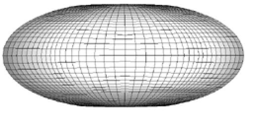
Since the mesh was to be refined locally, an additional consideration was the size of (or number of elements constituting) the localized refinement zone. Due to the near point contact characteristic of this model, it was determined that a 5x5 grid (25 elements) was sufficient to define each refined region. Figure 6 depicts the localized remeshing routine employed in two-dimensions. Our refinement strategy consists of first calculating a preliminary solution on the base mesh for a series of time steps. The local refinement procedure is invoked after an oscillatory resisting moment/force is observed. An error indicator is used to locate regions where greater mesh resolution is needed. A centralized element is located for each such zone. Finer grids are adaptively created in these error-prone regions and the solution and error indicators computed on the finer subgrids. An assessment of the program's ability to locate the region(s) to be refined was tested against a run with the base element(s) chosen manually by the analyst.
Figure 6.
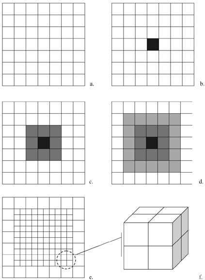
Adaptive meshing refinement strategy: (a) Coarse base mesh illustrated in two-dimensions; (b) the region to be refined is identified by first locating (b) the element experiencing the highest stress averaged over a period of three time steps; (c) the eight neighboring elements are identified, and (d) the elements immediately adjacent to this subset are also included, thereby totaling 25 base elements to be refined. Each element is then subdivided into 8 new elements, illustrated in (e) two- and (f) three-dimensions
The refinement scheme is recursive; thus, fine subgrids may be further refined by adaptively creating even finer subgrids. This relationship leads naturally to a tree data structure. Information regarding the geometry, solution, and error indicators of the base grid is stored as the root, or level 0, of the tree. Subgrids of the base grid are considered offspring and are stored as level 1 of the tree. The structure continues, with a grid at level i having a more coarse parent grid at level i-1 and additional finer offspring at level i+1. Our refinement procedure requires that no two grids overlap and that offspring grids must be properly nested within the boundaries of the parent grid (Figure 7). Additional finer grids are introduced in regions where the error indicators exceed the prescribed tolerance, and the model is solved again on the finer subgrids. Should the oscillatory contact exceed the bounds of the parent mesh, the original base mesh of the model is reinstated and a new parent mesh defined as initially described. This iterative process continues until the oscillatory behavior ceases or, for example, the implant successfully dislocates.
Figure 7. Recursive refinement patterns.

(a) To avoid overlapping the offspring grids with the original mesh, based on our current requirement of identifying a 5 x 5 grid, the central element of an offspring mesh must be located within the shaded region illustrated, thereby allowing the required elements to be subdivided appropriately (b). If however, the element falls outside of these bounds as illustrated in (c), the (d) original base mesh is restored and the process repeated.
EXAMPLE: VOLAR AND ROTATIONAL DISLOCATION OF THE UNIVERSAL TOTAL WRIST IMPLANT
Numerical studies were conducted to validate the effectiveness of the present technique. The adaptive computations were tested against two dislocation events: a volar and rotational dislocation. Each model was driven under displacement control through the respective dislocation event, first in the absence of the adaptive meshing routine. The adaptive meshing routine, choice of mesh discretization, and error estimator proved effective in reducing the solution's oscillatory behavior during both the rotational (Figure 8) and translational motions (Figure 9). Furthermore, the results supported the use of nested subgrids. Figure 10 illustrates the first two successive refinements during the rotational displacement (note that two separate zones were required during this event). The additional refinements showed a substantial decrease in the error (Figures 8, 9). The decision-making processes implemented in the algorithm proved successful, as compared to the manual selection, when identifying the region, or regions, to be refined (Figure 11).
Figure 8. Axial rotation vs. resistive moment.

The original rotational resistance is compared to that of the adaptively refined mesh with a single and a double level of refinement.
Figure 9. Translation vs. resistive moment.

The original rotational resistance is compared to that of the adaptively refined mesh with a single and a double level of refinement.
Figure 10.
Evolution of the mesh refinement through a rotational dislocation event, progressing from (a) the base mesh to (b) a parent mesh, and to (c) an offspring mesh
Figure 10a.
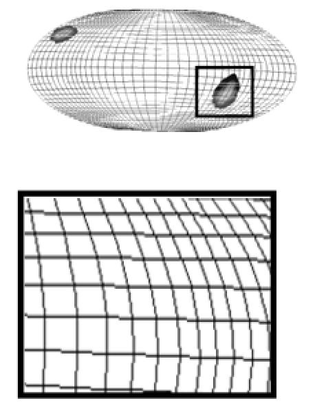
Figure 10b.

Figure 10c.

Figure 11.

A comparison of the manually (manual) chosen refinement zones versus those chosen automatically (Auto) by the algorithm compared favorably.
SUMMARY
An adaptive FE procedure has been developed, using an error estimator based on the oscillatory behavior of a near-point contact analysis. The techniques can be used effectively for enriching the solution space locally. The present approach for adaptive mesh refinement eliminates the use of transition zones and special transition elements. Numerical studies were performed to assess the effectiveness of the present approach for the local refinement of the global mesh in terms of the size of the refined zone(s), in addition to the ability to recursively refine the mesh without introducing significant mesh distortion. Although the present method is effective in avoiding local mesh distortion by eliminating transition zones, distortion of the global mesh is inevitable when discretizing a domain of arbitrary geometry. Consequently, the efficiency of our adaptive mesh-moving and refinement strategies are dependent on our ability to generate a suitable initial mesh and to regenerate a new base mesh should the need arise. The proper base mesh can reduce the need for refinement, and thus increase efficiency. Consequently, future endeavors may benefit from addressing the initial mesh definitions. Although our initial efforts have been applied to an FE model of a total wrist replacement, the methodology holds the potential to be applicable to the countless number of contact problems encountered in orthopaedic biomechanics.
References
- 1.Brase DW, Millender LH. Failure of silicone rubber wrist arthroplasty in rheumatoid arthritis. J Hand Surg. (Am) 1986;11:175–183. doi: 10.1016/s0363-5023(86)80047-8. [DOI] [PubMed] [Google Scholar]
- 2.Couteau B, Mansat P, Estivalèzes É, Darmana R, Mansat M, Egan J. Finite element analysis of the mechanical behavior of a scapula implanted with a glenoid prosthesis. Clinical Biomechanics. 2001;16(7):566–575. doi: 10.1016/s0268-0033(01)00029-8. [DOI] [PubMed] [Google Scholar]
- 3.Huiskes R, Chao EY. A survey of finite element analysis in orthopaedic biomechanics: the first decade. Journal of Biomechanics. 1983;16(6):385–409. doi: 10.1016/0021-9290(83)90072-6. [DOI] [PubMed] [Google Scholar]
- 4.Huiskes R, Verdonschot N, Nivbrant B. Migration, stem shape, and surface finish in cemented total hip arthroplasty. Clinical Orthopaedics & Related Research. 1998;355:103–112. doi: 10.1097/00003086-199810000-00011. [DOI] [PubMed] [Google Scholar]
- 5.Li L, Bettress P. Adaptive finite element methods: a review. Applied Mechanics Review. 1997;50(10):581–591. [Google Scholar]
- 6.Maxian TA, Brown TD, Pedersen DR, Callaghan JJ. The Frank Stinchfield Award. 3-Dimensional sliding/contact computational simulation of total hip wear. Clin Orthop. 1996;333:41–50. [PubMed] [Google Scholar]
- 7.Maxian TA, Brown TD, Pedersen DR, Callaghan JJ. A sliding-distance-coupled finite element formulation for polyethylene wear in total hip arthroplasty. Journal of Biomechanics. 1996;29(5):687–692. doi: 10.1016/0021-9290(95)00125-5. [DOI] [PubMed] [Google Scholar]
- 8.Miyoshi S, Takahashi T, Ohtani M, Yamamoto H, Kameyama K. Analysis of the shape of the tibial tray in total knee arthroplasty using a three dimension finite element model. Clinical Biomechanics. 2002;17(7):521–525. doi: 10.1016/s0268-0033(02)00064-5. [DOI] [PubMed] [Google Scholar]
- 9.Namba RS, Keyak JH, Kim AS, Vu LP, Skinner HB. Cementless implant composition and femoral stress. A finite element analysis. Clinical Orthopaedics & Related Research. 1998;347:261–267. [PubMed] [Google Scholar]
- 10.Pedersen DR, Brown TD, Maxian TA, Callaghan JJ. Temporal and spatial distributions of directional counterface motion at the acetabular bearing surface in total hip arthroplasty. Iowa Orthopaedic Journal. 1998;18:43–53. [PMC free article] [PubMed] [Google Scholar]
- 11.Prendergast PJ. Finite element models in tissue mechanics and orthopaedic implant design. Clinical Biomechanics. 1997;12(6):343–366. doi: 10.1016/s0268-0033(97)00018-1. [DOI] [PubMed] [Google Scholar]
- 12.Scifert CF, Brown TD, Lipman JD. Finite element analysis of a novel design approach to resisting total hip dislocation. Clinical Biomechanics. 1999;14(10):697–703. doi: 10.1016/s0268-0033(99)00054-6. [DOI] [PubMed] [Google Scholar]
- 13.Scifert CF, Brown TD, Pedersen DR, Callaghan JJ. A finite element analysis of factors influencing total hip dislocation. Clinical Orthopaedics & Related Research. 1998;355:152–162. doi: 10.1097/00003086-199810000-00016. [DOI] [PubMed] [Google Scholar]
- 14.Spilker RL, de Almeida ES, Donzelli PS. Finite element methods for the biomechanics of soft hydrated tissues: nonlinear analysis and adaptive control of meshes. Crit Rev Biomed Eng. 1992;20(3-4):279–313. [PubMed] [Google Scholar]
- 15.Vander Sloten J, Hobatho MC, Verdonck P. Applications of computer modelling for the design of orthopaedic, dental and cardiovascular biomaterials. Proc Inst Mech Eng [H] 1998;212(6):489–500. doi: 10.1243/0954411981534240. [DOI] [PubMed] [Google Scholar]
- 16.Walker PS, Nunamaker D, Huiskes R, Parchinski T, Greene D. A new approach to the fixation of a metacarpophalangeal joint prosthesis. Engineering in Medicine. 1983;12(3):135–140. doi: 10.1243/emed_jour_1983_012_035_02. [DOI] [PubMed] [Google Scholar]