Abstract
Previously validated hardware-only finite element models of THA dislocation have clarified how various component design and surgical placement variables contribute to resisting the propensity for implant dislocation. This body of work has now been enhanced with the incorporation of experimentally based capsule representation, and with anatomic bone structures. The current form of this finite element model provides for large deformation multi-body contact (including capsule wrap-around on bone and/or implant), large displacement interfacial sliding, and large deformation (hyperelastic) capsule representation. In addition, the modular nature of this model now allows for rapid incorporation of current or future total hip implant designs, accepts complex multi-axial physiologic motion inputs, and outputs case-specific component/bone/soft-tissue impingement events. This soft-tissue-augmented finite element model is being used to investigate the performance of various implant designs for a range of clinically-representative soft tissue integrities and surgical techniques. Preliminary results show that capsule enhancement makes a substantial difference in stability, compared to an otherwise identical hardware-only model. This model is intended to help put implant design and surgical technique decisions on a firmer scientific basis, in terms of reducing the likelihood of dislocation.
INTRODUCTION
Finite element analysis of total hip dislocation has opened new avenues for understanding the biomechanical factors underlying this all-too-common major complication of total hip arthroplasty (THA). Dislocation, which ranks second only to wear-induced aseptic loosening as a cause of failure, affects 2% to 11% of all patients in primary series and up to 25% of patients in revision series. One third of these dislocation patients require revision surgery due to recurrence, with only 60% of those revisions achieving satisfactory stability. The propensity for dislocation is influenced by many factors: mechanical design of the implant, inappropriate implant placement, untoward hip joint motions by the patient, bony impingement, and compromise of periarticular soft tissue integrity. Unfortunately, the relative influence of individual factors on dislocation propensity is difficult to determine from post hoc reviews of clinical records, due to the confounding effects of implant design, surgical technique, soft tissue compromise, surgeon experience, and other variables.
Recent finite element models of THA dislocation20–22 enable systematic study of how various total hip component design and surgical placement variables contribute to resisting the propensity for dislocation, during at-risk hip joint motions. That work has shown that improved stability (as measured by the peak moment developed to resist dislocation) comes at the expense of compromised range of motion, and conversely. To learn more about the mechanics of the dislocation process under clinically relevant circumstances, quantitative motion data from THA-age-matched (but non-implanted) human test subjects performing dislocation-prone maneuvers were subsequently implemented into this finite element formulation. Results of that study17, which highlighted seven clinically recognized posture/motion challenges, showed an overall computationally predicted dislocation incidence of 47% if these maneuvers in THA patients were to be followed through the full motion ranges exhibited by non-implanted subjects. The authors of that study emphasized, however, that other factors being equal, their finite element formulation tended to underestimate in vivo stability (thus overestimating dislocation propensity), owing to its use of a worst-case scenario in terms of head size and component surgical orientation, and owing to its absence of capsule representation. The availability of these unique human motion data make it feasible to systematically explore how the inclusion of capsule representation affects both dislocation kinetics and overall THA joint performance, compared to intrinsic "hardware-only" models.
The capsule is important to the stability and proper function of the hip joint. Clinical studies of hip stability primarily catalog the propensity for or treatment of dislocation following hip reconstruction 2,4,8,15,16,18,27, or less often following trauma6,9,14,19. Experimental studies of hip stability predominantly have explored the relationship of fracture fragment size and residual instability4,14,26,28,30, but also have addressed the passive restraints at the extremes of motion.29 Hewitt et al.12,13 have recently investigated the role of joint capsule in hip stability and movement by mechanically testing individual ligaments within the capsule itself. In a related study, this group33 has also shown that an intact posterior capsule increases (by ~2.5 times) the torque required to flex a prosthetic hip joint to dislocation. Since capsular insufficiency is well recognized clinically as predisposing to dislocation 34, incorporating capsule representation is an important next step for making THA finite element dislocation models more fully credible.
The current form of this FE model incorporates nonlinearities arising from finite-deformation multi-body contact, large displacement sliding at contact interfaces, and experimentally derived (hyperelastic) capsule representation. In addition, the modular nature of this model allows for easy incorporation of existing (or future) total hip component designs, at various positions and orientations of surgical placement. Under complex multi-axial physiologic motion inputs, the model reports case-specific component/bone/soft-tissue impingement events, as well as hardware subluxation and dislocation. The purpose of adding capsulo-ligamentous restraints to the THA dislocation finite element model is to improve the model's fidelity to the real world of patient function. This soft-tissue-augmented finite element model can potentially provide valuable new information on both the performance of implant designs for a range of clinically-representative soft tissue integrities, and information about stability differences for various surgical approaches and capsular repair techniques. Hopefully, this model can therefore help put implant design and surgical technique decisions on a firmer scientific basis in terms of reducing the likelihood of dislocation.
MATERIALS AND METHODS
For purposes of incorporating the entire hip capsule into the existing computational model (Figure 1), it was important to include the full circumferential mapping of material properties and geometry, and to unambiguously define a number of discrete sectors. This is because the forces transmitted by different portions of the capsule are entirely dependent upon the orientation of the femur relative to the acetabulum, and upon the location of any forces tending to distract the two bones (i.e., dislocate the hip). Eight individual capsule sectors were defined, as a compromise between needing to map a relatively large number of distinct circumferential locations, versus needing to have tissue samples be large enough to reliably test.
Figure 1.
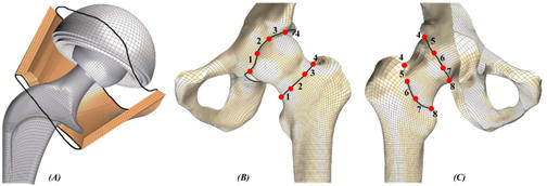
(A) Cut-away of the bony members, illustrating the finite element mesh of THA components and the capsule representation. The dark black lines illustrate the anatomic capsule attachment locus. (B) Anterior and (C) posterior views of the hemi-pelvis and femur finite element mesh, where the individual capsule sector definitions are identified by the red dots.
These eight capsule sectors were incorporated into the whole-joint finite element model at anatomically appropriate insertion points, using rigid body renditions of the femur and hemi-pelvis. As illustrated in Figure 2, detailed anatomic features of these bony structures were extracted from CT data, using edge-detection methods operating on 1-mm serial sections. Triangulated surfaces were fitted to the resulting point cloud data for the femur and hemi-pelvis. These surfaces, which were zoned with a three-dimensional, all-quadrilateral rigid body finite element mesh using TrueGrid's (v2.1, XYZ Scientific Applications, Inc., Livermore, CA) mesh generator, provide a quantitative spatial basis for establishing capsule attachment sites. Accurate registration of each capsule sector in this computational model was achieved using common reference points (the anatomical origin of the hip capsule near the anterior inferior iliac spine, and the insertion on the lesser trochanter) and initial geometric measurements obtained from previous experimental work25. Each capsule sector was meshed entirely with hexahedral continuum elements having experimentally-based material characteristics. Of the various hyperelastic material models examined, the Yeoh hyperelastic model 35 (a variation of the reduced-polynomial strain energy function) performed most satisfactorily, in terms of fitting the experimental stress-strain curves for the individual capsule sectors.
Figure 2.
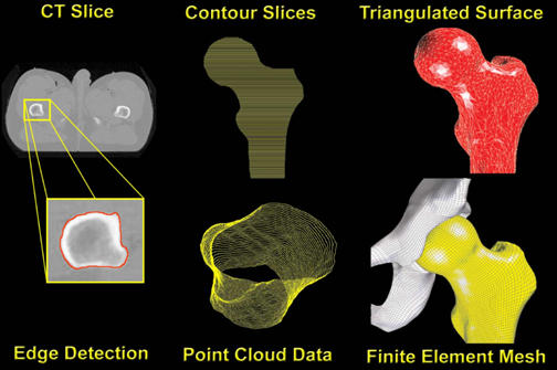
Full sequence of pre-processing steps, beginning with edge detection of individual CT slices. Point cloud data, which record the spatial coordinates of individual points along the detected periosteal surface, result from the accumulation of contoured slices taken at 1mm increments. A triangulated surface was then fitted to the point cloud data for each side of the joint (femur here illustrated). Finally, an all-quadrilateral finite element mesh was projected onto the triangulated surface. The same sequence is used for both the acetabular and femoral sides.
Like the earlier hardware-only dislocation models, THA components represented in this now bone/capsule/hardware finite element model consisted of three component parts: a titanium metal backing, an ultra-high molecular weight polyethylene (UHMWPE) acetabular component, and a CoCr alloy femoral component (including head and neck). The geometry adopted was that of a widely used metal-backed THA prosthesis*, with which our institution has considerable clinical and laboratory experience. The CoCr alloy of the femoral component and the titanium of the metal backing have on the order of a thousand-fold higher elastic moduli than UHMWPE. These metal components were therefore modeled and meshed as rigid bodies, composed of three-dimensional, all-quadrilateral rigid body elements. The acetabular liner was modeled as geometrically and materially nonlinear, with constitutive behaviour based on the fourth order polynomial relationship between von Mises stress and tangent modulus reported by Cripton7, and implemented in ABAQUS by Scifert et al.20,22.
The inclusion of hip capsule representation (in the form of eight discrete sectors) introduced the option for multiple independent contact interfaces. Due to recent contact algorithm improvements, ABAQUS/Explicit V6.3-1 (ABAQUS, INC., Pawtucket, RI) provides an efficient method for solving complex contact problems that include such multiple surface definitions. Within ABAQUS/Explicit, general contact simulations are defined by three distinct steps: (1) specifying the surfaces of the bodies that could potentially come into contact, (2) specifying which pairs of such surfaces potentially interact with one another, and (3) specifying the mechanical surface interaction phenomena that govern the behavior of such surface pairs when they are in contact. ABAQUS/Explicit contact capabilities include finite-sliding contact between deformable bodies (e.g., capsule against UHMWPE), contact between a rigid surface and a deformable body (e.g., femoral component against UHMWPE, metal backing against UHMWPE), contact between rigid surfaces (femoral component impinging against metal backing), and contact between a single deformable body and itself (i.e., infolding of individual capsule sectors). In the finite element model, the THA implant components are surrounded by eight distinct deformable capsule regions, each having individual hyperelastic material characteristics. Each such capsule sector can potentially come in contact with the metal backing, the UHMWPE, the femoral component, other capsule sectors, and/or itself, during a dislocation motion event. For all of these possible contact scenarios that could involve capsule wrap-around, ABAQUS/Explicit therefore provides the necessary contact simulation capabilities.
The ability to pre-position the THA components in numerous surgical orientations using tilt and anteversion rotations (Figure 3) provides much-needed flexibility for exploring the effects of surgically-achieved component orientation as a factor pre-disposing to dislocation. A cup placement position of 40 degrees of tilt and 10 degrees of anteversion was chosen, centrally oriented within the conventional "safe zone" for cup placement (30-50 degrees of tilt and 5-25 degrees of anteversion). A global coordinate system origin was defined at the center of the cup, using the following reference frame: X-direction being anterior, Y-direction being medial, and Z-direction being superior. Rotation of the acetabular component about the horizontal plane was performed so as to place it into a surgical orientation of 40 degrees of tilt (abduction). Then, the "tilted" component was rotated about the superior axis, to 10 degrees of anterversion. By definition, each rigid body is associated with a specific node, termed the rigid body reference node, whose motion governs the motion of the entire rigid body. The global origin was used to define two such rigid body reference nodes: one for the metal backing and one for the femoral component. Application of a zero displacement boundary condition (in all three coordinate directions) at the metal backing reference node kept the metal liner constrained against motion throughout the simulation. To highlight the capsule's contribution to stability, kinematics and kinetics were input for the most dislocation-prone maneuver identified by Nadzadi et al.17: the low sit-to-stand maneuver, as occurs when rising from a toilet. As implemented in previous models, joint loads and boundary conditions for this specific challenge maneuver were prescribed at the femoral component rigid body reference node. For preliminary validation purposes, the FE model (run using the ABAQUS/Standard v6.3-1 code) had previously been utilized to replicate the simpler situation of an intact, whole-capsule cadaveric hip tensile test 24, in which the femur (with natural femoral head) was distracted away from the acetabulum, in the direction of the femoral neck axis. The previous load-displacement and stress calculations for that simpler test were confirmed using the ABAQUS/Explicit V6.3-1 finite element code.
Figure 3.
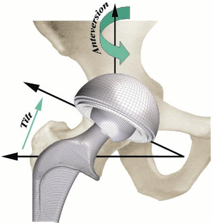
Finite element model surgical placement parameters: cup tilt is defined by the abduction angle from horizontal. Then rotating the 'tilted' component about the superior axis specifies cup anteversion.
RESULTS
Modeling the metal backing and femoral component as rigid bodies (each controlled by an independent rigid body reference node) allowed for straightforward tracking of resultant resisting moments (Figure 4). In addition, femoral flexion was explicitly tracked. Resisting moment development as a function of angular motion input (femoral flexion angle) served as the key output metric for this study. Typical resisting moment profiles for "hardware-only" models consisted of three distinct phases: (1) an initial non-zero baseline moment (typically less than 0.2 Nm) due to bearing friction between the UHMWPE liner and the femoral head (friction coefficient = 0.038); (2) the onset (toe region of the resisting moment profile) and eventual full engagement of impingement contact (linearly increasing portion of the resisting moment profile); and (3) a subluxation phase which initiates near the peak resisting moment and is signalled by downslope of the femoral resisting moment value, until onset of computational instability (corresponding to physical dislocation). In the capsule-enhanced model, by contrast, the angular motion input was met with substantial resistance due to progressive tautening of the capsule even from the initiation of flexion. This tautening resistance resulted in a dramatic increase in the resisting moment developed throughout the low sit-to-stand maneuver (see Figure 4). Once impingement occurred, there was an additional, more precipitous spike of resisting moment, roughly comparable to that seen for impingement onset in the hardware-only model. For this particular extreme maneuver, the capsule was stressed (to about 70% of its failure strength25). Since this taughtened tissue lies appreciably eccentric to the neck-liner impingement fulcrum, it works efficiently "in parallel" with the implant itself to resist the tendency for dislocation (Figure 5), reducing the peak polyethylene stresses at the impingement site and at the head egress site by typically 27% and 50%, respectively, relative to the hardware-only case. These preliminary results show that capsule representation provides approximately a 3.6-fold increase in construct stability, compared to an otherwise identical hardware-only construct.
Figure 4.
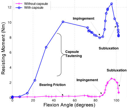
Femoral resisting moment comparison between hardware-only and capsule-enhanced models.
Figure 5.
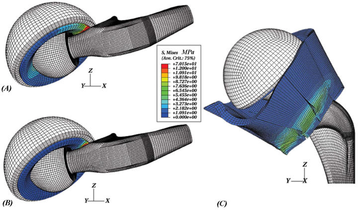
(A) Component-only model at an instant well into impingement, (B) component mesh of the capsule-augmented model at the same configuration, and (C) posterior view of stress contours within the capsule sectors during a low sit-to-stand maneuver.
DISCUSSION
The purpose of adding capsulo-ligamentous restraints to the THA dislocation model was to improve the model's applicability to the full reality of patient function. Maximal dislocation resistance of the hardware construct itself is of course absolutely desirable. However, the inclusion of the nonlinear restraints (especially, capsulo-ligamentous tautening) was felt to be likely to substantially alter dislocation kinetics. This may lead, for example, to substantially less net clinical efficacy of a specific implant design improvement than might be apparent strictly from the intrinsic hardware performance. Experience to date with hardware-only dislocation models has been that changes of individual component design parameters (e.g., liner lip bevel angle, neck taper angle, head center insert, etc.) which achieve improved stability (as measured by the peak moment developed to resist dislocation) come at the expense of compromised range of motion, or conversely. While implants can be designed to strongly favor either stability or range of motion, hardware-only finite element models provide no guidance as to which type of design is better suited to an individual patient's need, especially if capsule compromise is appreciable.
Successful application of the finite element method to studies of joint and capsule/ligament mechanics is a significant technical challenge, due to complex geometries, large deformations, multi-body contact, and the in situ stress that provides resting capsule tension and joint stability. In addition, realistically modeling capsule/ligament structures requires a detailed mathematical description of the material behavior. Previous finite element joint models that have incorporated ligament mechanics into their formulation have used one-dimensional ligament representations1,3,5,11 (simple springs), two-dimensional representations23 (isotropic plane strain quadrilateral membrane elements), and fully three-dimensional (hexahedral continuum elements) representations10,31,32. Using one-dimensional spring elements, the capsule material behavior can be characterized using a simple (often times nonlinear) load-elongation relationship, which greatly reduces the overall complexity of the model. Unfortunately, one-dimensional representations lack the ability to predict capsule stress distributions, and only allow joint load transfer at the discrete element attachment points (i.e., wrap-around contact between the capsule and the bone/implant is not accommodated). Two-dimensional representations are also insufficient for determining stress distributions throughout the capsule material. Since the forces transmitted by a different portion of the capsule are heavily dependent upon the orientation of the femur relative to the acetabulum, and upon the location of any forces tending to distract the two bones (i.e., dislocate the hip), it was important to make the investment of treating the capsule as a full three-dimensional continuum, with experimentally-based hyperelastic material properties.
Now that capsule inclusion in the total hip dislocation model has been achieved, an attractive application will be to undertake parametric trials of how stability-favoring versus range-of-motion-favoring implant designs perform - in terms of avoiding dislocation - under a range of clinically representative soft tissue integrities. Specific parameters of interest for such purpose include generalized capsulo-ligamentous laxity, and localized stiffness deficit (or absence) of individual ligament and/or capsule structures. These soft tissue abnormalities can be reasonably well appreciated on careful clinical examination, but there currently is no objective basis for knowing what (if anything) to do differently from case to case in terms of implant choice or targeted surgical positioning of the components. Another attractive application will be to undertake parametric series to help put surgical technique decisions on a firmer mechanical basis. Currently, several very distinct surgical approaches to the hip joint are advocated. Surgical approach is widely recognized as a factor in the different dislocation rates experienced by individual surgeons, but the arguments advanced in favor of one or another approach remain entirely subjective. (The particular approach in use at the institution where the surgeon happened to have trained, for example, is often favored simply from familiarity). A related issue is the extent of capsular excision that is appropriate during surgery. Tradeoffs for the presumed stability decrease that accompany partial or full capsule excision include improved surgical exposure and improved range of motion. The gamut of considerations (again, subjectively based) includes complete capsule removal, posterior capsule removal, distal capsule preservation, superior capsule preservation, or complete capsule preservation. And, the effects of complete or partial incision repair could be quantified for any of these surgical approach variants. Clearly, the capsule-enhanced finite element model can introduce a much-needed source of information for objectively studying these issues, especially during the present era where novel surgical approaches are rapidly evolving for minimally invasive procedures.
ACKNOWLEDGMENTS
This study was supported in part by NIH AR46601. We wish to acknowledge the technical contributions of Dr. Anthony Petrella of DePuy, Inc and of Dr. Nicole Grosland.
Footnotes
Endurance Stem (Size 3, Standard Offset) and Duraloc Metal Shell (2/Cluster Hole 54mm OD), Depuy Inc., Warsaw, IN.
References
- 1.Abdel-Rahman E, Hefzy MS. A two-dimensional dynamic anatomical model of the human knee joint. J Biomech Eng. 1993;115(4A):357–365. doi: 10.1115/1.2895498. [DOI] [PubMed] [Google Scholar]
- 2.Amstutz HC, Lodwig RM, Schurman DJ, Hodgson AG. Range of motion studies for total hip replacements. A comparative study with a new experimental apparatus. Clin Orthop. 1975;111:124–130. doi: 10.1097/00003086-197509000-00016. [DOI] [PubMed] [Google Scholar]
- 3.Andriacchi TP, Mikosz RP, Hampton SJ, Galante JO. Model studies of the stiffness characteristics of the human knee joint. J Biomech. 1983;16(1):23–29. doi: 10.1016/0021-9290(83)90043-x. [DOI] [PubMed] [Google Scholar]
- 4.Bartz RL, Nobel PC, Kadakia NR, Tullos HS. The effect of femoral component head size on posterior dislocation of the artificial hip joint. J Bone Joint Surg. (Am) 2000;82(9):1300–1307. doi: 10.2106/00004623-200009000-00010. [DOI] [PubMed] [Google Scholar]
- 5.Blankevoort L, Kuiper JH, Huiskes R, Grootenboer HJ. Articular contact in a three-dimensional model of the knee. J Biomech. 1991;24(11):1019–1031. doi: 10.1016/0021-9290(91)90019-j. [DOI] [PubMed] [Google Scholar]
- 6.Calkins MS, Zych G, Latta L, Borja FJ, Mnaymneh W. Computed tomography evaluation of stability in posterior fracture dislocation of the hip. Clin Orthop. 1988;227:152–163. [PubMed] [Google Scholar]
- 7.Cripton P. Mechanical Engineering. Kingston: Queen's University at Kingston; 1993. Compressive characterization of ultra-high molecular weight polyethylene with applications to contact stress analysis of total knee replacements. Edited. [Google Scholar]
- 8.Dorr LD, Wolf AW, Chandler R, Conaty JP. Classification and treatment of dislocations of total hip arthroplasty. Clin Orthop. 1983;173:151–158. [PubMed] [Google Scholar]
- 9.Epstein HC. Posterior fracture-dislocations of the hip; long-term follow-up. J Bone Joint Surg. (Am) 1974;56(6):1103–1127. [PubMed] [Google Scholar]
- 10.Gardiner JC, Weiss JA. Subject-specific finite element analysis of the human medial collateral ligament during valgus knee loading. J Orthop Res. 2003;21(6):1098–1106. doi: 10.1016/S0736-0266(03)00113-X. [DOI] [PubMed] [Google Scholar]
- 11.Hefzy MS, Grood ES. An analytical technique for modeling knee joint stiffness--Part II: Ligamentous geometric nonlinearities. J Biomech Eng. 1983;105(2):145–153. doi: 10.1115/1.3138398. [DOI] [PubMed] [Google Scholar]
- 12.Hewitt J, Guilak F, Glisson R, Vail TP. Regional material properties of the human hip joint capsule ligaments. J Orthop Res. 2001;19(3):359–364. doi: 10.1016/S0736-0266(00)00035-8. [DOI] [PubMed] [Google Scholar]
- 13.Hewitt JD, Glisson RR, Guilak F, Vail TP. The mechanical properties of the human hip capsule ligaments. J Arthroplasty. 2002;17(1):82–89. doi: 10.1054/arth.2002.27674. [DOI] [PubMed] [Google Scholar]
- 14.Keith JE, Brashear HR, Guilford WB. Stability of posterior fracture-dislocations of the hip. Quantitative assessment using computed tomography. J Bone Joint Surg. (Am) 1988;70(5):711–714. [PubMed] [Google Scholar]
- 15.McCollum DE, Gray WJ. Dislocation after total hip arthroplasty. Causes and prevention. Clin Orthop. 1990;261:159–170. [PubMed] [Google Scholar]
- 16.Morrey BF. Instability after total hip arthroplasty. Orthop Clin North Am. 1992;23(2):237–248. [PubMed] [Google Scholar]
- 17.Nadzadi ME, Pedersen DR, Yack HJ, Callaghan JJ, Brown TD. Kinematics, kinetics, and finite element analysis of commonplace maneuvers at risk for total hip dislocation. J Biomech. 2003;36(4):577–591. doi: 10.1016/s0021-9290(02)00232-4. [DOI] [PubMed] [Google Scholar]
- 18.Nicholas RM, Orr JF, Mollan RA, Calderwood JW, Nixon JR, Watson P. Dislocation of total hip replacements. A comparative study of standard, long posterior wall and augmented acetabular components. J Bone Joint Surg. (Br) 1990;72(3):418–422. doi: 10.1302/0301-620X.72B3.2341440. [DOI] [PubMed] [Google Scholar]
- 19.Pantazopoulos T, Nicolopoulos CS, Babis GC, Theodoropoulos T. Surgical treatment of acetabular posterior wall fractures. Injury. 1993;24(5):319–323. doi: 10.1016/0020-1383(93)90055-b. [DOI] [PubMed] [Google Scholar]
- 20.Scifert CF, Brown TD, Lipman JD. Finite element analysis of a novel design approach to resisting total hip dislocation. Clin Biomech (Bristol, Avon) 1999;14(10):697–703. doi: 10.1016/s0268-0033(99)00054-6. [DOI] [PubMed] [Google Scholar]
- 21.Scifert CF, Brown TD, Pedersen DR, Callaghan JJ. A finite element analysis of factors influencing total hip dislocation. Clin Orthop. 1998;355:152–162. doi: 10.1097/00003086-199810000-00016. [DOI] [PubMed] [Google Scholar]
- 22.Scifert CF, Brown TD, Pedersen DR, Heiner AD, Callaghan JJ. Development and physical validation of a finite element model of total hip dislocation. Computer Methods in Biomechanics and Biomedical Engineering. 1999;2:139–147. doi: 10.1080/10255849908907983. [DOI] [PubMed] [Google Scholar]
- 23.Simbeya KW, Shrive N, Frank CB, Matyas JR. A micromechanical finite element model of rabbit medial collateral ligament. Recent Advances in Computer Methods in Biomechanics and Biomedical Engineering. 1992. pp. 240–249.
- 24.Stewart K, Pedersen D, Brand R, Brown T. Proceedings of the Orthopaedic Research Society. New Orleans, LA: 2003. Hyperelastic representation of hip joint capsule: a finite element validation. [Google Scholar]
- 25.Stewart KJ, Edmonds-Wilson RH, Brand RA, Brown TD. Spatial distribution of hip capsule structural and material properties. J Biomech. 2002;35(11):1491–1498. doi: 10.1016/s0021-9290(02)00091-x. [DOI] [PubMed] [Google Scholar]
- 26.Thomas KA, Vrahas MS, Noble JW, Bearden CM, Reid JS. Evaluation of hip stability after simulated transverse acetabular fractures. Clin Orthop. 1997;340:244–256. doi: 10.1097/00003086-199707000-00032. [DOI] [PubMed] [Google Scholar]
- 27.Turner RS. Postoperative total hip prosthetic femoral head dislocations. Incidence, etiologic factors, and management. Clin Orthop. 1994;301:196–204. [PubMed] [Google Scholar]
- 28.Vailas JC, Hurwitz S, Wiesel SW. Posterior acetabular fracture-dislocations: fragment size, joint capsule, and stability. J Trauma. 1989;29(11):1494–1496. [PubMed] [Google Scholar]
- 29.Vrahas MS, Brand RA, Brown TD, Andrews JG. Contribution of passive tissues to the intersegmental moments at the hip. J Biomech. 1990;23(4):357–362. doi: 10.1016/0021-9290(90)90065-b. [DOI] [PubMed] [Google Scholar]
- 30.Vrahas MS, Widding KK, Thomas KA. The effects of simulated transverse, anterior column, and posterior column fractures of the acetabulum on the stability of the hip joint. J Bone Joint Surg. (Am) 1999;81(7):966–974. doi: 10.2106/00004623-199907000-00009. [DOI] [PubMed] [Google Scholar]
- 31.Weiss JA, Gardiner JC. Computational modeling of ligament mechanics. Crit Rev Biomed Eng. 2001;29(3):303–371. doi: 10.1615/critrevbiomedeng.v29.i3.20. [DOI] [PubMed] [Google Scholar]
- 32.Weiss JA, Gardiner JC, Bonifasi-Lista C. Ligament material behavior is nonlinear, viscoelastic and rate-independent under shear loading. J Biomech. 2002;35(7):943–950. doi: 10.1016/s0021-9290(02)00041-6. [DOI] [PubMed] [Google Scholar]
- 33.Wellman S, Hewitt J, Glisson R, Guilak F, Vail TP. Proceedings of the Orthopaedic Research Society. Dallas, TX: 2001. An intact posterior hip capsule increases resistance to dislocation in a cadaveric model of total hip arthroplasty; p. 0989. [Google Scholar]
- 34.Woo RY, Morrey BF. Dislocations after total hip arthroplasty. J Bone Joint Surg. (Am) 1982;64(9):1295–1306. [PubMed] [Google Scholar]
- 35.Yeoh OH. Characterization of elastic properties of carbon-black-filled rubber vulcanizates. Rubber Chemistry and Technology. 1990;63(5):792–805. [Google Scholar]


