Abstract
The purpose of this study was to develop an imageless (without preoperative computerized tomography (CT) scans or intraoperative fluoroscopy) computer navigation system for total hip replacement. One-hundred and ninety-five hips were operated with imageless computer navigation. Eighty-five hips were operated prior to obtaining precise results, with precision refined in the subsequent 110 hips. Computer accuracy for cup-adjusted anteversion was achieved in 100% of the final 40 hips, and for adjusted inclination in 96.6%. The factors necessary for accurate measurements are mechanical stability of the tools with the light-emitting diodes, adjusted computer anteversion and inclination for the tilt of the pelvis (tilt in the AP plane), and check-and-balance techniques for confirmation of measurements of tilt, anteversion and inclination.
INTRODUCTION
In 1998, DiGioia et al.2 won the Aufranc Award of the Hip Society for his pioneering work using computer navigation for cup placement. He used preoperative computed tomography scans to define the desired position of 40 degrees abduction and 20 degrees anteversion for an individual patient, and then use this information intraoperatively to achieve this goal. After DiGioia presented his findings, there was an enthusiasm born for computer navigation methods. DiGioia continued to report his results, which showed precision of cup placement with his image-driven navigation even with small incisions. Jolles et al.4 had the same precision with plastic pelvis models which had image-driven navigation and the average error of 1.5 degrees anteversion and 2.5 degrees abduction. Nogler et al.9 used an imageless system in cadavers and found more consistent placement of the cup than with mechanical guides.
The necessity for a preoperative CT scan, or even intraoperative fluoroscopy, has been a deterrent to the use of navigation for many surgeons. This technique seems cumbersome and impractical to most surgeons in their busy practice. For this reason, interest in an imageless navigation system for total hip replacement became prevalent among those interested in navigation. This study was initiated with the hypothesis that an imageless computer navigation system could be developed which would be more accurate than manual methods and would be easy and efficient to use with little risk of complication. This system would then be practical for the practicing orthopedic surgeon and would provide the surgeon with "real time" knowledge of the component position. This knowledge would reduce the risk of impingement of the total hip replacement which was being performed.
MATERIALS AND METHODS
In February 2003, with approval of the Institutional Review Board and with informed consent of the patients, a clinical investigation was begun of an imageless computer navigation system. This imageless computer-assisted navigation was approved by the Federal Drug Administration (FDA) in November of 2003. The anticipated complaints were mostly associated with the use of percutaneous pins for placement of the base supports for the antennae which held the light emitting diodes. The operation was performed identical to a surgery without computer assisted navigation. The intraoperative registration of the acetabulum was non-invasive. Component placement could be performed by the surgeon, as needed, if there was mechanical or computer malfunction.
All operations were performed by a single surgeon (LDD). None were performed by residents or fellows. The operations were performed with a posterior mini-incision measuring 8-10 cm as previously described1. Implants used were the anatomic porous replacement stem (APR, Zimmer, Warsaw, IN), the Converge cup (Zimmer, Warsaw, IN) with either a Metasul (Zimmer, Warsaw, IN) or Durasul liner (Zimmer, Warsaw, IN). In these patients, the largest femoral head which could be used was used. The only head sizes available for Metasul was 28 mm, so its use was limited to 49-51 mm sockets. For Durasul, 32 mm heads were used for 51-55 mm sockets, 38 mm for 57-61 sockets, and above 61 mm a 44 mm head was used. No extended liners were used.
Technical Aspects of Imageless Computer Navigation
The tools to be used during surgery for registration of anatomy and components must be calibrated prior to use. The calibration allows the computer software to identify the tools during use. Calibration is accomplished by the scrub technician and the circulating nurse while the patient is being prepared for anesthesia, and requires approximately 5 minutes.
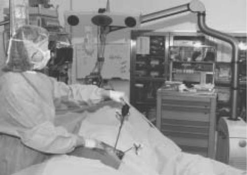
Navigation data is recorded using a Polaris Optical Localization System (Polaris, Northern Digital Instruments) using light emitting diodes (LED) (Figure 1). Surgical instruments and patient references are equipped with reflective spheres allowing tracking of their location during the surgery. The navigation software is image-free. The coordinate system and other reference points of the patient are digitized using a dedicated instrument, the registration pointer. All landmarks are digitized in relation to a patient reference that is rigidly fixed to the relevant bone of the patient.
Figure 1.
The AP plane of the pelvis is being registered with the pointer guide on the anterior iliac spine. The pelvic base with the light-emitting diodes on the tracker and the pointer are seen by the optical camera at the head of the table which is attached to the hardware for the navigation system. The computer screen is on a separate piece of equipment.
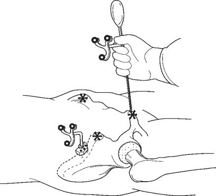
The registration of the anteroposterior (AP) plane of the pelvis (anatomic coordinate system) is done after the patient is anesthetized (Figure 2). This can be done while the anesthesiologist is completing the preparation, such as inserting arterial lines. The skin over the pelvis is sterilized with Betadine (Purdue Pharma L.P., Stamford, CT). A metal base plate is attached to the iliac crest with three percutaneous threaded 1/8-inch pins (Zimmer, Warsaw, IN). This metal base holds the pelvis antenna with the light emitting diodes (LED) for registration of pelvic information. The pelvic reference used for navigation is a unique modular design allowing removal of the antenna from its base and placing it back later in the exact same location. The registration pointer guide is touched to each anterior superior iliac spine (ASIS) and the pubis. The pointer touching the ASIS does not need to puncture through skin to the bone, but this should be done if there is fat over the ASIS obscuring the prominent bone. The pointer should always puncture through skin to the pubic bone because of the thickness of fat over the pubis. The cephalad border of the symphysis pubis is palpated and the pointer is directed to the pubic bone just below this border so that it contacts the pubic bone near the left or right pubic tubercle. The pubic tubercle is not palpable in many patients because of the thickness of fat. This process of registration of the AP plane requires no more than ten minutes to accomplish.
Figure 2.
The AP plane of the pelvis is registered with the patient in the supine position by touching the digitizing probe to the bone of the two ASIS and pubis.
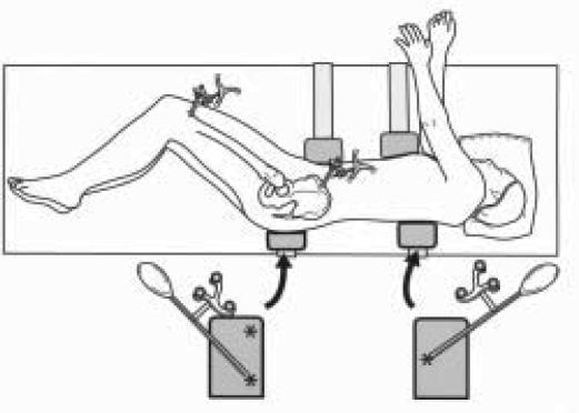
The patient is turned to the lateral decubitus position and secured with pelvis and chest supports to minimize pelvis motion during the operation. The long axis of the body in the lateral position is registered by touching the pointer to the posterior pelvic and chest supports (Figure 3). The computer software mathematically computes the tilt of the pelvis (tilt of AP plane) in the lateral position. This process takes one minute of time.
Figure 3.
The patient is in the lateral position for the operation and supported by two pelvic and two chest supports. The two posterior supports are those touched by the registration pointer to register the longitudinal axis of the body. The registration of the long axis of the body is done by creating a triangle on the two posts. This figure illustrates the triangle with two points on the pelvic post. A second tilt measurement is done with the triangle reversed with two points on the chest post. The pelvic and femoral antennae with light-emitting diodes are shown.
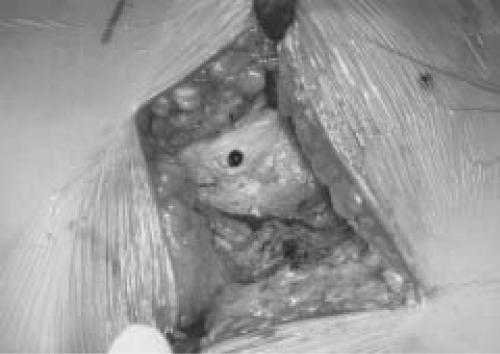
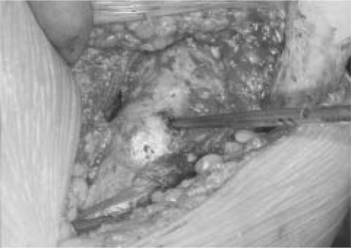
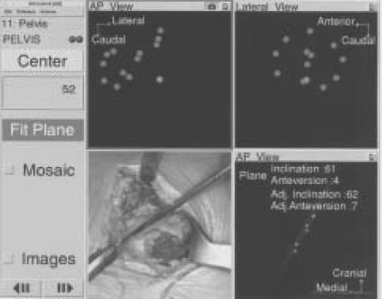
If just the acetabulum is to be navigated (no femoral navigation), the leg length and offset of the hip can still be determined. After incision to the level of the greater trochanter and prior to dislocation, the greater trochanter is touched with the pointer to register the preoperative position. A divot in the trochanter bone is made so the initial site can be located after the reconstruction. When the replacement is completed and the hip relocated, the change in offset and leg length are recorded by touching the same site on the greater trochanter (Figure 4). The software can then compare the preoperative and post-implantation positions. There are three registrations of the acetabulum done intraoperatively (Figure 5). After exposure of the acetabulum, and removal of the pulvinar to expose the cortical bone of the cotyloid notch that represents the medial wall, the pointer is used to touch the acetabular bone. The first registration locates the center of rotation (CR) of the hip and is performed with 16 touches of the inner wall, avoiding the cotyloid notch. The second registration is named 'the Mosaic.' By touching the periphery of the bone, the medial wall and cotyloid notch, the outline of the acetabular anatomy is obtained. The third set of points is named the 'fit plane' and the data is obtained by six points on the periphery of the acetabulum that defines the inclination and anteversion of the natural bone. Osteophytes and the cotyloid notch need to be avoided with this registration.
Figure 4a.
The point of registration on the greater trochanter is marked with methylene blue so that it can be easily found at the completion of the hip replacement.
Figure 4b.
The change in leg length and offset are measured by touching the same point on the greater trochanter with the registration pointer.
Figure 5.
The acetabular bone is touched by the pointer guide as seen in the lower left-hand quadrant. The computer screen shows the outline of the AP and ML dimensions of the acetabulum with the medial bone marked by yellow dots. The lighter central dot measures the center of rotation of the hip. This is seen in the upper two quadrants. The lower right quadrant shows the inclination and anteversion of the native acetabulum as determined by the fit plane.
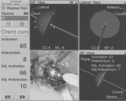
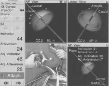
Three-dimensional change of the center of rotation during acetabular preparation and implantation is given by numerical changes in the superior-inferior, mediolateral and anterior-posterior planes during reaming (Figure 6). The medialization of the center of rotation can be anticipated from preoperative planning. When the cup is implanted, the inclination and anteversion, adjusted for the tilt of the AP pelvis, are visualized on the computer screen and the surgeon can adjust the cup position to the numerical position required (Figure 7).
Figure 6.
The reamer in the acetabulum is shown in the lower left-hand quadrant. The position of the reamer relative to the acetabular peripheral bone and medial wall is shown in the upper two quadrants. The CC is center of rotation (positive number means superior displacement); ML is mediolateral displacement from the center of rotation by the reaming (negative number means medial displacement); AP is the anterior-posterior position of the reamer (negative number means posterior displacement). The numbers on the left give the angular position of the reamer in the acetabulum both by inclination and anteversion, which is also adjusted.
Figure 7.
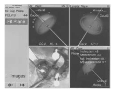
The cup implantation is shown in the lower left quadrant. The upper quadrant shows the position of the cup relative to the acetabular bone including medial wall. The CC, ML and AP numbers provide the center of rotation superior displacement (CC), medialization (ML) and AP displacement (AP). The numbers on the left give the numerical inclination and anteversion, and AdjAV and AdjI. The lower right quadrant gives the native acetabulum values, and the gray lines show what portion of the cup would be uncovered. The amount of coverage is only illustrative.
The cup position is known because of the LED on the cup holder. If the antenna attachment becomes loose, the values can be wrong. For this reason, we always confirm the reading from the cup holder by performing a fit-plane measurement of the metal edge of the cup after the cup holder is removed (Figure 8). Six points are touched on the circumference of the metal edge to confirm the inclination and anteversion of the cup. Furthermore, if a screw is used, it is possible to change the final position. A fit plane should be done to record any change in position that occurred. The fit plane is also done after the liner is impacted into place to determine any change that occurs with that impaction.
Figure 8.
The measurement of the fit plane of the acetabular cup is done by touching the metal edge of the cup at six points with the registration pointer.
Data Collection
One-hundred and ninety-five total hip replacements were performed with computer navigation between February 2003 and October 2004. Eighty-five hips were operated on in 79 patients in 2003 (group 1), and 110 hips in 100 patients in 2004 (which were divided into 70 patients operated on between January and July 2004, group 2; and 40 patients operated on between July and October 2004, group 3). The demographics of the patients in these groups were not different.
The first 85 hips from 2003 (group 1) included 53 men and 38 women. The 110 hips (groups 2 and 3) in 2004 included 54 men and 56 women. The age averaged 63 ± 11 years (37-89) versus 63 ± 13 years (32-90); the body mass index (BMI) was 28 ± 5 (20-44) versus 26 ± 5 (17-45). The diagnosis in 85 hips (group 1) versus 110 hips (group 2 and 3) was osteoarthritis in 76 versus 91, post-trauma in three versus one, osteonecrosis in three versus 11, and congenital disease of the hip in three versus seven.
Accuracy of a measurement is comparison of the measured value to the true value (i.e., the computer anteversion vs. the true anteversion of the cup). Precision is the agreement between two measured values to demonstrate reproducibility of a test. If the values tested are the same as the true value, then both values are also accurate. To determine the accuracy of the radiographic technique, and the computer navigation technique, postoperative CT scans were obtained which were considered the true value of cup anteversion.
The radiographic technique used for measurement of anteversion was published in 1996.12 It requires an AP pelvis radiograph centered over the symphysis pubis, and an AP hip radiograph centered over the hip. Centering the AP hip radiograph was difficult with the immediate postoperative radiograph, so it was only used to confirm anteversion versus retroversion. Data from comparison of 100 radiographs showed an average difference of 3.6 ± 2.0 degrees, so that the radiographic anteversion used for comparison to the computer anteversion was that of the AP pelvis radiograph plus four degrees.
Postoperative CT scans were obtained from 15 patients in group 2 to validate the radiographic and computer numbers. The CT scan images were segmented using Navitrack CT-based hip software (Orthosoft, Montreal, Canada) to reconstruct the 3-D model of the pelvic bone with the implanted cup. The planning module of the Navitrack CT-based hip software is used to evaluate the implanted cup orientation based on the coordinate system used during the surgery. The coordinate system is defined by aligning the frontal plane to both the ASIS and the pubic tubercles, and the lateral axis through the ASIS. Generic cup models can then be superimposed to the postoperative reconstruction of the implanted cup. The resulting inclination and anteversion angles can then be compared to the navigation data.
Precision of the measurements were given a margin of error of five degrees so that the radiographic and computer values had to be ± 5 degrees of each other or the computer number was considered an outlier. Five degrees was the margin of error because: 1) The difference between AP pelvis and AP hip radiographs was four degrees; 2) The range of difference between postoperative CT scans of cup position and postoperative radiographs in 15 patients was 0-5 degrees (average 1.8 degrees); 3) The average range between the 15 postoperative CT scans and computer navigation cup position was 0-6 degrees (mean 2.7 degrees); and 4) The standard deviation in postoperative radiographs for inclination and anteversion by this same radiographic technique for 105 hips performed without navigation was 38.4 ± 6.3 degrees for inclination and 20.1 ± 5.7 degrees for anteversion. The authors felt the computer must have better accuracy than their data from manual implantation of the identical cup.1
Development of Precision of Anteversion and Inclination
Four lessons were learned during the nearly one-year time period during which the first 85 hips were operated. The first 17 hips in this group had 13 (76%) outliers. In these hips, the pins holding the base for the pelvic antenna would loosen with anterior retraction of the femur and/or impaction of the cup. The base was moved to the thickest bone of the iliac crest, about 5 cm posterior to the ASIS, and secured to the bone with horizontal 1/8-inch threaded pins. The pin site was located by marking it with methylene blue through the pin holes on the base plate, a stab wound with a #15 scalpel blade was done, and the pins inserted.
The second lesson was that the tilt of the pelvis must be calculated into the anteversion and this was measured in the next 40 hips (hips number 18-57) with the patient supine on the operating table. Tilt of the pelvis (which reflects tilt of the AP plane) means flexion (anterior tilt) or extension (posterior tilt) to the longitudinal axis of the body (Figures 9A and 9B). The actual anteversion decreases with flexion (anterior tilt) and increases for extension (posterior tilt). The effect on anteversion is not 1:1 for the degree of tilt, so the computer software calculates a true anteversion and this is expressed as the adjusted anteversion (AdjAV). After measurement of tilt in the supine position, the patient was turned to the lateral position for a posterior approach and precision improved with this AdjAV to 50% (20 of 40) outliers. However, in 16 of 40 patients (40%) the tilt value did not make sense, (i.e., anterior tilt resulted in an increase of the anteversion) so the tilt measurement was still not accurate.
Figure 9a.
Anterior tilt of the pelvis means that the pelvis is flexed (forward facing) from the longitudinal axis of the patient.
Figure 9b.
Posterior tilt of the pelvis means that the pelvis is extended (facing backward from the longitudinal axis of the body).
The third lesson was that the registration of the AP plane had to be done by contact with the registration pointer to bone. The fat layer over the pubis is always thick so it is necessary to puncture the skin over the pubis and contact the pubic bone with the tip of the registration pointer. If the bone of the ASIS was covered by more than just thin skin, then the probe was punctured through skin to contact this bone also. Precision improved to 30% outliers for AdjAV in the next 13 hips (numbers 58-70), but the tilt was still not accurate.
The fourth lesson was that the precision would not be within five degrees unless the AP plane was registered in the lateral position, so that the correct pelvic tilt in the position of operation was known. However, in the next 15 hips (numbers 71-85) it proved too technically difficult to access the downside ASIS and the pubic bone for accurate registration of the AP plane in the lateral position. The engineers at Orthosoft discovered that the AP plane could be registered supine, the patient turned to the lateral position, and the longitudinal access of the patient registered from the posterior supports (Figure 4).
One-hundred and ten hips (numbers 86-195) had the AP plane of the pelvis registered supine and the tilt of the pelvis registered with the patient positioned laterally. In 51 of these patients, the tilt of the pelvis was registered in both the supine and lateral positions to confirm that there was a change in the tilt. The pelvis was flexed (anterior tilt) in 40 of 51 hips (78%) while supine, and in these 40 hips the pelvis extended when changed to the lateral position. In 30 hips (60%), this extension was more than five degrees and the pelvis was absolutely extended (posterior tilt beyond 0) in 26 of 51 (50%) when laterally positioned.
In the first 70 hips operated with this registration technique, seven (10%) were outliers for computer anteversion and 16 (23%) for inclination (Table 1). Four additional causes of outliers were determined to be: 1) The inclination had to be adjusted for tilt of the pelvis (AdjI); 2) The tilt measurement itself had to be correct 100% of the time; 3) The security of the LED on the cup holder, or the attachment of the cup holder to the cup, could loosen which would distort the measurements; and 4) A change in cup position could occur by placement of a screw, testing the stability of the cup, or hitting the liner into its locked position (all of these being done after the cup holder was removed).
TABLE 1. Outliers.
| Cup Position | Group 1 85 hips |
Group 2 70 hips |
Group 3 40 hips |
|---|---|---|---|
| Inc. | 48 | 16 | 1* |
| AV | 35 | 7 | 1 |
Inc = inclination
AV = anteversion with AdjAV being for supine tilt for group 1, and in the lateral position for groups 2 and 3.
In group 3 this data is for 29 hips with AdjI
In the final 40 hips (numbers 71-110), the tilt was tested in 23 patients by measuring it on both the posterior pelvic and chest supports (Figure 3). The final position of the cup was measured by the fit-plane measurement (Figure 8) as a confirmatory test for the cup holder after insertion of a screw or insertion of the liner.
Data Evaluation
Data analysis was performed on the 110 hips of groups 2 and 3. The mean inclination and anteversion for the computer and the radiographs was computed for all 110 hips. The first 70 hips (group 2) did not have the fit-plane measurements performed and did not have AdjI, so the effect of these two techniques was measured in the last 40 hips (group 3). The means for AdjAV and AdjI, and the individual match of computer AdjAV and AdjI to radiographic anteversion and inclination were done for each hip.
The fit plane was measured in all 40 hips of group 3 by touching the edge of the cup after the cup holder was removed and nothing else had been done to the cup. This value was used just to confirm the numbers obtained with the cup holder. The fit plane was also done in all 40 hips after the acetabular liner was malletted into place by touching six points on the periphery of the liner. In 18 hips, a screw was inserted through the cup and a fit plane was performed after the screw insertion to measure any change in position caused by the placement of the screw.
Statistics
SPSS Statistical Software (SPSS Inc., Chicago, IL) was used to analyze the data. Statistical analysis consisted of a descriptive analysis (mean, standard deviation, and range) for inclination, AdjI, anteversion, AdjAV, and fit plane, as well as a paired t-test to evaluate the difference between computer navigation and radiographs. All of these data had normal distribution.
RESULTS
Clinical results have shown no complications with the use of the computer system. There have been no complications with the use of pins in the pelvis and femur. One patient had complaints of a keloid-like scar of the pin sites of the femur. There were no dislocations in the 110 hips and no reoperations.
CT scans in 15 hips showed radiographic and CT anteversion differed by a mean 1.8 degrees (range 0-5 degrees); radiographic and CT inclination differed by a mean 2.0 degrees (range 0-5 degrees). These results validated the accuracy of the radiographic technique. Computer AdjAV had a mean difference from CT anteversion of 2.7 degrees (range 0-6 degrees) and computer versus CT inclination was 2.8 degrees (range 0- 10 degrees). Computer variance was one degree greater than radiographic, because AdjI and fit plane were not done in these hips.
The overall group of 110 hips had a mean computer inclination of 39.1 ± 4.4 degrees (range 28-53 degrees), and radiographic inclination of 41.1 ± 5.0 degrees (range 31-51 degrees). The AdjAV was 23.6 degrees ± 3.8 degrees (range 15-35 degrees) and radiographic anteversion was 23.4 ± 4.1 degrees (12-32 degrees). To determine outliers, each computer measurement was matched to its radiographic measurement and was considered an outlier when these measurements were not within five degrees of each other.
Inclination
Computer inclination of the cup in 70 hips (group 2) was a mean 38.0 ± 3.8 degrees (range 28-46 degrees); radiographic inclination was 40.0 ± 5.0 degrees (range 31-51 degrees) (p = 0.006). Sixteen of 70 hips (23%) were outliers (range 6-12 degrees).
Computer inclination of the cup in 40 hips of group 3 was a mean 41.0 ± 4.8 degrees (range 33-53 degrees); radiographic inclination was 43.1 ± 4.4 degrees (range 31-51 degrees). Three of 40 hips (7.5%) were outliers. Two of the three did not have AdjI. AdjI in 29 hips was a mean 41.6 ± 4.8 degrees (range 32-48 degrees) versus radiographic AdjI of 43.1 degrees ± 4.2 degrees (range 31-49 degrees) with one outlier (computer 32 degrees, radiograph 43 degrees).
Improvement of outliers by use of AdjI and fit-plane computer inclination was from 23% in group 2, to 3.4% in group 3. The singular inclination outlier with AdjI was considered an incorrect tilt measurement, so computer accuracy was 97%.
Anteversion (AdjAV)
Computer AdjAV of 70 hips (group 2) was a mean 21.5 degrees ± 5.7 degrees (range 15-35 degrees); and radiographic anteversion was 22.4 ± 4.4 degrees (range 12-31 degrees). Seven of 70 hips (10%) were outliers between 6-10 degrees. Computer AdjAV of 40 hips (group 3) was a mean 26.6 ± 3.7 degrees (range 19-30 degrees); and radiographic anteversion of these hips was 25.0 ± 3.0 degrees (range 16-31 degrees). One of 40 (2.5%) hips was an outlier (computer 19 degrees, radiograph 25 degrees). The use of the fit plane as a confirmation of the acetabular AdjAV reduced outliers from 10% in group 2 to 2.5% in group 3. Computer accuracy was considered 100% because the single outlier (computer 19 degrees, radiograph 25 degrees) was deemed a radiographic variation as all four computer values were 19 degrees.
Fit Plane
Fit-plane measurements are listed by mean of AdjAV and AdjI for any maneuver that could change the position of the cup (Table 2). Using one of the fit-plane measurements of inclination allowed the computer/radiographic precision to be within five degrees in three hips in which the cup holder measurements did not have precision. With AdjAV, the fit plane also corrected three hips. The range of movement of inclination of the cup with placement of a screw was 0-9 degrees (mean 2.5 degrees); with insertion of the liner after screw placement, it was 0-6 degrees (means 2.0 degrees). Change in AdjAV after screw placement was 0-6 degrees (mean 2.3 degrees); with liner impaction after screw placement the range was 0-5 degrees (mean 2.4 degrees). A solidly press-fit cup moves on average 2-3 degrees with a range of 0-6 degrees for any maneuver done to the cup after implantation. This movement can affect the correlation between computer and radiograph when the precision is five degrees or less.
TABLE 2. Fit Planes.
| Fit plane | AdjI | AdjAV |
|---|---|---|
| (cup holder)* | 41.4 ± 3.4 degrees | 23.6 ± 3.8 |
| Cup | 41.3 ± 3.5 degrees | 25.8 ± 4.5 |
| After 1 screw | 42.5 ± 3.5 | 24.2 ± 3.2 |
| After liner | 42.7 ± 4.0 | 25.1 ± 3.5 |
The values for cup holder are those obtained with the cup holder and are listed to be able to compare to the values obtained with the fit planes
DISCUSSION
This study was performed to determine if an imageless computer-navigated acetabular cup position would be more accurate than our experience with manual implantation of 11% outliers with inclination and 8% with anteversion as measured on radiographs.1 By the criteria for this study, the final 40 computer cup placements had 2.5% outliers from the radiographic measurement for inclination and anteversion. The CT scans verified the accuracy of the radiographic and computer techniques for inclination and anteversion within 2-3 degrees. The precision for outliers with the computer was five degrees whereas with the radiographic study,1 the precision was 15 degrees. If a precision of 15 degrees was used for this computer study, then the precision would have been 0 outliers. This imageless computer navigation reduced the outliers even while improving the range to 5 degrees within which the acetabular component was implanted. DiGioia et al3 reported that with a CT-image planned navigation, they also achieved acetabular cup alignment within five degrees of the preoperatively planned position. Therefore, the first hypothesis of this study proved that an accurate imageless computer system for acetabular component placement could be developed.
The precision with this computer program can be compared to the results of mechanical guides of DiGioia el al3 who had 78% outliers, of Hassan et al.5 who had 42% outliers, and our own experience1 of 11% inclination and 8% anteversion outliers. This computer program can eliminate outliers for even the most experienced hip surgeon and is accurate in its expression of the cup position. All surgeons would benefit by use of this computer program because it provides "real time" intraoperative information that reduces the variables the surgeon must consider when making judgment decisions within the time and stress constraints of the operating room.
The computer number cannot be accurate unless mechanical and computer variables are controlled. Mechanical factors that must be insured are: 1) The pins that secure the base to the pelvis (or the femur) are secure and remain so during the operation. The quality of bone into which these are placed is important so that the pin fixation can withstand the vibration of the retraction of the femur and the malleting of the trial and cup into the pelvis; 2) The tools used must have secure fixation of the antennae, which hold the light emitting diodes, because a loose antenna will give incorrect information to the computer and thus there also needs to be a "check and balance system" for the accuracy of the tools (such as the fit plane for the cup holder).
The computer factors that can affect the precision of measurement are: 1) the registration of the AP plane. The thickness of fat over a bone can distort the measurement, so the registration pointer must always be punctured through skin to the pubic bone and likewise through the skin to the ASIS when this bone is not prominent; 2) the fit plane must be measured to confirm the numbers from the cup holder. The fit plane must be measured after any technical maneuver that can change the cup position, particularly if the computer position is to be compared to the radiographic position; 3) The most important factor which improved accuracy was the tilt of the pelvis in the position the operation is performed. Precision of the computer within 5 degrees of the radiographic numbers—and particularly accuracy of the computer to the true position of the cup—cannot be known without knowledge of the flexion/extension tilt of the pelvis. The registration of tilt must be confirmed by two measurements. When all these mechanical and computer variables are controlled, the accuracy of the computer is near 100% for anteversion and inclination.
Another lesson learned was the importance of the software, which has to be mathematically correct and provide three-dimensional measurements. This is particularly evident with measurement of inclination of the cup. Several studies have suggested that 30 to 50 degrees of inclination was a safe range for stability and impingement.7,8,10,11 However, this study defined inclination according to the center of rotation and medialization of the cup. The finite element studies assume a normal osseous acetabulum, but this is seldom so with arthritic hips. Most common is superior-lateral subluxation of the femoral head which enlarges the acetabulum and requires a larger cup, the implantation of which elevates and medializes the cup position.
Reaming of the abnormal acetabular anatomy cannot be predicted preoperatively and may be more superior or medial than anticipated. The reamed position for the acetabular component must provide osseous coverage without anterior-superior protrusion of the metal of the cup (to prevent cup-neck impingement in flexion). Medialization may be necessary for osseous coverage of the cup in many hips because the native acetabulum has a mean inclination of 60 degrees.5 Therefore, inclination with proper osseous coverage was related to the elevation and medialization of the CR by reaming. AdjI ranged from 33-48 degrees according to the center of rotation and medialization of the cup. Intraoperative technical adjustment of inclination requires three-dimensional measurements in the software of the imageless computer navigation system.
This imageless computer navigation for total hip replacement will be accurate at 97-100% if the following factors are done: 1) Mechanically, the fixation of the pins to the pelvis must be secure and fixation of the antenna for the light emitting diodes to the cupholder is secure; 2) The computer registration of tilt has a check and balance of two measurements on two posts; 3) The fit plane is measured after the removal of the cup holder to provide a check and balance of any manipulation of the cup and the mechanical stability of the tools; 4) The tilt of the pelvis is known in the position of operation.
An important requirement for successful use of the computer is a knowledgeable, trained operating room team. Use of the computer in the operating room requires dedication by a circulating nurse (YH) who thoroughly understands the system. The scrub technician must calibrate the tools correctly or all values are in error. With a dedicated team, and using the checks and balance listed in this study, the learning curve for a surgeon should not be more than 5-10 operations. Trust in the accuracy in any operating room can be validated by insuring that the precision of the computer measurements to the radiographic technique used by us is within five degrees for those 5-10 operations.
ACKNOWLEDGMENTS
The authors would like to acknowledge the support of Louis Amiot, M.D., and Herbert Janssen (hip engineer) at Orthosoft in Montreal, Canada. The work of Leighellen Sirianni, OPA-C, Director of Clinical Research at the Arthritis Institute is appreciated, as was the preparation of the manuscript by Patricia J. Paul. Financial Disclosure: Zimmer for research support, and Orthosoft for research support.
References
- 1.Berry DJ, Berger RA, Callaghan JJ, et al. Minimally invasive total hip arthroplasty. Development, early results and a critical analysis. J Bone Joint Surg. 2003;85A:2235–2246. [PubMed] [Google Scholar]
- 2.DiGioia AM, Jaramaz B, Blackwell M, et al. Image guided navigation system to measure intraoperatively acetabular implant alignment. Clin Orthop. 1998;355:8–22. doi: 10.1097/00003086-199810000-00003. [DOI] [PubMed] [Google Scholar]
- 3.DiGioia AM, Jaramaz B, Plakseychuk AY, et al. Comparison of a mechanical acetabular alignment guide with computer placement of the socket. J Arthroplasty. 2002;17:359–364. doi: 10.1054/arth.2002.30411. [DOI] [PubMed] [Google Scholar]
- 4.Jolles DM, Genoud P, Hoffmeyer P, et al. Computer-assisted cup placement techniques in total hip arthroplasty improve accuracy of placement. Clin Orthop. 2004;426:174–179. doi: 10.1097/01.blo.0000141903.08075.83. [DOI] [PubMed] [Google Scholar]
- 5.Hassan DM, Johnston GH, Dust WN, Watson G, Dolovich AT. Accuracy of intraoperative assessment of acetabular prosthesis placement. J Arthroplasty. 1998;13:80–84. doi: 10.1016/s0883-5403(98)90079-1. [DOI] [PubMed] [Google Scholar]
- 6.Maruyama M, Feinberg JR, Capello WN, D'Antonio JA. Morphologic features of the acetabulum and femur: Anteversion angle and implant positioning. Clin Orthop. 2001;393:52–65. [PubMed] [Google Scholar]
- 7.McCollum DE, Gray WJ. Dislocation after total hip arthroplasty. Causes and prevention. Clin Orthop. 1990;261:159–170. [PubMed] [Google Scholar]
- 8.Nishihara S, Sugano N, Nishii T, Ohzono K, Yoshikawa H. Measurements of pelvic flexion angle using three-dimensional computed tomography. Clin Orthop. 2003;411:140–151. doi: 10.1097/01.blo.0000069891.31220.fd. [DOI] [PubMed] [Google Scholar]
- 9.Nogler M, Kessler O, Prassl A, et al. Reduced variability of acetabular cup positioning with use of an imageless navigation system. Clin Orthop. 2004;426:159–163. doi: 10.1097/01.blo.0000141902.30946.6d. [DOI] [PubMed] [Google Scholar]
- 10.Robinson RP, Simonian PT, Gradisar IM, Ching RP. Joint motion and surface contact area related to component position in total hip arthroplasty. J Bone Joint Surg. 1997;79-B:140–146. doi: 10.1302/0301-620x.79b1.6842. [DOI] [PubMed] [Google Scholar]
- 11.Seki M, Yuasa N, Ohkuni K. Analysis of optimal range of socket orientations in total hip arthroplasty with use of computer-aided design simulation. J Orthop Res. 1998;16:513–517. doi: 10.1002/jor.1100160418. [DOI] [PubMed] [Google Scholar]
- 12.Wan Z, Dorr LD. Natural history of femoral focal osteolysis with proximal ingrowth smooth stem implant. J Arthroplasty. 1996;11:718–725. doi: 10.1016/s0883-5403(96)80011-8. [DOI] [PubMed] [Google Scholar]


