

Abstract
This work was undertaken to investigate the feasibility of using a cylindrical phased array for transoesophaeal thermal ablation under Magnetic Resonance (MR) imaging guidance. Sixty four transducers (0.45-mm wide by 15-mm tall), operating at 4.6 MHz, were spread around the periphery of a 10.6-mm diameter cylinder. The head of the applicator was covered with a 65-μm thick latex balloon attached using watertight seals. This envelope was inflated with degassed water to provide acoustic coupling between the transducer and the tissues. The underlying operating principle of this applicator is to rotate a plane ultrasound beam electronically. For this purpose, eight adjacent transducers were excited with appropriate delay times so as to generate a plane wave. The exposure direction was changed by exciting a different set of eight elements. Ex vivo experiments conducted on 47 samples of pig liver under MR temperature monitoring demonstrated the ability of this applicator to generate cylindrical or sector-based coagulation necroses at depths up to 19 mm with excellent angular precision by applying 20 W/cm 2. MR-thermometry was performed in “real-time” with segmented echo-planar imaging gradient echo sequences. The temporal resolution was approximately 3s/image. The average value for the temperature baseline in liver tissue close to the applicator was 0.3°C (±0.6°C). The thermal dose delivered in tissues was computed online during temperature imaging. Excellent MR compatibility was demonstrated, all MR acquisitions were performed without susceptibility artefacts or radiofrequency interferences with the ultrasound device. Thermal lesions identified on post-treatment follow up showed good correlation with on line MR thermometry data. The individual differences between measurements performed visually and using MRI thermal dose maps were about 11% of volume. This study demonstrated the feasibility of thermal ablation using a phased array intraluminal ultrasound applicator and on line MR monitoring.
Keywords: Equipment Design; Equipment Failure Analysis; Esophageal Neoplasms; radiotherapy; Feasibility Studies; Humans; Hyperthermia, Induced; instrumentation; methods; Magnetic Resonance Imaging; methods; Therapy, Computer-Assisted; methods; Thermography; methods; Transducers; Ultrasonic Therapy; instrumentation; methods
Keywords: Ultrasound, phased array, MR, intraluminal, therapy, oesophagus
INTRODUCTION
New curative and palliative treatments must be proposed to respond to the bad long-term prognosis of oesophageal cancers. A large proportion of oesophageal tumours develop initially inside the circumference of the lumen. These tumours may be sector-based and the tumour thickness can vary significantly from one point to another (three millimetres to 12 mm in most cases). Furthermore, in most instances, this type of cancer is not amenable to curative resection because of the extent of the tumour at diagnosis and the presence of a comorbid condition 1. In addition, non-resectable tumours of the oesophageal duct respond poorly to chemotherapy and/or radiotherapy2. In this context, new methods for local tumour destruction, such as the use of physical agents, have raised interest. For example, endoscopic clearance of the esophagus is already routine with laser photocoagulation3,4 being widespread although its action remains superficial and several sessions are generally needed to achieve symptomatic improvement. Thus, for this form of cancer, a minimally invasive local treatment, leading to an immediate, deep and complete destruction of the targeted tissues, should be envisaged as both a curative and palliative strategy for a large number of patients. Tissue coagulation by high intensity ultrasound is a well-established method of cancer treatment. Excellent results have been obtained (both experimentally and clinically) at inducing homogeneous and reproducible tumour destruction by thermal coagulation necrosis5–8. Treatments are well-delimited; damages to surrounding tissues are minimal. In several applications of focused ultrasound for thermal surgery, the active part consists of an array of individual transducers so the location and intensity of the pressure field created can be controlled electronically by modulating the amplitude and phase applied to each separate element. The location of the beam focus can then be moved without the need for mechanical displacement. Several configurations have been suggested: applicators with linear-mounted elements do not completely dispense with the need for mechanical movement9,10, but if the elements are carried on the concave surface of a focused applicator, both electronic and geometric focusing are possible11–13. Since it is possible to move the focal point electronically, the time necessary for complete treatment is substantially reduced14. The success of focused phased array transducers for surgery is particularly due to the possibility of providing treatment with well-defined depth and geometry.
In spite of its great potential, difficulties are encountered in evaluating precisely the heat deposition and the extent of the necrotic zone during treatment15. Magnetic resonance imaging (MRI) is a suitable completely non-invasive tool for guiding ultrasound treatments16. In addition to the three dimensional visualization of the target region, MRI can provide quantitative fast thermometry based on the proton resonance frequency (PRF) method17 and allows online, automatic control of temperature evolution18. MRI is currently used in association with many heating technologies such as laser19, radio-frequency20, electrothermal annuloplasty21 and microwaves22. Several authors using focused ultrasound transducers23,24, transurethral 25, transrectal26, interstitial27,28 or intraluminal applicators29 have combined ultrasound surgery with MRI for treatment monitoring.
Since oesophageal tumours are deep-seated and protected by the rib cage, they are not amenable to focused ultrasound surgery or interstitial techniques. In order to provide an appropriate clinical technique we have reconsidered the idea of intraluminal plane rotating transducers which are already in use in the treatment of biliary and oesophageal cancers30,31. This system requires mechanical rotation of the shaft of the applicator so that precise angles of treatments may be difficult to transmit in vivo. Moreover, motion of the device during MR-thermometry can induce inhomogeneities in the static field which could lead to false temperature estimates. In a previous feasibility study32, we have used a prototype with 16 transducers distributed over a quarter of a cylinder to show that plane propagation, which penetrates deeply in the tissues, can be generated using eight consecutive elements excited with the appropriate delay times. However, this prototype was not evaluated with transducers distributed around the entire periphery of a cylinder and with an appropriate imaging method. Thus, the aim of the work presented herein was to develop an intraluminal high intensity ultrasound cylindrical phased array applicator compatible with real-time MRI monitoring of the treatment (anatomy, temperature and thermal dose assessment). Sixty-four individual transducers were distributed around the entire periphery of a 10-mm diameter cylinder. In this configuration, the ultrasound field is naturally divergent. Plane propagation was generated using eight consecutive transducers and electronic rotation of the ultrasound beam is performed by exciting another set of eight transducers when the exposure direction needs to be changed. In this case the treatment is more accurate, independent of mechanical constraints and allows acquisition of MR-thermometry data continuously during treatment. Therefore, several hypotheses were investigated. First, that all MR acquisitions can be performed without susceptibility artefacts or radiofrequency interferences with this new ultrasound device. Second, that temperature monitoring can be performed accurately and that MRI-derived thermal dose information provided simultaneously during the exposures is a good predictor for tissue damage. Finally, the coagulated depth must be sufficient for treating oesophageal tumours.
MATERIALS
Ultrasound equipment
The cylindrical phased array is composed of sixty-four Imasonic 1–3 piezocomposites adjacent transducers (Imasonic, Besançon, France) separated from each other by a distance of 70-μm. The transducer elements and their quarter-wave plate were diced out of a single cylindrical transducer. Each individual transducer is 390-μm thick and operates at a frequency of 4.6 MHz. The transducers are 0.45-mm wide by 15-mm tall and cover the whole periphery of a 10.6-mm diameter cylinder (figure 1). Inter-element cross-coupling is on average −29 dB (σ=1 dB). The applicator is composed of two parts. The first, with an outer diameter (O.D.) of 9-mm, is introduced in the oesophagus during clinical treatments. Radiofrequency connections were made via 64 coaxial cables: 90 cm long, 50 ohms, with an O.D. of 0.3 mm in order to conform to miniaturisation constraints (efficiency of cable 82%). The second part (O.D. 85 mm) was developed to connect the applicator to the shielded room. Radiofrequency connections were made via 64 RG58 coaxial cables (2.10 m long) in order to avoid electrical loss (efficiency of cable 98%). To avoid interference with the MRI signal each transducer was electrically matched and sixty-four λ/4 narrow band rejection filters (tuned at 63.9 MHz) were inserted in the power transmission cables. The 64 electrical matching networks (one for each transducer) were placed in a grounded aluminium screening box. A 90-cm long biocompatible envelope (MT3000, Specitec, France) covered the part of the applicator to be introduced in the oesophagus. This envelope conforms to medical device safety requirements USP VI (U.S. Pharmacopoeia, class VI). A 1.1-mm outer diameter PTFE tube (ETP, Lyon, France) over the whole length of the applicator is for holding a guide wire, O.D. 0.46 mm, (Model 450/.18, Boston Scientific, Waterdown, MA, USA) previously introduced in the oesophagus for clinical treatments. The head of the applicator was covered with a 65-μm thick latex balloon attached using watertight seals. This envelope attenuated the ultrasound pressure by about 9% and was inflated with degassed water to provide acoustic coupling between the transducer and the tissues. A radiation force balance, to the design of Hill 33, was used to measure the electroacoustic efficiency of the 64 transducers operating at a frequency 4.6 MHz (figure 2). During treatments, the transducer was cooled using a continuous flow of degassed water at room temperature (25°C) at a rate of 0.2 L/min. A peristaltic Masterflex pump (L/S model 7518–60, Cole-Parmer Instruments Co., Chicago, IL, USA) drove the water around a closed cooling circuit and through a 1-liter watertight tank of degassed water at room temperature. Electrical power was provided by 64 AHF 855 power amplifiers (Adece, Artannes, France) which converted the TTL signals generated by two 50-channels pattern generator (PG1050 Acute, Hsin Chuang City, Taiwan) into a sine wave. Thirty-two channels were used on each pattern generator. The delay can be adjusted for each channel with a resolution of 10 ns. 0–10 V digital-analogue output cards were used to adjust the gain on each amplifier. Input cards captured analogue voltages which are directly proportional to direct and reflected power measured using a directional coupler inside each amplifier. A Pentium 4 PC controlled both input-output cards and the pattern generator. An I/O card management program developed under Dynamic C was used to capture and store the values of gain and power provided during each ultrasound exposure. A significant increase in reflected power indicates a problem (vaporization of cooling water, incorrect acoustic coupling, bubble formation or overheating of the transducer) which can damage the ultrasound emitters. For this reason, if the reflected power was 10% greater than the incident power, the program automatically cut signal generation.
Figure 1.
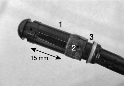
Head of the applicator. (1) Transducers. (2) Hole for the water cooling circuit. (3) Place for watertight seals.
Figure 2.
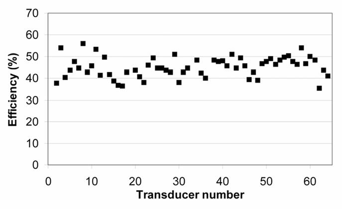
Efficiency of the transducers.
MR Imaging
Experiments were performed on a 1.5 T Philips ACS-NT clinical scanner (Philips Medical Systems, Best, Netherlands) equipped with a PT-6000 gradient system (gradient strength 23 mT/m, gradient slope 105 mT/m/ms). A 9 cm outer diameter C3 surface coil (Philips Medical Systems, Best, Netherlands), running at 64 MHz, was used to receive the MRI signals. Magnitude and phase images were transferred on-line from the scanner to the workstation using software supplied by Philips Medical Systems.
METHODS
MRI compatibility of the applicator
An initial series of experiments was performed to verify the applicator compatibility with the MR clinical scanner. The applicator was embedded in a 1% Agar gel. The applicator was oriented successively parallel and perpendicular to the static field B0 for each MR sequence. First, anatomic images were produced using a turbo spin echo (TSE) sequence (TR=800 ms; TE=20 ms; flip angle=90°; slice thickness=6 mm; field of view (FOV) 128×128 mm2). Second, a fast field echo sequence (commonly used for temperature mapping) was applied (TR=500 ms; TE=21 ms; flip angle=35°; slice thickness=3 mm; FOV=128×128 mm2).
Since the device will be in contact with the tumours during treatment, the view of the tissular structure in contact with and close to the applicator must be free of magnetic susceptibility artefacts and radiofrequency interference. Thus, a second series of tests was performed ex vivo using 10 fresh liver samples. The water used for all experiments was deoxygenated to less than 0.1 mg O2/L. The liver was cut into samples approximately 50×30×50 mm3 in size and placed in a plastic cylinder (outer diameter 60 mm; height 120 mm) filled with degassed water thermostatically maintained at 37°C. This cylinder was pierced with a 10 mm diameter hole, to allow for passage of the applicator which was positioned in the middle of the tissues. Before starting experiments, a thermocouple was inserted in the sample until the temperature of tissue was close to 37°C. The MRI signal receiver was placed around the cylindrical tank, about 1 cm above the applicator (figure 3). In order to make sure that the applicator could be placed in contact with the tissues to be treated without performing susceptibility artefacts or radiofrequency interference, T2-weighted spin echo sequences (TR=2000 ms; TE=100 ms; field of view 96×96 mm2; slice thickness 3.9 mm; slice gap 0.1 mm; flip angle 90°) and T1-IR sequences (TR=2000 ms; TE=8 ms; TI=250 ms; field of view 96×96 mm2; slice thickness 3.9 mm; slice gap 0.1 mm; flip angle 90°) were applied.
Figure 3.

Experimental system and electrical equipment for in vitro experiments.
Monitoring thermal treatments
PRF-based MR-thermometry was used in this work, as the PRF-shift temperature coefficient is constant and tissue-type independent over the full temperature range of interest for an ultrasound treatment34. Fast gradient echo, segmented EPI sequences were used (single slice, axial orientation, 8 mm thick, TR/TE=250/16 ms, flip angle 35°, 15 lines/TR, acquisition matrix 128 × 120, field of view 200×200 mm2) and the temporal resolution was approximately 3s/image. MR thermometry was always performed with the applicator in situ and the water balloon inflated (O.D. of approximately 20 mm) for normal operation of the ultrasound device. Relative phase map were temporally unwrapped, then the phase difference with respect to the reference map (a temporal average on first eight scans) was converted into a temperature rise using a PRF temperature dependence of 0.01 ppm/°C17.
Before sonication, the stability of the temperature baseline was verified in all the voxels distributed around the ultrasound applicator in the first tissue layers (approximately 1–2 mm deep) and in deep liver tissues, approximately 10 mm from the ultrasound transducer. Water circulation was started 5 seconds before the MR acquisition. Water flow continued during MR acquisition in order to avoid possible transducer overheating. A single slice acquisition was used for MR thermometry, and the main water stream was perpendicular to this slice. The average stream velocity inside the balloon was relatively low (approximately 10 mm/s, laminar regime). Therefore, the distance moved by water over the period from the RF pulse until the end of the echo train acquisition was approximately 0.3 mm, which is much smaller than the slice thickness (8 mm). No significant flow artefact should be expected under such conditions, and this was never detected experimentally.
Temperature maps were displayed on-line using Thermoguide software (IGT SA, Pessac, France). At relatively high temperatures (~55–60°C), cell death occurs via thermal coagulation, even when the exposure time is short. Such temperatures will likely be the desired endpoint for guiding thermal therapies to ensure with confidence that the target tissue is killed. However, it is known from hyperthermia studies that tissue damage can occur at substantially lower temperatures, depending on the heating time. The accumulated effects of such low-level heating need to be taken into account to protect normal tissue near the target volume. These effects will be important near the edge of the thermal lesion. Thus the thermal dose, a nonlinear function of the temperature and time described by Sparato and Dewey 35, was computed by the Thermoguide software during thermometry:
t43 is the thermal dose in equivalent min at 43°C, T is the average temperature during time Δt and R is a constant that equals 0.5 above 43°C and 0.25 below 43°C. Temperature and thermal dose maps were displayed on-line simultaneously during each ultrasound exposure. Tissues were considered as coagulated if the equivalent time at 43°C is 120 minutes or higher36.
Tests were performed ex vivo on 47 samples of pig liver. Exposure conditions and corresponding sequence names are given in Table 1. Each elementary lesion was induced by exciting a group of eight adjacent transducers with appropriate delay time (0, 100, 170, 200, 200, 170, 100 and 0 ns for transducers 1 to 8 respectively) such as a plane wave can be generated. These values were determined in a preliminary study where phase off-sets at the amplifier channel and at each transducer sector were determined from hydrophone measurements32. Acoustic intensities were set to 12, 15, 17 and 20 W/cm2 (spatial average at the surface of the transducer) for a constant time of exposure: 90 seconds. Power levels were adjusted to keep acoustic intensities of each sector constant according to measured force-balance acoustic power. Electronic rotation of the ultrasound beam was performed between two consecutive exposures. The time between two consecutive exposures was set to 20 seconds in order to visualize diffusion effects on temperature maps. Thirty-two sonications were performed with 12°-increments of electronic angular rotation to create cylindrical lesions. Two sonications (sequence F) were performed with 90°-increments to clearly observe electronic angular rotation on the MR temperature maps. Exposure conditions come from our experience in the treatment of biliary and oesophageal cancers in terms of thermal ablation with miniature nonfocused transducers30,37. In order to make comparisons, five lesions were produced by generating cylindrical waves. Eight elements of the cylindrical array were excited with no delay. The acoustic intensity for all the transducers was 20 W/cm2 and the exposure time was 90 seconds.
Table 1.
Description of the different sequences of treatment. The time of exposure was set to 90 seconds for all elementary sonication.
| Sequence | Number of samples | Number of exposures in each sample | Angular step between two exposures (°) | Intensity (W/cm2) |
|---|---|---|---|---|
| A | 4 | 32 | 12 | 12 |
| B | 4 | 32 | 12 | 15 |
| C | 6 | 32 | 12 | 17 |
| D | 5 | 4 | 90 | 20 |
| E | 7 | 32 | 12 | 20 |
| F | 4 | 2 | 90 | 15 and 20 |
| G | 4 | 2 | 0 | 15 |
| H | 8 | 9 | 6 | 12 and 17* |
12 W/cm2 for the exposures 1–4 and 17 W/cm2 for exposures 5–9.
Samples were frozen just after treatment to make the lesion easier to cut and examine. When the tissue temperature was close to −6°C, the tissues were sliced along a plane perpendicular to the applicator axis situated at midheight from the transducer. The dimensions of the necroses were measured visually and compared with those determined from the thermal dose computed during treatment.
RESULTS
MRI compatibility of the applicator
All MR acquisitions were performed without susceptibility artefacts or radiofrequency interferences with the ultrasound device. Figure 4 shows the applicator in the Agar gel block using TSE sequences. The diameter of the applicator measured on these figures is 10.5 mm, which is close to the actual diameter (10.6 mm). Figure 5 shows the applicator in the Agar gel block using fast gradient echo sequences. The diameter of the applicator is 10.8 mm, which is also close to the actual diameter. There were no artefacts or radiofrequency interferences around the ultrasound device. Figures 6a and 6b show T2w and T1-IR images of the device in the longitudinal plane. The balloon is inflated around the applicator. The tissues close to the applicator can be displayed without magnetic susceptibility atefeacts.
Figure 4.
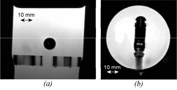
Applicator embedded in Agar gel block viewed with turbo spin echo sequences. TR=800 ms; TE=20 ms; flip angle=90°; slice thickness=6 mm; field of view (FOV) 128×128 mm2 (a) Longitudinal plane. (b) Axial plane.
Figure 5.
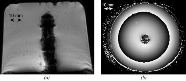
Applicator embedded in Agar gel block viewed in transverse plane with fast gradient echo sequences. TR=500 ms; TE=21 ms; flip angle=35°; slice thickness=3mm; field of view 128×128 mm2. (a) Magnitude. (b) Phase. The applicator is in the centre of the figure.
Figure 6.
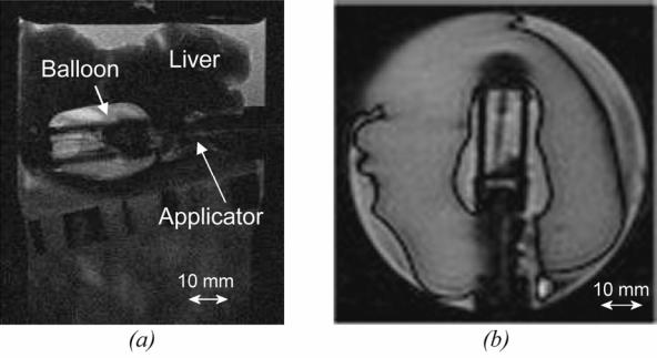
(a) T2w image of the ultrasound device (longitudinal plane) inserted in a sample of pig liver. (b) T1-IR image of the ultrasound device (longitudinal plane). The balloon is inflated around the applicator.
Monitoring thermal treatments
The best phase stability was achieved in deep liver tissues, approximately 10 mm from the transducer. The average value was 0.3°C (±0.6°C, range: −0.7°C to 1°C). Maximum fluctuations correspond to the first tissue layers. The average value was 0.8°C (±1.2°C, range: −1.3°C to 2.1°C). These values were acquired before sonication in 32 voxels located in the first tissue layers. Figures 7a to 7h show temperature maps obtained during sequence F. The first exposure was performed with an acoustic intensity of 15 W/cm2 (figures 7a to 7c). The second exposure was performed with an acoustic intensity of 20 W/cm2 (figures 7d to 7g). As expected the heat deposition occurs with the shape of a parallelepiped rectangle with a depth that could be varied by adjusting the intensity of exposure. This shape corresponds to the absorption of a plane wave38. Figure 7h shows thermal diffusion following the sonication. Figure 8 shows the temperature time course for two successive sonications along the same direction (sequence G). Three locations (every 4.5 mm) along the acoustic axis of the recreated plane wave were considered. The standard deviation in the data is about 4%. Figures 9a to 9d shows several temperature maps obtained during one exposure of sequence D. Figure 9A to 9D shows the corresponding thermal dose maps computed simultaneously during sonications.
Figure 7.
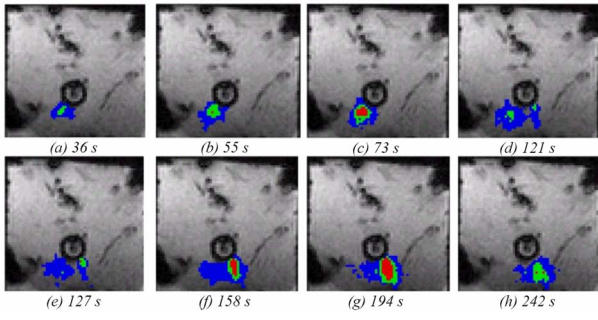
Temperature monitoring in a transverse plane during two ultrasound exposures (sequence F). Colour map: red above 52°C, green 47 to 52 °C, blue 42 to 47°C.
Figure 8.
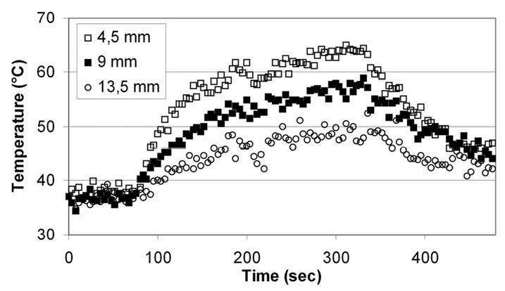
Temperature time course for two successive sonications along the same direction (sequence G). Three locations along the acoustic axis were considered.
Figure 9.

(a to d) Temperature and (A to D) equivalent time at 43°C (thermal dose) monitoring in a transverse plane during sequence D.
(a to d) colour map: red above 52°C, green 47 to 52°C, blue 42 to 47°C.
(A to D) colour map: red above 20 hours equivalent time at 43°C, green 2 hours equivalent time at 43°C, blue 1 hour equivalent time at 43°C.
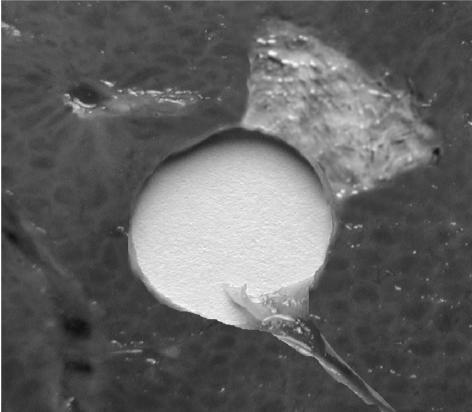
All the lesions had well-defined borders and were reproducible. Cuts perpendicular to the axis of the applicator (figure 10a and 10b) allowed measurement of the radius of the coagulation necrosis volumes, which represent the maximal lesion depth along the acoustic axis. This cross-section demonstrates that the therapeutic depth of a cylindrical coagulation necrosis is constant around the applicator. Figure 10a shows a typical lesion induced by sequence C. Figure 10b shows a typical lesion obtained by varying the power emitted according to the angular position (sequence H). Edges of the coagulated area are well-delimited and the angle of treatment is 90°. The mean, minimal and maximal values of the treatment depth are given in figure 11 as a function of intensity for constant exposure duration (sequences A, B, C and E). The depths of the lesions were reproducible with a standard deviation of less than 5%. Cylindrical lesions, up to 17 mm-deep can be induced by applying 20 W/cm2 for 90s. Table 2 shows the individual differences between measurements performed visually and using MRI thermal dose maps. The measurements are in good agreement. Average values of the ablated region for single exposures predicted by imaging were 79.2 mm2 (18.0×4.4) and 70.5 mm2 (17.2×4.1) for the volume measured visually after dissection. This is a 11 % difference, mainly due to the uncertainty of visual measurement. Figure 12 shows a lesion obtained by simultaneously exciting eight elements. The lesion covered 45 degrees and extended down to a depth of 8±1 mm. The height of the thermal damage was considered as being the same as the height of the transducers39 (15 mm).
Figure 10.
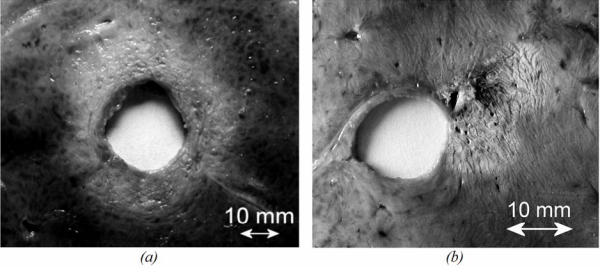
Liver tissue treated ex vivo (section perpendicular to the axis of the applicator). (a) using sequence C. (b) using sequence H.
Figure 11.
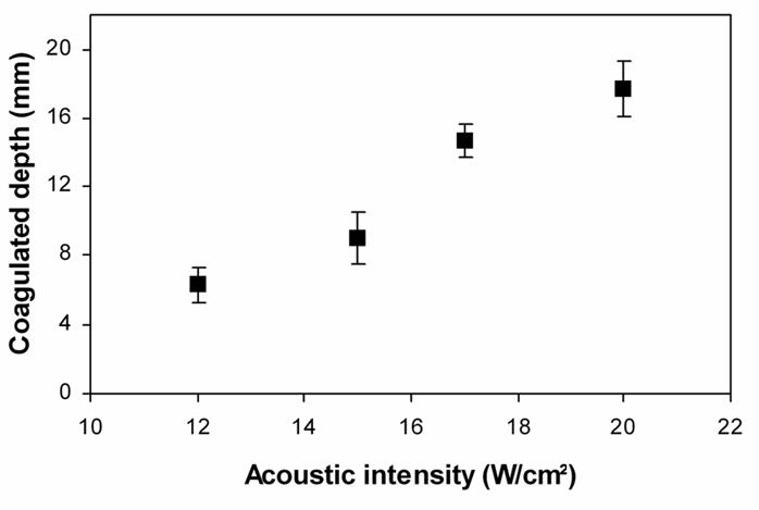
Mean, minimal and maximal values of the treatment depth for circular lesions in function of the acoustical intensity (sequences A, B, C, E).
Table 2.
Comparison of lesion size between MRI and visual inspection. Minimal, average and maximal values across twenty elementary lesions (sequence E).
| MRI | Visual inspection | |||||
|---|---|---|---|---|---|---|
| Min | Average | Max | Min | Average | Max | |
| Width (mm) | 4.0 | 4.4 | 4.8 | 4.0 | 4.1 | 5.0 |
| Depth (mm) | 17.2 | 18.0 | 19.0 | 16.0 | 17.2 | 18.0 |
Figure 12.
Lesion obtained by exciting eight transducers with the same phase (20 W/cm2 - 90 seconds).
DISCUSSION
This new ultrasound applicator is designed for intraluminal use and is compatible with MRI clinical scanners. All MR acquisitions were performed without susceptibility artefacts or radiofrequency interferences with the ultrasound device. The tissues in contact with and close to the applicator can be displayed without magnetic susceptibility artefacts and it may be possible to clearly visualize the edges of the tumour to be treated in clinical applications. Phase stability measurements and trials carried out with the applicator embedded in an Agar gel illustrate full compatibility with MRI “real-time” temperature mapping. Heat deposition can be measured close to the transducer with an accuracy of 0.8°C as shown by in vitro experiments. It is important to be able to measure temperature close to the transducer if this method is used for clinical treatment since, in this case, the oesophageal lumen is obstructed and the applicator will be in contact with the tumour.
The main advantage of an MRI compatible device is to use PRF based MR thermometry to monitor thermal therapy. Several existing ultrasound applicators require mechanical movements during treatment to treat the whole region of interest. Motion of the device during MR-thermometry can induce inhomogeneities in the static field which could lead to false temperature estimates. To avoid that, MR-thermometry sequences can be stopped after the end of each ultrasound exposure and the temperature baseline has to be checked after the displacement of the ultrasound device. A new reference phase map has to be defined for each ultrasound exposure. This procedure can lead to long treatment time. The device described in this paper can perform treatments without mechanical movements. The location of the heated region can be rotated without mechanical displacement. The time of treatment is then significantly reduced and MR-thermometry may be performed continuously during treatment with accurate temperature monitoring. Since a 4.6 MHz ultrasound beam propagates fairly far in tissue careful attention will be paid to surrounding tissue (bone, gas interface …) using MR temperature monitoring.
All the lesions induced ex vivo were reproducible. The coagulated tissues were clearly distinguishable from untreated tissue; the lesion has an off-white colour, sometimes dark at the most heated points. The greatest coagulated depth was about 17 mm for an acoustic intensity of 20 W/cm2 with a sonication time of 90 seconds. This treatment depth would be sufficient for treating oesophageal tumours (the thickness of which varies from three to twelve millimetres in most cases). Although the sonications time are long, the depths of ex vivo and in vivo thermal damage would be close together in the oesophagus because the effect of blood flow in this organ is a minor factor when it comes to lesion formation37. However, the depth of lesions may change with perfused tumours. In this case, power levels to each sector will be adjusted according to MR-temperature monitoring and MR estimation of the necrotic area.
Furthermore, these ex vivo experiments show that electronic rotation of the applicator makes it possible to induce coagulation necrosis with well-defined shapes. The difference between the angle chosen and the angle experimentally obtained was no greater than ±3°, meaning that sector-based tumours can be treated accurately. The difference between the planned treatment angle and the observed result can be explained by thermal diffusion (the heat delivered beyond the treatment margin) due to long exposure duration and by uncertainty of measurement.
As has been experimentally demonstrated, when all eight elements are excited in phase, the necrosis obtained is much more superficial (8 mm) because of divergence of the ultrasound beam. Although the possibility of using diverging beam with increased acoustic intensity to treat areas deeper than 8 mm might be of interest to reduce the treatment time, in our experiment we restricted ourselves to a power of 20 W/cm² to avoid damaging the transducer elements. Thus, if the depth of a local tumour extends less than 8 mm it may be possible to treat all the malignant cells in a single exposure. In this case, the number of the active transducers must be adjusted for the area involved. However, if the depth of a local tumour extends beyond 8 mm it is necessary to use plane waves.
The difference between the ablation volume predicted by imaging and the volume measured after dissection is 11 % which is satisfactory since the accuracy of the ultrasound treatment is about 1 mm32. This difference is mainly due to the uncertainty of visual measurement. In addition, there is probably uncertainty in the use of t43=120 minutes as defining a boundary of visible thermal coagulation in perfused tissue. A larger and more detailed study involving in vivo measurements in soft tissue, correlated with gross and histopathologic findings, could determine more accurately the correlation between the ablation volume predicted by imaging and the actual extent of ablated regions of tissues. Other possible sources of error include noise in the MR temperature maps, uncertainty in the baseline temperature and other possible errors in the temperature mapping40. Even with the combination of all of these uncertainties, the MRI-derived thermal dose information was provided simultaneously during the exposures and was proved to be a good predictor for tissue damage41,42.
For in vivo studies in the oesophagus and clinical implementation, the MRI signal would be acquired by synchronising the acquisition with breathing and cardiac signals to correct for tissue motion during MRI temperature monitoring29. In addition, suppression of flow artefacts from large vessels in the vicinity of the tumour would improve the stability of PRF thermometry.
In conclusion, this work enabled us to study and develop an intraluminal ultrasound cylindrical phased array with 64 elements. This applicator, designed for the treatment of oesophageal cancers is fully compatible with use in a magnetic resonance imaging environment and other sites of the digestive duct like colorectal cancer may be treated with this applicator technology. It was also shown that the electronic apparatus controlling the transducers provides electronic rotation of the ultrasound beam, which ensures precise spatial control of the deposited power. The principle of the plane rotating beam makes it possible to adjust the treatment depth according to the angular position of the region to be treated by using different power levels or different sonication time.
References
- 1.Inoue H, Tani M, Nagai K, Kawano T, Takeshita K, Endo M, Iwai T. Treatment of esophageal and gastric tumors. Endoscopy. 1999;31:47–55. doi: 10.1055/s-1999-13647. [DOI] [PubMed] [Google Scholar]
- 2.Coia LR, Minsky BD, Berkey BA, John MJ, Haller D, Landry J, Pisansky TM, Willett CG, Hoffman JP, Owen JB, Hanks GE. Outcome of patients receiving radiation for cancer of the esophagus: results of the 1992–1994 Patterns of Care Study. J Clin Oncol. 2000;18:455–462. doi: 10.1200/JCO.2000.18.3.455. [DOI] [PubMed] [Google Scholar]
- 3.De Palma GD, di Matteo E, Romano G, Fimmano A, Rondinone G, Catanzano C. Plastic prosthesis versus expandable metal stents for palliation of inoperable esophageal thoracic carcinoma: a controlled prospective study. Gastrointest Endosc. 1996;43:478–482. doi: 10.1016/s0016-5107(96)70290-0. [DOI] [PubMed] [Google Scholar]
- 4.Konigsrainer A, Riedmann B, De Vries A, Ofner D, Spechtenhauser B, Aigner F, Fritsch E, Margreiter R. Expandable metal stents versus laser combined with radiotherapy for palliation of unresectable esophageal cancer: a prospective randomized trial. Hepatogastroenterology. 2000;47:724–727. [PubMed] [Google Scholar]
- 5.Gelet A, Chapelon JY, Poissonnier L, Bouvier R, Rouviere O, Curiel L, Janier M, Vallancien G. Local recurrence of prostate cancer after external beam radiotherapy: early experience of salvage therapy using high-intensity focused ultrasonography. Urology. 2004;63:625–629. doi: 10.1016/j.urology.2004.01.002. [DOI] [PubMed] [Google Scholar]
- 6.Illing RO, Kennedy JE, Wu F, ter Haar GR, Protheroe AS, Friend PJ, Gleeson FV, Cranston DW, Phillips RR, Middleton MR. The safety and feasibility of extracorporeal high-intensity focused ultrasound (HIFU) for the treatment of liver and kidney tumours in a Western population. Br J Cancer. 2005;93:890–895. doi: 10.1038/sj.bjc.6602803. [DOI] [PMC free article] [PubMed] [Google Scholar]
- 7.Jolesz FA, Hynynen K, McDannold N, Tempany C. MR imaging-controlled focused ultrasound ablation: a noninvasive image-guided surgery. Magn Reson Imaging Clin N Am. 2005;13:545–560. doi: 10.1016/j.mric.2005.04.008. [DOI] [PubMed] [Google Scholar]
- 8.Ross AB, Diederich CJ, Nau WH, Rieke V, Butts RK, Sommer G, Gill H, Bouley DM. Curvilinear transurethral ultrasound applicator for selective prostate thermal therapy. Med Phys. 2005;32:1555–1565. doi: 10.1118/1.1924314. [DOI] [PubMed] [Google Scholar]
- 9.Chopra R, Bronskill MJ, Foster FS. Feasibility of linear arrays for interstitial ultrasound thermal therapy. Med Phys. 2000;27:1281–1286. doi: 10.1118/1.599006. [DOI] [PubMed] [Google Scholar]
- 10.Makin IR, Mast TD, Faidi W, Runk MM, Barthe PG, Slayton MH. Miniaturized ultrasound arrays for interstitial ablation and imaging. Ultrasound Med Biol. 2005;31:1539–1550. doi: 10.1016/j.ultrasmedbio.2005.07.008. [DOI] [PubMed] [Google Scholar]
- 11.Cain C, Umemura SI. Concentric-ring and sector-vortex phased-array applicators for ultrasound hyperthermia. IEEE Trans Microwave Theory Tech. 1999;44:1803–1813. [Google Scholar]
- 12.Curiel L, Chavrier F, Souchon R, Birer A, Chapelon JY. 1.5-D high intensity focused ultrasound array for non-invasive prostate cancer surgery. IEEE Trans Ultrason Ferroelectr Freq Control. 2002;49:231–242. doi: 10.1109/58.985707. [DOI] [PubMed] [Google Scholar]
- 13.Hynynen K, Clement GT, McDannold N, Vykhodtseva N, King R, White PJ, Vitek S, Jolesz FA. 500-element ultrasound phased array system for noninvasive focal surgery of the brain: a preliminary rabbit study with ex vivo human skulls. Magn Reson Med. 2004;52:100–107. doi: 10.1002/mrm.20118. [DOI] [PubMed] [Google Scholar]
- 14.Fan X, Hynynen K. A study of various parameters of spherically curved phased arrays for noninvasive ultrasound surgery. Phys Med Biol. 1996;41:591–608. doi: 10.1088/0031-9155/41/4/002. [DOI] [PubMed] [Google Scholar]
- 15.ter Haar G, Sinnett D, Rivens I. High intensity focused ultrasound--a surgical technique for the treatment of discrete liver tumours. Phys Med Biol. 1989;34:1743–1750. doi: 10.1088/0031-9155/34/11/021. [DOI] [PubMed] [Google Scholar]
- 16.Tempany CM, Stewart EA, McDannold N, Quade BJ, Jolesz FA, Hynynen K. MR imaging-guided focused ultrasound surgery of uterine leiomyomas: a feasibility study. Radiology. 2003;226:897–905. doi: 10.1148/radiol.2271020395. [DOI] [PubMed] [Google Scholar]
- 17.Peters RD, Hinks RS, Henkelman RM. Ex vivo tissue-type independence in proton-resonance frequency shift MR thermometry. Magn Reson Med. 1998;40:454–459. doi: 10.1002/mrm.1910400316. [DOI] [PubMed] [Google Scholar]
- 18.Vimeux FC, de Zwart JA, Palussière J, Fawaz R, Delalande C, Canioni P, Grenier N, Moonen CTW. Real-time control of focused ultrasound heating based on rapid MR thermometry. Invest Radiol. 1999;34:190–193. doi: 10.1097/00004424-199903000-00006. [DOI] [PubMed] [Google Scholar]
- 19.Puccini S, Bar NK, Bublat M, Kahn T, Busse H. Simulations of thermal tissue coagulation and their value for the planning and monitoring of laser-induced interstitial thermotherapy (LITT) Magn Reson Med. 2003;49:351–362. doi: 10.1002/mrm.10357. [DOI] [PubMed] [Google Scholar]
- 20.Fei B, Duerk JL, Boll DT, Lewin JS, Wilson DL. Slice-to-volume registration and its potential application to interventional MRI-guided radio-frequency thermal ablation of prostate cancer. IEEE Trans Med Imaging. 2003;22:515–525. doi: 10.1109/TMI.2003.809078. [DOI] [PubMed] [Google Scholar]
- 21.Wetzel FT, McNally TA, Phillips FM. Intradiscal electrothermal therapy used to manage chronic discogenic low back pain: new directions and interventions. Spine. 2002;27:2621–2626. doi: 10.1097/00007632-200211150-00043. [DOI] [PubMed] [Google Scholar]
- 22.Morikawa S, Inubushi T, Kurumi Y, Naka S, Sato K, Tani T, Yamamoto I, Fujimura M. MR-guided microwave thermocoagulation therapy of liver tumors: initial clinical experiences using a 0.5 T open MR system. J Magn Reson Imaging. 2002;16:576–583. doi: 10.1002/jmri.10198. [DOI] [PubMed] [Google Scholar]
- 23.Hynynen K, McDannold N, Sheikov NA, Jolesz FA, Vykhodtseva N. Local and reversible blood-brain barrier disruption by noninvasive focused ultrasound at frequencies suitable for trans-skull sonications. Neuroimage. 2005;24:12–20. doi: 10.1016/j.neuroimage.2004.06.046. [DOI] [PubMed] [Google Scholar]
- 24.Palussiere J, Salomir R, Le Bail B, Fawaz R, Quesson B, Grenier N, Moonen CT. Feasibility of MR-guided focused ultrasound with real-time temperature mapping and continuous sonication for ablation of VX2 carcinoma in rabbit thigh. Magn Reson Med. 2003;49:89–98. doi: 10.1002/mrm.10328. [DOI] [PubMed] [Google Scholar]
- 25.Pisani LJ, Ross AB, Diederich CJ, Nau WH, Sommer FG, Glover GH, Butts K. Effects of spatial and temporal resolution for MR image-guided thermal ablation of prostate with transurethral ultrasound. J Magn Reson Imaging. 2005;22:109–118. doi: 10.1002/jmri.20339. [DOI] [PubMed] [Google Scholar]
- 26.Bihrle R, Foster RS, Sanghvi NT, Fry FJ, Donohue JP. High-intensity focused ultrasound in the treatment of prostatic tissue. Urology. 1994;43:21–26. doi: 10.1016/0090-4295(94)90214-3. [DOI] [PubMed] [Google Scholar]
- 27.Nau WH, Diederich CJ, Ross AB, Butts K, Rieke V, Bouley DM, Gill H, Daniel B, Sommer G. MRI-guided interstitial ultrasound thermal therapy of the prostate: a feasibility study in the canine model. Med Phys. 2005;32:733–743. doi: 10.1118/1.1861163. [DOI] [PubMed] [Google Scholar]
- 28.Chopra R, Luginbuhl C, Weymouth AJ, Foster FS, Bronskill MJ. Interstitial ultrasound heating applicator for MR-guided thermal therapy. Phys Med Biol. 2001;46:3133–3145. doi: 10.1088/0031-9155/46/12/305. [DOI] [PubMed] [Google Scholar]
- 29.Melodelima D, Salomir R, Chapelon JY, Theillere Y, Moonen C, Cathignol D. Intraluminal high intensity ultrasound treatment in the esophagus under fast MR temperature mapping: in vivo studies. Magn Reson Med. 2005;54:975–982. doi: 10.1002/mrm.20638. [DOI] [PubMed] [Google Scholar]
- 30.Prat F, Lafon C, Melodelima D, Theilliere Y, Fritsch J, Pelletier G, Buffet C, Cathignol D. Endoscopic treatment of cholangiocarcinoma and carcinoma of the duodenal papilla by intraductal high-intensity US: Results of a pilot study. Gastrointest Endosc. 2002;56:909–915. doi: 10.1067/mge.2002.129872. [DOI] [PubMed] [Google Scholar]
- 31.Prat F, Lafon C, Melodelima D, Theillere Y, Cathignol D. Intraductal ultrasound for the treatment of digestive tumours: First clinical results. Third international symposium on therapeutic ultrasound; Lyon, France. 2003. pp. 145–150. [Google Scholar]
- 32.Melodelima D, Lafon C, Prat F, Birer A, Cathignol D. Ultrasound cylindrical phased array for transoesophageal thermal therapy: initial studies. Physics in Medicine and Biology. 2002;47:4191–4203. doi: 10.1088/0031-9155/47/23/306. [DOI] [PubMed] [Google Scholar]
- 33.Hill CR. Calibration of ultrasonic beams for bio-medical applications. Phys Med Biol. 1970;34:1743–1750. doi: 10.1088/0031-9155/15/2/001. [DOI] [PubMed] [Google Scholar]
- 34.Ishihara Y, Calderon A, Watanabe H, Okamoto K, Suzuki Y, Kuroda K, Suzuki Y. A precise and fast temperature mapping using water proton chemical shift. Magn Reson Med. 1995;34:814–823. doi: 10.1002/mrm.1910340606. [DOI] [PubMed] [Google Scholar]
- 35.Saparato SA, Dewey WC. Thermal dose determination in cancer therapy. Int J Radiat Oncol Phys. 1984;10:803–813. doi: 10.1016/0360-3016(84)90379-1. [DOI] [PubMed] [Google Scholar]
- 36.Damianou C, Hynynen K, Fan X. Evaluation of accuracy of a theoretical model for predicting the necrosed tissue volume during focused ultrasound surgery. IEEE Trans Ultrason Ferroelectr Freq Control. 1995;42:182–187. [Google Scholar]
- 37.Melodelima D, Lafon C, Prat F, Theillere Y, Arefiev A, Cathignol D. Transoesophageal ultrasound applicator for sector-based thermal ablation: first in vivo experiments. Ultrasound in Medicine and Biology. 2003;29:285–291. doi: 10.1016/S0301-5629(02)00701-9. [DOI] [PMC free article] [PubMed] [Google Scholar]
- 38.Melodelima D, Chapelon JY, Theillere Y, Cathignol D. Combination of thermal and cavitation effects to generate deep lesions with an endocavitary applicator using a plane transducer: ex vivo studies. Ultrasound in Medicine and Biology. 2004;30:103–111. doi: 10.1016/j.ultrasmedbio.2003.09.005. [DOI] [PubMed] [Google Scholar]
- 39.Lafon C, Chapelon JY, Prat F, Gorry F, Theillere Y, Cathignol D. Design and in vitro results of a high intensity ultrasound interstitial applicator. Ultrasonics. 1998;36:683–687. doi: 10.1016/s0041-624x(97)00139-x. [DOI] [PubMed] [Google Scholar]
- 40.Peters RD, Chan E, Trachtenberg J, Jothy S, Kapusta L, Kucharczyk W, Henkelman RM. Magnetic resonance thermometry for predicting thermal damage: an application of interstitial laser coagulation in an in vivo canine prostate model. Magn Reson Med. 2000;44:873–883. doi: 10.1002/1522-2594(200012)44:6<873::aid-mrm8>3.0.co;2-x. [DOI] [PubMed] [Google Scholar]
- 41.Hazle JD, Stafford RJ, Price RE. Magnetic resonance imaging-guided focused ultrasound thermal therapy in experimental animal models: correlation of ablation volumes with pathology in rabbit muscle and VX2 tumors. J Magn Reson Imaging. 2002;15:185–194. doi: 10.1002/jmri.10055. [DOI] [PubMed] [Google Scholar]
- 42.Graham SJ, Chen L, Leitch M, Peters RD, Bronskill MJ, Foster FS, Henkelman RM, Plewes DB. Quantifying tissue damage due to focused ultrasound heating observed by MRI. Magn Reson Med. 1999;41:321–328. doi: 10.1002/(sici)1522-2594(199902)41:2<321::aid-mrm16>3.0.co;2-9. [DOI] [PubMed] [Google Scholar]