Abstract
The axial deformation of a pipette-pressurized fluid membrane bag produces minuscule yet well-defined, reproducible forces. The stiffness of this ultrasensitive force transducer is tunable and largely independent of the constitutive membrane behavior. Based on a rigorous variational treatment, we present both numerical as well as approximate analytical solutions for the force-deflection relation of this unique biophysical force probe. Our numerical results predict a measurably nonlinear force-deflection behavior at moderate-to-large deformations, which we confirm experimentally using red blood cells. Furthermore, considering nearly spherical membrane shapes and enforcing proper boundary conditions, we derive an analytical solution valid at small deformations. In this linear regime the pressurized membrane bag behaves like a Hookean spring, with a spring constant that is significantly larger than previously published for the biomembrane force probe.
INTRODUCTION
Mechanical measurements based on “cellular forces”—that is, forces produced by axial deflection of a pipette-aspirated red blood cell—have been proposed as early as 1980 (1). This original idea led eventually to the development of the biomembrane force probe ((BFP) (2,3)). Since then, the BFP has been instrumental in the study of a variety of topical biophysical questions. Prominent examples include the single-molecule characterization of the dynamic strength of the biotin:streptavidin interaction (4), adhesion bonds formed by L-selectin (5), the P-selectin:PSGL-1 catch bond (6), and the homophilic binding strength of E-cadherin (7). Closely focusing on the functional context of biomolecular interactions, the BFP has been at the heart of our multiscale single-molecule/single-cell study of the mechanoregulation of PSGL-1-mediated neutrophil adhesion ((8–10); reviewed in Heinrich et al. (11)). In addition to characterizing bond dissociation under tensile forces, we also demonstrated the use of the BFP as a capable nanometer and piconewton indenter (12). Recently, the axial deformability of aspirated red blood cells allowed Pierrat and co-workers to inspect the static and dynamic interactions between cells and adhesive surfaces directly, i.e., without the intervening microsphere that is the probe tip of the BFP (13).
Despite the extensive use and remarkable success of the BFP, only few studies of the force-deflection relation of pipette-pressurized fluid membrane bags have been published. Most noteworthy is the thorough analysis by Simson and co-workers (3) that revealed a fairly small range of linear behavior of the BFP. That work was limited, however, to the case of tensile force application with the BFP, and its derivations were dauntingly complex. A rigorous and comprehensive analysis, especially one that is readily accessible to researchers working at the interface of biology, physics, and engineering, appears to be missing and is presented here. Using standard variational methods, and paying close attention to proper boundary conditions, we derive an exact numerical solution that can be implemented computationally with comparative ease. This numerical treatment encompasses the description of both “pulling” as well as “pushing” experiments. Its solution should serve as the “gold standard” against which approximate solutions have to be tested.
Our numerical solution also provides a suitable basis for the confident evaluation of the impact of nonlinearities in the force-deflection relation. We demonstrate the importance of such nonlinear effects by comparing our numerical calculations to preliminary experiments in which pipette-aspirated red cells were pushed against elastic beams (atomic force microscopy (AFM) cantilevers). When applied to the BFP at small deformations, however, our numerical solution does not reduce to the previously published BFP spring constant. Consequently, we derive an analytical approximation valid for nearly spherical cell shapes that agrees well with our numerical results in the linear regime, giving a corrected expression for the spring constant of the BFP.
The mechanical principle governing BFP operation applies generally to any fluid membrane bag, which we will simply call “cell” in what follows. We emphasize, however, that our derivations are only valid for fluid membranes enclosing a fluid cell interior. In other words, our results do not apply to cells with a highly viscous, three-dimensional cytoskeleton.
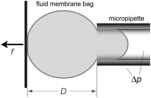
We consider a cell that is partially aspirated with suction pressure Δp in a glass micropipette (Fig. 1). (For a detailed tutorial on modern pipette aspiration, see Heinrich and Rawicz (14).) Opposite the pipette entrance, the cell is in circular contact with a surface that we assume to be flat here. The distance D between this surface and the pipette entrance represents the axial dimension of the free cell portion. In a pulling experiment this surface—usually of a functionalized glass bead—is retracted (f>0). This experiment is meaningful only if the cell membrane is chemically “glued” to the surface at the contact disk, which also means that the radius Rc of the contact disk is fixed in this case. If on the other hand f<0 (i.e., when pushing against the red cell), two scenarios are possible. In the first, Rc is still fixed at a constant value. This case corresponds to a flat-tipped cylindrical rod being pushed into the cell, creating a circular indentation. The second and practically more relevant case considers a cell that is pushed against an extended flat surface. In this case, the contact area is not fixed but depends on the cell deformation. (It should be mentioned that whenever Rc is larger than the pipette radius Rp, the membrane will also be pushed against the front face of the pipette. Our treatment can easily be extended to include this case; however, we will consider only deformations that are smaller here.)
FIGURE 1.
Sketch of a pipette-aspirated fluid membrane bag (“cell”) that is in contact with a flat surface (vertical thick solid line). The distance D between this surface and the pipette tip is adjustable, extending or compressing the cell along its symmetry axis.
Any pipette-pressurized cell resists deformations that displace D from its relaxed value. Establishing the relationship between the restoring force and the deflection ΔD is the main goal of this article. This task is simplified by our restriction to fluid membranes, allowing us to neglect any membrane resistance to shear. The very low bending resistance of the thin cell membrane, and the smallness of curvature changes accompanying the considered deformations, allow us to neglect bending contributions as well. On the other hand, the analysis is somewhat complicated by the geometric constraints of constant cell surface area and volume that need to be satisfied throughout the deformation.
Exact treatment and numerical solution
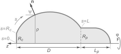
To determine the equilibrium shape of the free membrane, we minimize the total energy under the usual constraints of constant cell surface area and volume. The contour of the free membrane portion is described using the arc length s as independent variable. The distance of the contour from the z axis (axis of rotation) is ρ, and ψ denotes the angle between the surface normal n and the positive z-direction. For the definition of other geometric parameters, see Fig. 2. With this notation, the surface area and volume are given by
 |
(1) |
 |
(2) |
FIGURE 2.
Sketch defining the notation used in our numerical treatment. The angle ϕ is the azimuth of the axisymmetric arrangement; Rc is the radius of the circular contact disk, Rp the pipette radius, and Lp the projection length. For other symbols see the text.
The upper integration limit L is the total contour length along the free surface (including Rc; cf. Fig.2). The cell portion (“projection”) inside the pipette is taken to consist of a cylinder (of length Lp−Rp) and a hemispherical cap (of radius Rp). The axial extension D of the free part of the cell is simply
 |
(3) |
in this reference frame, and the principal curvatures of parallels and the meridian, cp and cm, are given by
 |
(4) |
Neglecting membrane bending and shear, the only relevant energy contributions during the considered deformation yield the following total energy:
 |
(5) |
 is the portion of cell volume that is moved by the (positive) aspiration pressure into the pipette. We eliminate the projection length Lp using the volume constraint V−V0 = 0. Then, incorporating the surface-area constraint A−A0 = 0 via a Lagrange multiplier σ (representing membrane tension) into a generalized energy functional
  we find (up to constant terms),
 |
(6) |
Λ is the Lagrange function for this energy functional; its dependence on  is implicit through the identity
  The boundary term
  is included here for completeness; it plays a role only if adhesive interactions between the cell and the flat surface are taken into consideration (see next section).
For the energy to be a minimum, necessary conditions are that the Euler-Lagrange equation
 |
(7) |
and the boundary conditions
 |
(8) |
be fulfilled (15), along with the constraint for the cell-surface area. The subscripts “p” and “c” in Eq. 8 denote the upper ( ) and lower (
 ) boundary of the free part of the cell, respectively. The minus sign corresponds to the partial derivative of B with respect to sc.
If the Lagrange function does not explicitly depend on s, as is the case here, the Euler-Lagrange equation (Eq. 7) can be integrated once to give  If at the same time a boundary for the independent variable s is movable (which is also the case here since the value of L is not known a priori, i.e.,
  whereas
  and
and  ), the respective natural boundary condition requires that the integration constant be zero. Hence, an alternative shape equation is the first integral
 |
(9) |
It is instructive to evaluate both shape equations Eqs. 7 and 9 by inserting the Lagrange function defined in Eq. 6, giving
 |
(10) |
and
 |
(11) |
respectively, where we have abbreviated a constant term
 |
(12) |
The two shape equations Eqs. 10 and 11 can be combined to give
 |
(13) |
Equation 13 confirms that the shape of the free membrane portion is a shape of constant mean curvature (1), with the mean curvature equal to the constant 1/R given by Eq. 12. The latter equation represents a particular form of Laplace's law for the present geometry. It is also easily seen from Eqs. 11 and 13 that in the absence of an axial force, both principal curvatures equal  which means that in this case the shape of the free cell portion is a sphere with radius
Equation 13 is actually more convenient than the lower-order differential equation Eq. 11 for the numerical calculation of cell shapes. It has to be integrated along with the equation that defines the relation between  and ψ. Additional (though noncoupled) differential equations need to be integrated to obtain the cell area, volume, and a version of the actual shape that can easily be plotted (e.g., in the form ρ(z)). We thus solve numerically the following system of ordinary differential equations:
 |
(Above, we have introduced A1 and V1 to denote the area (excluding the contact area  ) and the volume of the free cell portion, respectively.) Because we do not fix the orientation of the membrane at s = Rc, the initial natural boundary condition for the angle ψ is provided by the variational treatment itself. Here, it is conveniently given by Eq. 11. This is also the only place where the force f has entered the calculation so far.
The radius Rc of the circular contact disc is the initial value for the distance ρ from the symmetry axis. In experiments where Rc is fixed its value has to be measured directly. However, as mentioned in the Introduction, whenever the cell is pushed against a flat surface, the contact area is not fixed but depends on the cell deformation. Then  and the natural boundary condition Eq. 8 leads to
 |
(14) |
The first factor on the left-hand side of this boundary condition is equal to  (cf. Eq. 11). Therefore, both factors in the above product vanish simultaneously if ψc = 0, which is indeed the expected boundary angle whenever the cell is pushed against a flat surface. The variable contact radius in this case is given by
 |
(15) |
(Because f < 0 here, the square root is real.)
The above numerical integration is immersed in an iterative point-and-shoot wrapper that enforces fulfillment of the remaining boundary and auxiliary conditions. There are all together two such conditions in this problem. One is the constraint on the cell surface area (with Lp eliminated using the volume constraint); the other is the requirement that the free membrane connects continuously to the aspirated cell portion, i.e.,  To enforce these conditions, we iteratively correct the values of initial guesses for the only two parameters not fixed a priori by the variational problem, i.e., the curvature radius R and the contour length L.
Upon successful convergence of this iterative procedure, a final integration stores the shape of the free cell portion in the parametric form (z(s),ρ(s)) for later plotting if desired. Other quantities that are stored along with the given input values for A0, V0, Rp, Rc, Δp, and f, are the extension of the free part of the cell,  the projection length Lp (obtained from
  using the volume constraint Eq. 2), and the membrane tension σ (obtained from R using Eq. 12).
Additional energy contributions: area stretch and adhesion
The above framework can easily be extended to accommodate situations in which other energy contributions arise. We briefly address two such contributions: the elastic energy of membrane dilation, and the energy of adhesive interactions between the cell and the flat surface.
Our earlier assumption of constant surface area is a suitable approximation provided that changes in the aspiration pressure, and thus in the membrane tension, remain small throughout an experiment. However, if we vary the axial stiffness of the free part of a given cell by adjusting the aspiration pressure, the surface area will change to some extent. For a fluid membrane this area change is governed by the elastic energy of membrane dilation, σA. Formal replacement of the area constraint with this energy leads to the same equations as derived in the previous section. Therefore, to incorporate area stretch into our numerical procedure, we only need to modify the appropriate auxiliary condition. Where before we had iteratively adjusted the Lagrange multiplier σ to enforce the area constraint, we now adjust the membrane tension (again σ) to enforce the proper constitutive equation. In this case the constitutive equation is a two-dimensional, linear stress-strain relationship,
 |
(16) |
KA denotes the area-expansivity modulus of the fluid membrane. For red blood cells, for example,  (16). The reference area A(0) is the total area of the cell membrane in a tension-free state. For consistency, this reference area should be calculated from the constitutive equation using measured values of A and σ (given by Eq. 12) that were obtained at some initial aspiration pressure Δp (and f = 0).
Next, we consider adhesive interactions between the cell membrane and the flat surface. Such interactions play a major role, of course, in measurements that were specifically designed to characterize the dynamic strength of molecular adhesion (e.g., (13)). Other than that, a generic way to account for possible nonspecific surface interactions is generally useful in this experimental configuration.
We denote by γ the adhesive interaction energy per unit area and incorporate adhesion effects by adding the energy term  to the right-hand side of Eq. 6. This addition affects only the lower boundary condition (at
  ), because now
  All other equations remain the same, in particular, the shape equations Eqs. 10, 11, and 13. Inserting the new boundary term B(Rc) into the boundary condition Eq. 8 we find that Eq. 14 is now replaced by
 |
(17) |
Because the shape equation Eq. 11 still holds at the boundary, this becomes
 |
(18) |
As expected, this is the Young-Dupre equation for the contact angle ψc.
In the numerical treatment of this case, it is most practical to replace the previously used expression for the initial value of the angle ψ with the Young-Dupre boundary condition,  Then, the initial value
  can be obtained by solving Eq. 11 for ρ and inserting ψc into the result
 |
(19) |
This equation allows us to draw several interesting conclusions. For a zero contact angle (ψc = 0) we recover Eq. 15, consistent with a vanishing adhesion energy (γ = 0 as per Eq. 18). This case is meaningful only for pushing experiments (f < 0). More generally, when considering pushing experiments in the case of finite adhesion, Eq. 19 simply predicts how much the contact area increases due to the adhesion. In pulling experiments, however, there is a limited range of (positive) forces for which Rc assumes meaningful values, i.e.,
 |
(20) |
The upper bound f* of this force range corresponds to the smallest allowed contact radius of
 |
(21) |
Thus the contact area will not gradually shrink to a point as the pulling force increases. Instead, the cell will unbind from the surface at some finite contact radius  The critical unbinding radius, i.e., the radius where the (increasing) energy of the bound state (at increasing force) equals the energy of the unbound state, is actually even larger than
  Because the system may be kinetically trapped in the metastable, higher-energy state for some time, we generally expect to observe sudden unbinding at a value of Rc that lies between the critical radius and
Numerical results and comparison with experiments
We choose an example cell with the following dimensions (typical for a swollen red blood cell as used in the BFP) to demonstrate our baseline numerical analysis: 


 The subscript “0” stands for f = 0, i.e., an aspirated cell whose free portion is spherical. The total surface area of this cell is
  and its volume
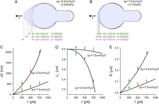
  Both quantities are assumed to remain constant during cell deformation. We model two pulling experiments (f≥0; fixed Rc) performed at aspiration pressures
  (
( ) and
) and  (
( ). Numerical results are presented in Fig. 3.
FIGURE 3.
Results of numerically modeled pulling experiments on cells with the same initial (f = 0) geometry but held at two different aspiration pressures Δp. The initial values of all geometric parameters are given in the text. (A,B) Contours of the two cells at four different pulling forces. (C) Deflection as a function of force for both cells (identified by their values of Δp). (D) Strongly nonlinear dependence of the projection length on force. (E) Radius of the constant mean curvature of the deformed cells as function of the pulling force. Colored arrows in panels C–E mark the locations of the respective contours of panels A and B.
The strong dependence of the cell's deformability on the pipette-aspiration pressure evident in Fig. 3 is what makes this system a force transducer with easily tunable stiffness. Given that we are able to detect reliably cell deflections as small as ∼5 nm in an optical microscope, we can “dial” the force resolution of this transducer down to a piconewton if desired. The pressure dependence of force manifests itself directly in the fact that for cells with the same initial (f = 0) geometry and the same deformation ΔD, the ratio Δp/f is a constant (see, for example, the case  in Fig. 3, A and B). However, this is only approximately true when pulling on the same cell at different aspiration pressures, because the membrane area and thus the f = 0 geometry depend on pressure, as discussed in the previous section.
This trivial relationship between pressure and force at given deformation does not, unfortunately, translate into a similarly simple relation between force and deflection at given aspiration pressure. Fig. 3 clearly illustrates the nonlinear behavior of geometric parameters during the modeled pulling experiments. It underlines that whenever considering moderate-to-large cell deflections, one should base the interpretation of experimental results on a numerical analysis such as presented here. Even when restricting experiments to small deformations, it is important to establish the range of the validity of linearized force-deflection relations, as well as the error associated with any such approximation.
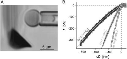
To demonstrate the application of our numerical analysis to nanomechanical experiments, we present preliminary results obtained with a novel force instrument that allowed us to push pipette-pressurized red blood cells against AFM cantilevers (Fig. 4 A). The cell-holding pipette was mounted to a closed-loop piezo-actuator and could be displaced with subnanometer resolution. Moving the pipette at constant speed, the cell was brought into contact with the flat of the cantilever at a well-defined distance from the cantilever tip. The deflection of the cantilever following contact yielded an accurate measurement of the axial deformation ΔD of the cell. (Details of the experimental setup are beyond the scope of this article and will be published elsewhere).
FIGURE 4.
(A) Videomicrograph of a pipette-aspirated red blood cell held close to the flat side of an AFM springboard cantilever. The side view of the ∼20-μm-wide cantilever creates a blurry diffraction pattern; only the cantilever tip (dark triangular shape) appears in focus. (B) Comparison of experimentally measured force-deflection curves to numerical predictions. At each of the three indicated pressures Δp, the nearly indistinguishable results of three successive compression experiments were plotted on top of each other (noisy curves). The overlaid smooth solid lines are numerical results obtained by setting the only adjustable quantity, i.e., the cantilever stiffness at the point of contact with the cell, to k = 7.1 pN/nm.
In the numerical analysis of this “pushing” experiment (f<0), the now-variable contact radius Rc was given by the natural boundary condition Eq. 15, in contrast to the “pulling” experiments (f≥0) modeled in Fig. 3. Furthermore, since we used the same cell with different aspiration pressures in successive pushing experiments, we have replaced the surface-area constraint with the elastic energy of area expansion (with modulus  ) in the analysis of the pushing experiment. Other than that, the numerical procedure to predict the cell deformation as a function of force is identical for pulling and pushing experiments.
Having measured all required geometric parameters from videomicrographs such as shown in Fig. 4 A, we determine the only adjustable quantity, i.e., the cantilever spring constant k, by matching numerical predictions to experimental results. Fig. 4 B reveals an excellent simultaneous agreement (matched here by eye; giving  ) between numerical results and nine nonlinear force-deflection curves measured at three different aspiration pressures Δp. Three nearly indistinguishable force-deflection curves were obtained at each of the three pressure values, demonstrating very good repeatability of this measurement. The value of k obtained at the cantilever position of cell contact corresponds to a spring constant of
  at the cantilever tip, well within the range of nominal spring constants (2–16 pN/nm) given by the manufacturer.
Nearly spherical shapes and the BFP spring constant
At sufficiently small deformations we may approximate nonlinear force-deflection curves such as shown in Fig. 3 C by straight lines that are the tangents to the original curves in the limit f→0. In this linear regime, a pipette-aspirated cell acts like a Hookean spring, which inspired the use of pressurized red blood cells as ultrasensitive biomembrane force probes in a number of nanomechanical experiments. Unfortunately, the initial slope of our numerical force-deflection curves does not reproduce the spring constant previously published for the BFP. In this section we present a rigorous derivation of the proper expression for this slope.
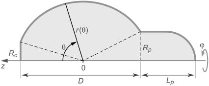
We restrict the analysis to the scenario with a fixed contact radius Rc (as is the case for the BFP). Since the free cell portion assumes a spherical shape at f = 0, we are seeking a linearized force-deflection relationship that is valid for cells whose free part is nearly spherical. We switch to spherical coordinates (Fig. 5) and expand the shape of the free cell portion in terms of the deviation u from a reference sphere. We are free to choose the radius of this sphere as long as we ensure that u is small in comparison. A suitable choice is the curvature radius R defined in Eq. 12. It simplifies the following analysis considerably; however, one has to keep in mind that due to its dependence on the tension σ (which is a function of the cell shape), R is itself an adjustable parameter. The shape of the free cell portion is thus described by  where u/R≪1.
FIGURE 5.
Sketch with notation for our analytical treatment of nearly spherical shapes of the free part of the cell. The polar angle θ is the independent variable. The shape is described by the distance r from the origin. The position of the origin is set by Eq. A11 of the Appendix.
We summarize the main steps of the derivation here and delegate details to the Appendix. The analysis broadly mirrors our exact treatment. Reexpressing the cell surface area, volume, axial extension, and total energy in terms of r(θ), we apply a second-order expansion in the perturbation u to the integrals giving the area and volume of the nearly spherical free cell portion (17). As before, we use the volume constraint to eliminate the projection length Lp and incorporate the remaining area constraint via the Lagrange multiplier σ into the generalized energy functional  finding up to constant terms,
 |
(22) |
The Lagrange function Λ is defined in Eq. A6 in the Appendix, whereas Eq. A7 gives the energy contribution B that depends only on the angles θc and θp, i.e., the θ-boundaries of the free cell part. Inserting the Lagrange function into the Euler-Lagrange equation, we recognize the resulting shape equation as the Legendre differential equation (with n = 1). Its general solution involves two integration constants, one of which we eliminate by placing the origin of the spherical coordinate system at the z-position where the contour's distance from the symmetry axis has an extremum (“equator”). The shape equation for the perturbation u then becomes
 |
(23) |
where the scaling factor C is the remaining integration constant. (C measures the deviation of the shape from the reference sphere at the equator.) Remarkably, in  we have thus found a quite simple, general analytical expression for a nearly spherical, axisymmetric shape of constant mean curvature 1/R.
As before, the force f enters the calculations through the boundary condition. For the energy functional of Eq. 22, the boundary condition takes the form
 |
(24) |
where 
 and the minus sign corresponds to the partial derivative of B with respect to θc. Neither the boundary angles θp,c nor the perturbations up,c at the boundaries are fixed in the current variational problem; however, with constant Rc and Rp, they are interconnected through
 |
(25) |
Therefore,  and since
  the natural boundary condition requires that
 |
(26) |
Equation 26 is the fourth equation needed to evaluate the four unknowns R, C, θp, and θc at equilibrium. The other three equations are the two boundary relations in Eq. 25 and the surface-area constraint. Because we are only interested in the slope of the force-deflection relation at f = 0, we may replace these four equations with their first-order approximations, dropping higher-order terms of those quantities that vanish when f = 0. We thus omit all higher-order terms of u (including derivatives), C, and f, as well as of the deviations ΔR, Δθp, and Δθc of the respective quantities from their f = 0 values R0, θp0, and θc0. (Note that higher-order terms in Eq. 26 may only be omitted after evaluating all derivatives.)
Within this approximation, Eq. 26 simplifies to (using Eq. 12)
 |
(27) |
Linearizing Eq. 25 gives Δθp and Δθc as functions of ΔR and C. Inserting these expressions into the area constraint leads to
 |
(28) |
Using Eq. 12 to abbreviate  we are eventually able to evaluate
 |
(29) |
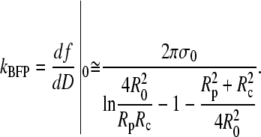
This is an exact expression for the slope of the force-deflection curve f = f(ΔD) at f = 0, which is also the spring constant of the BFP. Using Eq. 29 with  and
and  the BFP spring constant is thus easily calculated from measurable parameters. (Recall that R0 is the radius of the outer cell portion in the force-free state.)
For the sake of comparison with other, approximate results, we may further simplify the above expression provided that the angles  are not too big, which is usually the case. Then, a second-order approximation of Eq. 29 in terms of Rp/R0≪1 and Rc/R0≪1 gives the BFP spring constant as
 |
(30) |
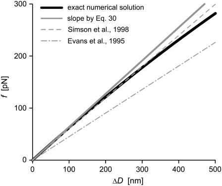
This approximation deviates <0.1% from the exact expression Eq. 29 for typical cell geometries. The “−1” in the denominator is the only surviving contribution in the second-order expansion of the first term inside the square brackets of Eq. 29, whereas the (smaller) quadratic term  results from the expansion of the logarithm. We now see that it is these two terms that are missing in the originally published expression for the spring constant of the BFP (2). Depending on the particular cell geometry, this means that BFP measurements using that spring constant have underestimated the force by 20–40% in the linear force-deflection range. On the other hand, the less used spring constant proposed by Simson et al. (3) does contain the “−1” contribution. However, those authors included higher-order terms in Rp,c/R0 that differ from ours, introducing an error of ∼5–10% in their value of kBFP for typical cell geometries. Fig. 6 combines a numerically modeled force-deflection curve (same as the
  example of Fig. 3 C) with the straight-line approximation defined by Eq. 30 as well as the previously published approximations.
FIGURE 6.
Comparison of a numerically computed force-deflection curve (same example as shown in Fig. 3 C, Δp = 2.5 cm H2O, but with reversed axes) with our linear approximation Eq. 30. Also shown are the results published previously in Evans et al. (2) and Simson et al. (3).
CONCLUSIONS
This study puts forward a comprehensive and rigorous analysis of axial forces produced by pipette-pressurized cells. Its main accomplishments are: i), a flexible numerical treatment to model both pulling and pushing experiments, illuminating nonlinearities in a cell's force-deflection behavior; ii), a prototype of a novel force experiment that relies on this analysis; and iii), a rigorous analytical solution valid at small deformations. In fact, it was the development of a new experimental technique (demonstrated in Fig. 4) that motivated our in-depth theoretical work. The variable contact region between cell and beam surface in such pushing experiments necessitated an analysis that went beyond linear approximations. The excellent agreement of our numerical results with nonlinear experimental data (Fig. 4 B) indeed validated the use of a numerical analysis for this type of experiment. The description of the numerical procedure presented in the first part of this article provides sufficient detail to allow other investigators to reproduce the computational solution with little effort using available numerical libraries (e.g., (18)).
An alternative approach to calculate the force-deflection relation of red blood cells has been described in a thorough and rather complicated work by Simson and co-workers (3). However, their treatment is restricted to BFP-type pulling experiments and cannot be used to analyze the measurements presented in Fig. 4. Their solution proceeds from the assumption that the “shape of the free membrane part is close to a sphere” (an assumption that we only make in the last, analytical part of our treatment when considering nearly spherical shapes), and it involves an intricate series expansion to solve the needed integrals. The resulting nonlinear equation must still be solved numerically to find the sought shape. Remarkably, no discrepancies between the linearized results of this procedure and the originally published BFP spring constant (2,4) were reported.
Our numerical analysis solves the problem at hand exactly and in a much more straightforward and simple manner. Furthermore, it covers any experimental situation that uses pipette-aspirated fluid membranes to exert piconewton forces. The required numerical computations are relatively fast and can thus easily be adopted for the routine interpretation of experimental data. Yet we believe that they are unlikely to completely replace analytical approximations in the near future. Not only have all previous BFP experiments been based on a linearized force-deflection approximation, an analytical solution will also continue to be useful in time-critical applications such as computer-controlled real-time force feedback. In addition, a simplified expression describing asymptotic behavior frequently offers insight into fundamental mechanisms that is not available from numerical analyses.
Having found poor agreement between our exact numerical solution and the previously published BFP spring constant, we proceeded to derive a rigorous analytical approximation for small deflections corresponding to nearly spherical shapes of the free part of the cell. This yielded a simple analytical description of nearly spherical, axisymmetric surfaces of constant mean curvature. Proper treatment of the somewhat cumbersome boundary and auxiliary conditions led eventually to an expression for the slope of the force-deflection curve at vanishing force that is in agreement with our numerical results and replaces the previously published spring constant of the BFP. We emphasize that like our numerical treatment, these analytical derivations are rigorous in the sense that they are exact within their respective orders of approximation. At the same time, their straightforwardness is based on our choice of spherical coordinates—the natural choice when considering perturbations from a sphere. This analytical approach yielded, among others, the highly interesting, practically useful, and easily manageable expressions of Eqs. 23 and 29.
Together, our numerical and analytical analyses furnish the theoretical means to interpret a broad range of biophysical measurements in which piconewton forces are applied using pipette-pressurized membranes as tunable force transducers.
Acknowledgments
This work was in part supported by National Institutes of Health grant R01 A1072391.
APPENDIX: DETAILED ANALYSIS FOR NEARLY SPHERICAL FREE SHAPES
In spherical coordinates (cf. Fig. 5), the cell surface area and volume are
 |
(A1) |
 |
(A2) |
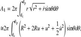
where θc and θp are the θ-boundaries of the free cell part, and A1, V1 denote the area and volume of the free cell portion, respectively. A1 and V1 are calculated as
 |
(A3) |
 |
(A4) |
The far right-hand sides of Eqs. A3 and A4 are second-order expansions in the perturbation u (including derivatives). The axial extension of the free cell part is
 |
(A5) |
We again use the volume constraint  to eliminate the projection length Lp from both the area constraint and the energy. The energy is given by Eq. 5 (main text). Incorporating the surface-area constraint via the Lagrange multiplier σ, and making use of Eq. 12, we arrive at Eq. 22 for the generalized energy functional
  where
where
 |
(A6) |
and
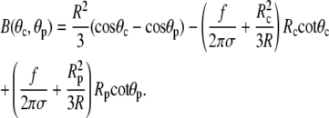 |
(A7) |
Inserting the Lagrange function Eq. A6 into the Euler-Lagrange equation
 |
(A8) |
gives
 |
(A9) |
Substituting t ≡ cosθ, this is recognized as the Legendre differential equation with n = 1. It has the general solution
 |
(A10) |
We fix the position of the origin of our reference frame by requiring that (cf. main text)
 |
(A11) |
This yields C1 = 0 and thus simplifies Eq. A10 to Eq. 23.
Evaluating the boundary condition Eq. 26 using Eqs. A6 and A7 leads to
 |
(A12) |
As explained in the main text, from now on we drop all higher-than-first-order terms of quantities that vanish at f = 0. Thus, the second term in Eq. A12 vanishes. We next replace Rp,c everywhere using Eq. 25. Since f itself is a small quantity, we also drop terms containing fu. Eq. A12 becomes
 |
(A13) |
The derivative of Eq. 23 with respect to θ may be expressed as
 |
(A14) |
Replacing  Eq. A13 simplifies to (cf. Eq. 27)
 |
(A15) |
From Eq. 12, and using 
 |
(A16) |
After multiplying the above equation by f, the term containing fΔR is dropped, and we may rewrite Eq. A15 as
 |
(A17) |
Next, we use the two conditions of Eq. 25 and the area constraint to express ΔR, Δθp, and Δθc in terms of C (and thus of f; cf. Eq. A17). From Eqs. 25 and 23,
 |
(A18) |
For the area constraint we may write
 |
(A19) |
We omit second-order terms in u from the expressions for A1 and V1. From Eq. 23,
 |
(A20) |
After some algebra, Eq. A19 becomes
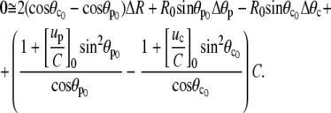 |
(A21) |
Inserting Eqs. A18,
 |
(A22) |
which is easily rearranged to give Eq. 28.
The first-order expansion of Eq. A5 reads
 |
(A23) |
We introduce Eqs. A18, 28, and A17 to obtain
 |
(A24) |
which finally gives the sought slope, Eq. 29.
Editor: Richard E. Waugh.
References
- 1.Evans, E. A., R. Kwok, and T. McCown. 1980. Calibration of beam deflection produced by cellular forces in the 10−9–10−6 gram range. Cell Biophys. 2:99–112. [DOI] [PubMed] [Google Scholar]
- 2.Evans, E., K. Ritchie, and R. Merkel. 1995. Sensitive force technique to probe molecular adhesion and structural linkages at biological interfaces. Biophys. J. 68:2580–2587. [DOI] [PMC free article] [PubMed] [Google Scholar]
- 3.Simson, D. A., F. Ziemann, M. Strigl, and R. Merkel. 1998. Micropipet-based pico force transducer: in depth analysis and experimental verification. Biophys. J. 74:2080–2088. [DOI] [PMC free article] [PubMed] [Google Scholar]
- 4.Merkel, R., P. Nassoy, A. Leung, K. Ritchie, and E. Evans. 1999. Energy landscapes of receptor-ligand bonds explored with dynamic force spectroscopy. Nature. 397:50–53. [DOI] [PubMed] [Google Scholar]
- 5.Evans, E., A. Leung, D. Hammer, and S. Simon. 2001. Chemically distinct transition states govern rapid dissociation of single L-selectin bonds under force. Proc. Natl. Acad. Sci. USA. 98:3784–3789. [DOI] [PMC free article] [PubMed] [Google Scholar]
- 6.Evans, E., A. Leung, V. Heinrich, and C. Zhu. 2004. Mechanical switching and coupling between two dissociation pathways in a P-selectin adhesion bond. Proc. Natl. Acad. Sci. USA. 101:11281–11286. [DOI] [PMC free article] [PubMed] [Google Scholar]
- 7.Perret, E., A. Leung, H. Feracci, and E. Evans. 2004. Trans-bonded pairs of E-cadherin exhibit a remarkable hierarchy of mechanical strengths. Proc. Natl. Acad. Sci. USA. 101:16472–16477. [DOI] [PMC free article] [PubMed] [Google Scholar]
- 8.Evans, E., V. Heinrich, A. Leung, and K. Kinoshita. 2005. Nano- to microscale dynamics of P-selectin detachment from leukocyte interfaces. I. Membrane separation from the cytoskeleton. Biophys. J. 88:2288–2298. [DOI] [PMC free article] [PubMed] [Google Scholar]
- 9.Heinrich, V., A. Leung, and E. Evans. 2005. Nano- to microscale dynamics of P-selectin detachment from leukocyte interfaces. II. Tether flow terminated by P-selectin dissociation from PSGL-1. Biophys. J. 88:2299–2308. [DOI] [PMC free article] [PubMed] [Google Scholar]
- 10.King, M. R., V. Heinrich, E. Evans, and D. A. Hammer. 2005. Nano-to-microscale dynamics of P-selectin detachment from leukocyte interfaces. III. Numerical simulation of tethering under flow. Biophys. J. 88:1676–1683. [DOI] [PMC free article] [PubMed] [Google Scholar]
- 11.Heinrich, V., A. Leung, and E. Evans. 2005. Nano-to-microscale mechanical switches and fuses mediate adhesive contacts between leukocytes and the endothelium. J. Chem. Inf. Model. 45:1482–1490. [DOI] [PubMed] [Google Scholar]
- 12.Heinrich, V., K. Ritchie, N. Mohandas, and E. Evans. 2001. Elastic thickness compressibility of the red cell membrane. Biophys. J. 81:1452–1463. [DOI] [PMC free article] [PubMed] [Google Scholar]
- 13.Pierrat, S., F. Brochard-Wyart, and P. Nassoy. 2004. Enforced detachment of red blood cells adhering to surfaces: statics and dynamics. Biophys. J. 87:2855–2869. [DOI] [PMC free article] [PubMed] [Google Scholar]
- 14.Heinrich, V., and W. Rawicz. 2005. Automated, high-resolution micropipet aspiration reveals new insight into the physical properties of fluid membranes. Langmuir. 21:1962–1971. [DOI] [PubMed] [Google Scholar]
- 15.Elsgolc, L. E. 1961. Calculus of Variations. I. N. Sneddon, M. Stark, and S. Ulam, editors. Pergamon Press, Oxford, UK.
- 16.Katnik, C., and R. Waugh. 1990. Alterations of the apparent area expansivity modulus of red blood cell membrane by electric fields. Biophys. J. 57:877–882. [DOI] [PMC free article] [PubMed] [Google Scholar]
- 17.Heinrich, V., M. Brumen, R. Heinrich, S. Svetina, and B. Zeks. 1992. Nearly spherical vesicle shapes calculated by use of spherical harmonics: axisymmetric and nonaxisymmetric shapes and their stability. J. Phys. J. II. 2:1081–1108. [Google Scholar]
- 18.Press, W. H., S. A. Teukolsky, W. T. Vetterling, and B. P. Flannery. 2002. Numerical Recipes in C++: The Art of Scientific Computing. Cambridge University Press, Cambridge, UK.


