Abstract
To treat acute lung failure, an intravenous membrane gas exchange device, the Hattler Catheter, is currently under development. Several methods were employed to evaluate the biocompatibility of the device during preclinical testing in bovines, and potential coatings for the fibers comprising the device were screened for their effectiveness in reducing thrombus deposition in vitro. Flow cytometric analysis demonstrated that the device had the capacity to activate platelets as evidenced by significant increases in circulating platelet microaggregates and activated platelets. Thrombus was observed on 20 ± 6% of the surface area of devices implanted for up to 53 h. Adding aspirin to the antithrombotic therapy permitted two devices to remain implanted up to 96 h with reduced platelet activation and only 3% of the surface covered with thrombus. The application of heparin‐based coatings significantly reduced thrombus deposition in vitro. The results suggest that with the use of appropriate antithrombotic therapies and surface coatings the Hattler Catheter might successfully provide support for acute lung failure without thrombotic complications.
Keywords: Artificial lung, Biocompatibility, Flow cytometry, Thrombosis, Coatings
Acute respiratory failure may result from a variety of conditions including sepsis, trauma, inhalation injury, and drug overdose (1). Common treatment methods include mechanical ventilation and extracorporeal membrane oxygenation (ECMO). Mechanical ventilation may induce barotrauma, a pulmonary inflammatory response, or even exacerbate existing lung injury and impair remaining healthy lung tissue (1–3). ECMO is associated with increased bleeding and thrombosis (1,4). Additionally, the oxygenator component of the ECMO circuit often requires replacement due to decreased gas exchange related to plasma penetration into fiber pores and/or thrombosis (5). While both mechanical ventilation and ECMO provide effective treatment or many patients, there remains a cohort of individuals for whom these current treatments are not sufficient and a different approach is required.
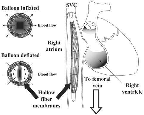
In response to this challenge, a percutaneous intravenous respiratory assist catheter is under development. The device consists of a mat of hollow fiber membranes (HFMs) scrolled around a polyurethane balloon, similar to those employed in intra‐aortic balloon pumping, placed into the vena cava through the femoral or jugular vein.Figure 1 provides a schematic of the device in the superior vena cava‐right atrium‐inferior vena cava (SVC‐RA‐IVC) tract as deployed in the animal studies presented herein. For human use, the device will be inserted in a femoral vein and be placed in the IVC, ideally between the renal veins and the atrium. Carbon dioxide and oxygen are exchanged through the microporous HFMs and the balloon augments mass exchange by reducing the boundary layers around the HFMs. Similar to the intra‐aortic balloon pump, the catheter can be rapidly deployed without the need to enter the operating room or employ general anesthesia. Patient support will be provided by improving oxygen delivery or enhancing carbon dioxide removal in a variety of clinical settings characterized by acute lung failure.
FIG. 1.
The right image (not drawn to scale) shows the catheter within the SVC‐RA‐IVC tract. In the bovine studies the distal end of the catheter resided at about the level of the renal arteries, while the proximal end usually remained in the lower portion of the SVC. The left images display the pulsation of the balloon within the fiber bundle generating radial flow through the fibers.
Previous reports have described the gas exchange properties of the device with different balloon sizes, balloon beat rates, and anatomic positions with studies performed in vitro, ex vivo, and in vivo in both ovines and bovines (6–8). The essential findings demonstrated that balloon pulsation increased gas exchange rates achieved by the device. Increasing the balloon pulsation rate produced higher gas exchange rates in a flow rate dependent manner. That is, the magnitude of the increase in gas exchange resulting from increasing the pulsation rate was highest with lower flows through the device and the amount of change decreased as the flow rate past the device increased.
In this report we have investigated device biocompatibility by applying flow cytometric measures of platelet activation and microaggregate formation as well as postexplant device analysis to 11 catheters implanted in calves for durations of 6–96 h. The purpose of performing these measures was to assess device biocompatibility prior to any surface modification and/or coating, although the overall purpose of each animal implant was focused on defining performance variables of each device, rather than specifically evaluating the blood compatibility of the catheter. After observing some degree of thrombotic deposition in these initial performance evaluation studies, a set of in vitro screening tests were conducted to evaluate several potential HFM coatings.
METHODS
Device insertion and blood collection
All animal studies were conducted in accordance with the University of Pittsburgh Institutional Animal Care and Use Committee approved protocols. The devices were deployed through the jugular vein into the vena cava of 11 juvenile bovines as described previously (6). A bolus of heparin at 4 mg/kg was given intravenously prior to device insertion. The final two animals, which completed the 96‐h protocol, also received 1 g of acetylsalicylic acid dissolved in 500 mL of saline. The device was advanced through the SVC into the RA to the IVC, so that the distal end of the device was in close proximity to the renal veins. Blood samples for platelet assays were collected from the femoral vein and either the central venous pressure line or a line of a Swan‐Ganz catheter (Edwards Lifesciences, Irvine, CA, USA) deployed in the pulmonary artery. Approximately 10 mL of blood was drawn through the line, and then 3 mL of additional blood was collected into a monovette tube containing 3.8% sodium citrate (Sarstedt, Newton, NC, USA) for a final blood to anticoagulant ratio of 9‐1. Samples were collected preoperatively, after insertion of the Swan‐Ganz catheter, but prior to catheter deployment, 2 h after catheter insertion and subsequently at least once daily.
The device consisted of microporous polypropylene HFMs woven into a mat longitudinally and held in place by a nylon weft at right angles to the HMF (x30–240, Celgard Inc., Charlotte, NC, USA). The fiber mat was coiled in approximately six layers around a polyurethane balloon. The total fiber surface area was 0.17 m². Helium, to inflate and deflate the balloon, and the sweep gas were exchanged with a line communicating externally through an incision in the jugular vein. Intravenous heparin was given to maintain an activated clotting time (ACT) of 200–450 s. The target ACT was determined prior to study initiation.
Platelet assays
Circulating activated platelets were quantified with flow cytometric detection of annexin V (BD‐Pharmingen, La Jolla, CA, USA) binding as previously described (9). Circulating platelet microaggregates, small aggregates consisting of a few to several platelets or platelet‐leukocyte microaggregates, were quantified using antibovine CD41/61 (VMRD, Pullman, WA, USA) (10). Samples were analyzed on a FACScan (Becton‐Dickinson, San Diego, CA, USA) flow cytometer.
Postexplant analysis
Immediately prior to study termination, a bolus of heparin was administered along with an overdose of barbiturate and potassium chloride. The lateral chest wall was removed to expose the thoracic organs. The position of the catheter within the vena cava was noted and then the vessel was sliced axially to expose the device. The positioning of the device in relation to the portal and renal veins was recorded. SVC and IVC diameters and lengths to relevant anatomic landmarks were measured. The animal was then exsanguinated by jugular incision (opposite from catheter insertion site). The device was then removed and immediately transferred to a column of saline containing 50 U/mL heparin. A syringe was attached to the balloon luer port and used to inflate and deflate the balloon for about a minute. The heparinized saline was discarded, fresh saline was added, and the balloon was inflated and deflated to rinse again. This process was repeated until the saline remained clear after balloon pulsation.
The intact explanted device was digitally photographed, noting any bending or kinking of the device that would be a result of anatomic variations in the vena caval tract. The front and rear manifolds of the device were then cut off to free the fiber mat, which was cut axially, parallel to the direction of the HFMs and cutting through the weft fibers. The fiber mat was then removed from around the balloon, leaving the fiber mat in stacked sections where each section corresponded to one concentric layer of HFMs. Pieces of the mat (1 cm²) were cut from the proximal, middle, and distal (in relation to the communicating gas delivery line) portions of the mat for scanning electron microscopy (SEM) analysis in 10 of the devices. Individual layers from the remaining mat were then separated and laid out for digital imaging. Any areas of significant gross thrombotic deposition were noted and imaged.
Images of the laid out fiber mat were analyzed with IPLab (Scanalytics, Bethesda, MD, USA). The color image was converted to binary using a color intensity threshold so that areas of thrombotic deposition were converted to black (positive) and the remaining areas changed to white (negative). The percent of the whole mat and individual layer areas positive for deposition was then calculated. This process was repeated on two additional images of the mat and averaged.
Scanning electron microscopy
The pieces previously excised from the mat and a 1‐cm² section of the balloon were prepared for SEM. Individual layers were separated and placed in saline in six well tissue culture plates. Fixation was accomplished by placing samples in 2.5% glutaraldehyde (Taab Laboratories, Berkshire, England) for 60 min at 2–8°C. The samples were rinsed with saline and then placed in 4% osmium tetroxide (Sigma, St. Louis, MO, USA) for 60 min. After rinsing three times with saline, the samples were serially dehydrated by immersion for 10 min in 30, 50, 70, 90, and 100% (the latter three times) ethanol (Sigma). The samples were then placed in an Emscope 450 (Emscope Laboratories, Ashford, UK) for carbon dioxide critical point drying, followed by sputter coating with gold‐palladium. Samples were imaged with a Jeol JEM‐6335F field emission gun scanning electron microscope (Jeol, Peabody, MA, USA).
In vitro thrombus deposition
Three‐centimeter‐diameter circular sections of Celgard (x30–240, Celgard Inc., Charlotte, NC, USA) matted fibers with or without various coatings (described below) were placed individually in 16 × 100 mm siliconized glass tubes (Fisher Scientific, Pittsburgh, PA, USA). Blood was collected from healthy juvenile bovines via jugular venipuncture with an 18‐gauge 1.5‐in. needle (Becton‐Dickinson) into a 600‐mL blood transfer pack (Baxter Healthcare, Deerfield, IL, USA). Heparin was added to the transfer pack prior to blood collection for a final concentration of 0.75 U/mL. The anticoagulation level for these studies was determined by attempting to produce a similar deposition pattern to that observed from device explant studies. Eight milliliters of blood were then added to each glass tube containing a matted fiber section and the tubes were placed on a hematology mixer (Fisher Scientific) for 2 h at 37°C. After this contact period the fiber samples were removed and rinsed in heparinized saline. The percent of the surface covered with thrombus deposition was calculated as described above. All 10 fiber/coating combinations were tested in parallel.
Fiber/coating combinations
Commercial coatings were applied to the matted Celgard fibers, some of which had been previously coated with a thin siloxane membrane (Senko, Medical Instrument Mfg., Tokyo, Japan). The coating combinations investigated are listed in Table 1.
TABLE 1.
Fiber surface treatment/coating combinations
| Coating | Abbreviation | Company |
|---|---|---|
| None | CG | N/A |
| Siloxane | SX | Senko |
| PhotoLink heparin | CG‐H | Surmodics, Eden Prairie, MN |
| SX‐H | ||
| PhotoLink polyvinyl pyrrolidone | CG‐PVP/H | Surmodics |
| X‐coating | CG‐X | Terumo, Tokyo, Japan |
| SX‐X | ||
| Heparin complex T‐2 | CG‐T2 | TUA Systems, Merritt Island, FL |
| Duraflo II | CG‐D | Edwards Lifesciences |
| Bionet | CG‐B | Edwards Lifesciences |
Statistics
Statistical comparisons for the flow cytometric assays were performed using one‐way ANOVA with post hoc Scheffe testing. The percent of surface thrombus deposition for the various coatings was normalized for each experiment by dividing by the percent of surface thrombus deposition on the uncoated Celgard fiber sample, which served as the control, to account for variability in the condition of the blood. The Levene test for homogeneity of the sample variances was performed. The surface deposition results were then compared using one‐way ANOVA using the Welch statistic and post hoc Dunnett’s T3 testing assuming unequal variances. Significance was assumed for P ≤ 0.05. Statistical testing was carried out using SPSS 13 for Windows (SPSS Inc., Chicago, IL, USA).
RESULTS
Table 2 summarizes the 11 bovine implant studies. The gas exchange performance of the catheters in these studies has been previously published (6,7).
TABLE 2.
Summarizes data for the bovine implant studies
| Study no. | Balloon size | Duration | ACT range(s) | Reason for study termination |
|---|---|---|---|---|
| E021 | 40 cc | 4 h | 250–350 | Elective |
| E022 | 40 cc | 6 h | 250–350 | Elective |
| E023 | 40 cc | 6 h | 250–350 | Elective |
| E027 | 40 cc | 6 h | 250–350 | Elective |
| E028 | 40 cc | 6 h | 250–350 | Elective |
| E040 | 25 cc | 27 h | 250–350 | High sweep gas line pressure when animal lay down |
| E041 | 25 cc | 28 h | 350–999 | Diminished gas exchange |
| E043 | 25 cc | 52 h | 300–400 | Diminished gas exchange |
| E044 | 25 cc | 53 h | 250–400 | Diminished gas exchange |
| E052 | 13 cc | 96 h | 200–600 first 24 h, then 200–250 | Elective/end of study |
| E053 | 13 cc | 96 h | 350–450 first 24 h, then 200–300 | Elective/end of study |
Thrombus deposition
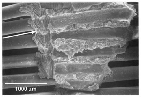
The postexplant analysis revealed that the nylon weft fibers of the fiber mats served as a nidus for thrombus formation. Thrombus was found throughout on the weft fibers and frequently served to attach weft fibers from concentric layers. Occasionally, thrombus would begin to “bridge” two adjacent nylon fibers in the same layer by expanding along the polypropylene fibers as shown in Fig. 2. This was likely to occur where the device was bent by the animal anatomy. Deposition appeared to vary by layer, with the highest amount found on the middle layers and the least found on the inner and outermost layers. However, the difference did not attain statistical significance. It also appeared that deposition was highest in areas where the blood vessel was more tightly constrained, such as adjacent to the liver.
FIG. 2.
The image is an electron micrograph of device HFMs following a 96‐h implant study. A v‐shaped thrombus in the center of the image appears to have formed on the nylon weft fibers of two layers of the fiber bundle. The arrow on the left side of the image indicates an imprint of the weft fibers remaining from where the adjacent fiber layer was peeled away.
The mean surface area of the device with visible thrombus deposition was 20 ± 6% in the nine devices for which the study duration was 53 h or less. In one device, which successfully completed the 96‐h protocol, the deposition was 3% and was exclusively present on the weft fibers. The other device that completed the 96‐h protocol was used for additional gas exchange studies following necropsy, so the percent of surface deposition was not measured.
Scanning electron microscopy
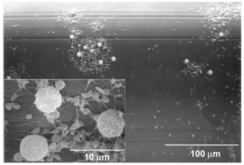
Deposition on the polypropylene fibers varied from patchy areas of adhered activated platelets (as evidenced by extended pseudopodia) on the majority of the HFM surfaces to scattered areas of white thrombus consisting of leukocytes and platelets (Fig. 3). Adherent thrombus was consistently observed on the weft fibers, often with entrapped red blood cells. To some extent, it was difficult to examine the weft fibers, because of thrombus connecting concentric layers of weft fibers, which had to be peeled or cut apart so that individual layers of fiber sections could be observed.
FIG. 3.
A micrograph is shown from the same device as Fig. 2, from an HFM without thrombus visible to the naked eye. The main image shows scattered cellular deposition. The inset shows a higher magnification of the deposition, indicating the composition is primarily platelets and leukocytes. The platelets have extended pseudopodia and some fibrin strands indicating platelet activation.
Flow cytometric studies
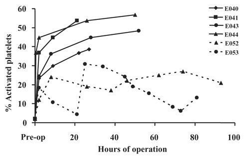
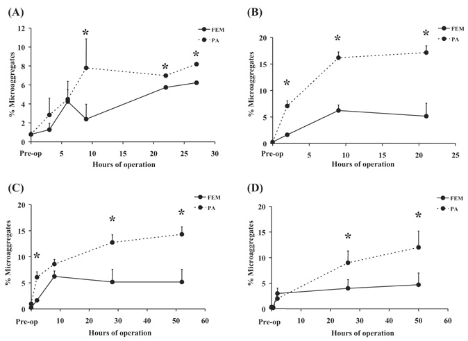
Figure 4 shows that platelet activation, as indicated by annexin V binding to individual activated platelets, was elevated in animals with implant durations in excess of 6 h, but less than 96 h, compared to the two animals which did complete the full 96‐h study duration. In four animals there was a significant (P < 0.05) increase in platelet microaggregates in blood collected distal to the device contact versus blood collected proximal to the device as shown in Fig. 5.
FIG. 4.
The plot shows the percent of circulating activated platelets, as indicated by annexin V binding, versus the time from implant. E040–E053 refers to the study number ( see Table 2). The dashed lines indicate the 96‐h studies, while the solid lines indicate shorter duration studies. All studies display a substantial increase following device insertion that continues to increase with implant duration in the four studies lasting less than 52 h. The two 96‐h studies display a different response, but remain under 32%, a level exceeded by the four shorter studies.
FIG. 5.
The plots show the percent of circulating platelet events which were discriminated as microaggregates by flow cytometry versus the implant duration for (A) E040—a 27‐h study; (B) E041—a 28‐h study; (C) E043—a 52‐h study; and (D) E044—a 52‐h study. The solid line represents blood collected from an access line in the femoral artery (FEM), prior to passing through the device, while the dashed line indicates blood collected from a line placed in the pulmonary artery (PA), after device contact. Data shown are mean + standard deviation. *indicates P < 0.05 for FEM versus PA data.
Fiber/coating combination surface thrombus deposition
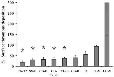
Figure 6 displays the results of the fiber deposition tests normalized to the uncoated Celgard fiber results. The test results indicate the application of heparin coatings significantly reduced thrombus deposition on the fibers in vitro. Application of a siloxane layer to the HFMs alone did not result in a significant decrease in deposition.
FIG. 6.
The chart displays the percent of surface area covered by visible thrombus deposition following rocking a 3‐cm‐diameter swatch of knitted HFMs in bovine blood for 2 h. The description of the coatings appears in Table 1. The data were normalized so that the percent of deposition on the uncoated Celgard fibers equaled 100. Data shown are the means + standard error, except the CG‐X for which the standard error is shown in the negative. *indicates P ≤ 0.05 versus the uncoated Celgard.
DISCUSSION
An intravenous respiratory assist catheter presents a unique biocompatibility challenge. Thus, reflection upon the results from the previous clinical experience with a similar predicate device aids in evaluating the results from these studies. The intravenous oxygenator (IVOX) was an HFM‐based catheter also deployed in the vena cava (11). The principal differences between the IVOX and the device tested herein are the balloon utilized by the current device to generate pulsation, and as a consequence, a smaller HFM surface area (the IVOX was available in four sizes ranging from 0.21 to 0.52 m²) (12). Many of the issues encountered in the developmental studies reported here also occurred during the earlier clinical experiences with the IVOX (11).
While balloon pulsation decreases the required surface area from ∼1 m² in commercial HFM oxygenators and 0.52 m² with the IVOX to 0.17 m², this still represents a significant amount of foreign material in direct contact with the blood. Potential thrombotic deposition on the device is a concern for several reasons. Due to the higher gas exchange rates per unit area of the device, even limited thrombus deposition may adversely impact gas exchange by reducing the effective surface area. Obstruction of flow may increase the pressure drop across the device, limiting venous return, and subsequently reducing cardiac output. Flow obstruction may also result in organ congestion and dysfunction. Vascular obstruction was observed in 5 of the 144 IVOX cases (10). Loosely adherent thrombus or the local formation of microaggregates could result in emboli traveling to the already compromised lungs. Pulmonary embolism was reported in 3 of the 144 cases and necropsies of patients who died during or after IVOX support showed evidence of pulmonary emboli or infarction in 5 of the 68 cases (11). Local activation of platelets and consumption of coagulation factors, coupled with anticoagulation therapy, could lead to bleeding elsewhere in the patient. Indeed, bleeding was the most frequent complication in the IVOX trial and it occurred in 7 of the 11 cases reported. Additionally, 70% of the patients enrolled in the IVOX trial suffered from preexisting hematologic derangements, suggesting the patient population for this therapy is at greater risk for bleeding complications.
Leukocyte interactions with the foreign material of the catheter may result in the release of mediators and cytokines that could lead to a significant inflammatory response. However, the IVOX trial found a nonsignificant decrease in complement factors C3 and C5 following implantation, which may have resulted from reduced ventilator settings and lung recovery (12). Similar measures were not performed in the calves used in this study due to the lack of bovine‐reactive assays.
Failure to maintain the presence of a nonactivated, intact endothelium expressing antithrombotic properties adjacent to the catheter could be an issue contributing to device‐associated thrombosis. During advancement of the catheter, a sheath maintains the device in a compact configuration, and optimistically, prevents damage to or denuding of the endothelial lining of the vessel. Once properly positioned, the sheath can be removed and balloon pulsation initiated. This was similar to the furler used in the deployment of the IVOX. Evidence of abrasion to, inflammation of, or fibrin deposition on the vena cava was found in 10 of the 68 IVOX necropsies (11). There were two cases of visually evident abraded vena caval intima in the calves of our study with associated mural thrombus. Microscopic analysis was not undertaken to examine the presence or absence of a noninflammatory endothelium. Additionally, balloon pulsation can cause flexing of the device resulting in repeated tapping or abrasion of the vessel wall. Hematomas were commonly found on the vessel wall adjacent to the hub of the free end of the catheter.
Device removal also presents a few areas of concern. Deflation of the balloon will allow the device to collapse during extraction; however, the concerns of exit site bleeding, femoral vein abrasion and tearing persist. Thrombus present on the device may be dislodged during removal, producing emboli. During in vivo studies, even with thrombus present on over 20% of the catheter area, thrombus was well adhered and presented a low profile relative to the fibers, so that embolization appeared unlikely. The primary purpose of removing the device by isolation and incision of the vena cava was to document the device location in relation to anatomical landmarks. This method also allowed observation of the device appearance without the potential artifacts associated with device removal.
It should be emphasized that biocompatibility was not the primary focus for these animal implant studies. The specific goals of individual studies varied, but the principal objectives were to measure the effects of balloon pulsation rates and balloon size on gas exchange rates and cardiac output, as well as to improve the ease of insertion, among other objectives.
Future studies will involve application of a micron thick siloxane coating on the fibers to prevent plasma penetration into hollow fiber pores without adversely impacting mass exchange rates (13). A bioactive heparin coating might also be deposited on top of the siloxane layer. A functional heparin coating would be desirable to potentially reduce the demand for systemic anticoagulation in addition to maintaining adequate anticoagulant activity at the site of need (5).
There was some degree of thrombotic deposition on all of the devices tested in vivo. The flow cytometry data clearly indicate that deployment and operation of the device caused platelet activation and microaggregate formation. The implants with durations of 53 h or less used only heparin anticoagulation, while the longer studies were performed with extended ACTs plus the administration of acetylsalicylic acid to achieve the desired 96‐h end point with minimal deposition. The difference in the antithrombotic strategy may account for the differences in the levels of platelet activation observed with the shorter (less than 53 h) versus longer (96 h) duration implants. While this level of anticoagulation may be sustainable in the clinical setting for brief durations, it would likely produce a significant bleeding risk for the duration of intended support (up to two weeks) and is probably not reasonable. This finding demonstrates the need to reduce the thrombogenicity of the device so that the patient systemic hemostatic activity can be maintained at a clinically acceptable level.
The pattern of deposition on the catheter also raises some concern. Thrombus was always present on the weft fibers that constrain the hollow fiber bundle. For the most part the weft fibers were aligned adjacent to each other as the bundle was scrolled. Thus, the thrombus from adjacent weft fibers adhered to each other. During postnecropsy examination of the devices, the layers had to be peeled apart with some force due to thrombus adhesion between adjacent layers. If these focal adhesions were present on the device in vivo, they would form an obstruction to axial blood flow through the fiber bundle. For the most part, there was little deposition on the HFMs, so that fluid could still pass around them. This pattern would create channels in the fiber bundle which would allow radial flow through the bundle, but restrict axial flow to the areas closest to the balloon and nearest to the vessel wall.
Clinically, the rate of thrombus accumulation on the IVOX during the first 4 days after implant was 3.3 g/24 h. However, this device did not utilize the weft fibers which were the nidus for thrombus deposition on the device used in these animal studies (14). Instead, deposition was most common at the hubs in the IVOX, where the fibers were potted together. Deposition was relatively minor or absent in the current device in these same areas. Thus, the pattern of deposition on the two devices does not appear to be similar. The IVOX hollow fibers were also coated with an ultrathin silicone layer to prevent plasma penetration into the fiber pores. A similar treatment is planned for the clinical version of the current catheter, but was not implemented for these animal studies.
The flow cytometry assays indicated clear evidence of platelet activation, but at levels less than previously observed with ventricular assist devices, which have subsequently been successfully used clinically (8). The platelet assays also appeared to be related to the overall degree of deposition based on observation at device explant.
The rocker plate blood contacting tests with hollow fiber membrane sections provided a simple, repeatable method to rapidly screen coatings and surface treatments. Altering the amount of heparin used can modify the severity of the tests. This inherent flexibility could be used to differentiate between two relatively biocompatible materials. The tests demonstrated that applying a heparin‐based coating to the fiber section, both HFMs and weft fibers, reduced deposition, while application of siloxane to only the HFMs did not produce a significant reduction. The nylon weft fibers may provide more reactive groups (especially amide groups) to aid in the application of a coating compared to polypropylene or siloxane, which may explain the observed differences in thrombus deposition.
Overall, this study demonstrated a multimodal method for assessing biocompatibility in preclinical testing of cardiovascular devices. Subsequent to identifying the locus of thrombus formation, a set of simple tests was performed to identify treatments which may be suitable for reducing the deposition observed in the in vivo studies. The flow cytometric assays and surface deposition methods may be repeated in studies of the device following application of a coating to assess biocompatibility improvement.
Acknowledgements
The authors would like to acknowledge the staff of the Experimental Surgery Program at the University of Pittsburgh and Lisa Gordon in particular for her assistance in sample collection. Funding has been provided by the Department of Defense, National Institutes of Health, McGowan Institute for Regenerative Medicine, and the Commonwealth of Pennsylvania.
The work presented in this publication was made possible, in part, by Grant Number HL70051 from the National Institutes of Health (NIH), National Heart, Lung, and Blood Institute and its contents are solely the responsibility of the authors and do not necessarily represent the official views of the National Heart, Lung, and Blood Institute or NIH.
REFERENCES
- 1.Kahdi FU, Childs E, Touijer K. Acute respiratory distress syndrome. Am Fam Physician. 2003;63:315–322. [PubMed] [Google Scholar]
- 2.Anzueto A, Frutos‐Vivar F, Esteban A, et al. Incidence, risk factors and outcome of barotraumas in mechanically ventilated patients. Intensive Care Med. 2004;134:2187–2194. doi: 10.1007/s00134-004-2187-7. [DOI] [PubMed] [Google Scholar]
- 3.Adams AB, Simonson DA, Dries DJ. Ventilator‐induced lung injury. Respir Care Clin N Am. 2003;9:343–362. doi: 10.1016/s1078-5337(03)00042-x. [DOI] [PubMed] [Google Scholar]
- 4.Mols G, Loop T, Geiger K, Farthman E, Benzing A. Extra‐corporeal membrane oxygenation. A ten‐year experience. Am J Surg. 2000;180:144–154. doi: 10.1016/s0002-9610(00)00432-3. [DOI] [PubMed] [Google Scholar]
- 5.von Segesser LK. Cardiopulmonary support and extracorporeal membrane oxygenation for cardiac assist. Ann Thorac Surg. 1999;68:672–677. doi: 10.1016/s0003-4975(99)00543-3. [DOI] [PubMed] [Google Scholar]
- 6.Hattler BG, Lund LW, Golob J, et al. A respiratory gas exchange catheter: in vitro and in vivo tests in large animals. J Thorac Cardiovasc Surg. 2002;124:520–530. doi: 10.1067/mtc.2002.123811. [DOI] [PubMed] [Google Scholar]
- 7.Eash HJ, Frankowski BJ, Litwak K, Wagner WR, Hattler BG, Federspiel WJ. Acute in vivo testing of a respiratory assist catheter: implants in calves versus sheep. ASAIO J. 2003;49:370–377. doi: 10.1097/01.MAT.0000074991.94234.B6. [DOI] [PMC free article] [PubMed] [Google Scholar]
- 8.Eash HJ, Frankowski BJ, Hattler BG, Federspiel WJ. Evaluation of local gas exchange in a pulsating respiratory support catheter. ASAIO J. 2005;52:152–157. doi: 10.1097/01.MAT.0000153648.11692.D0. [DOI] [PMC free article] [PubMed] [Google Scholar]
- 9.Snyder TA, Watach MJ, Litwak KN, Wagner WR. Platelet activation, aggregation, and life span in calves implanted with axial flow ventricular assist devices. Ann Thorac Surg. 2002;73:1993–1998. doi: 10.1016/s0003-4975(02)03549-x. [DOI] [PubMed] [Google Scholar]
- 10.Baker LC, Davis WC, Auteri J. Flow cytometric assays to detect platelet activation and aggregation in device‐implanted calves. J Biomed Mater Res. 1998;41:312–321. doi: 10.1002/(sici)1097-4636(199808)41:2<312::aid-jbm17>3.0.co;2-m. [DOI] [PubMed] [Google Scholar]
- 11.Conrad SA, Bagley A, Bagley B, et al. Major findings from the clinical trials of the Intravascular Oxygenator. Artif Organs. 1994;18:846–863. doi: 10.1111/j.1525-1594.1994.tb03334.x. [DOI] [PubMed] [Google Scholar]
- 12.Conrad SA, Eggerstedt JM, Grier LR, Morris VF, Romero MD. Intravenacaval membrane oxygenation and carbon dioxide removal in severe acute respiratory failure. Chest. 1995;107:1689–1697. doi: 10.1378/chest.107.6.1689. [DOI] [PubMed] [Google Scholar]
- 13.Eash HJ, Jones HM, Hattler BG, Federspiel WJ. Evaluation of plasma resistant hollow fiber membranes for artificial lungs. ASAIO J. 2004;50:491–497. doi: 10.1097/01.mat.0000138078.04558.fe. [DOI] [PubMed] [Google Scholar]
- 14.Imai H, Schaap RN, Mortensen JD. Rate of thrombus accumulation on intravenacaval IVOX devices explanted from human clinical trial patients with acute respiratory failure. Artif Organs. 1994;18:818–821. doi: 10.1111/j.1525-1594.1994.tb03329.x. [DOI] [PubMed] [Google Scholar]


