

Abstract
Objective
The purpose of this study was to identify the pressure threshold for the destruction of Optison (octafluoropropane contrast agent; Amersham Health, Princeton, NJ) using a laboratory-assembled 3.5-MHz pulsed ultrasound system and a clinical diagnostic ultrasound scanner.
Methods
A 3.5-MHz focused transducer and a linear array with a center frequency of 6.9 MHz were positioned confocally and at 90° to each other in a tank of deionized water. Suspensions of Optison (5–8 × 10⁴ microbubbles/mL) were insonated with 2-cycle pulses from the 3.5-MHz transducer (peak rarefactional pressure, or Pr, from 0.0, or inactive, to 0.6 MPa) while being interrogated with fundamental B-mode imaging pulses (mechanical index, or MI, = 0.04). Scattering received by the 3.5-MHz transducer or the linear array was quantified as mean backscattered intensity or mean digital intensity, respectively, and fit with exponential decay functions (Ae−kt + N, where A + N was the amplitude at time 0; N, background echogenicity; and k, decay constant). By analyzing the decay constants statistically, a pressure threshold for Optison destruction due to acoustically driven diffusion was identified.
Results
The decay constants determined from quantified 3.5-MHz radio frequency data and B-mode images were in good agreement. The peak rarefactional pressure threshold for Optison destruction due to acoustically driven diffusion at 3.5 MHz was 0.15 MPa (MI = 0.08). Furthermore, the rate of Optison destruction increased with increasing 3.5-MHz exposure pressure output.
Conclusions
Optison destruction was quantified with a laboratory-assembled 3.5-MHz ultrasound system and a clinical diagnostic ultrasound scanner. The pressure threshold for acoustically driven diffusion was identified, and 3 distinct mechanisms of ultrasound contrast agent destruction were observed with acoustic techniques.
Keywords: acoustically driven diffusion, Optison, rapid fragmentation, static diffusion, ultrasound contrast agent destruction
Diagnostic ultrasound, combined with the injection of ultrasound contrast agents (UCAs) into the vasculature, provides the practitioner with an estimate of blood velocity and fractional blood volume in the myocardium,1 the kidney,2 and the brain.3 Ultrasound imaging has shown promise for non-invasive quantification of tissue blood perfusion. The technique, known as perfusion imaging, takes advantage of the response of UCAs to low- and high-output acoustic pulses. The accuracy of this technique depends on complete and rapid loss of the contrast enhancement on high-power insonation and negligible microbubble destruction during the imaging phase. Rapid destruction of a UCA is possible through a process known as fragmentation, and pressure thresholds for fragmentation of several UCAs have been identified.4,5 A substantial loss of echogenicity is also possible at acoustic pressures lower than the fragmentation threshold. This type of destruction is caused by acoustically driven gas diffusion through defects in the shell that stabilizes the encapsulated bubble against rapid dissolution.6,7 However, the different pressure thresholds for these mechanisms of destruction have yet to be carefully identified for Optison (octafluoropropane [OFP] contrast agent; Amersham Health, Princeton, NJ). The objectives of this study were (1) to establish criteria for identifying the destruction of a UCA acoustically, (2) to identify the pressure threshold for Optison destruction using these criteria with a laboratory-assembled system and a clinical diagnostic ultrasound scanner (HDI 5000; Philips Medical Systems, Bothell, WA), and (3) to compare the destruction thresholds identified with these 2 techniques.
Materials and Methods
Transducer Calibration
All calibration measurements were made in a 36 × 24 × 20-in acrylic tank filled with deionized water. A motorized 3-axis translation system (NF90 series; Velmex, Inc, Bloomfield, NY) provided 0.02-mm precision for moving calibration hydrophones throughout the transmitted acoustic fields. Measurements made with the hydrophones were digitized with an oscilloscope (Waverunner DSO; LeCroy Corporation, Chestnut Ridge, NY) and transferred to a desktop computer (Power Macintosh 8100; Apple Computer, Inc, Cupertino, CA). The calibration system was automated and controlled with a collection of visual interface programs written in LabVIEW (National Instruments Corporation, Austin, TX) on the desktop computer.
Destructive pulses were delivered with a 3.5-MHz single-element focused transducer (Picker model 595831A). This frequency is commonly used in cardiac applications of diagnostic ultrasound, and Optison has been approved by the US Food and Drug Administration for clinical use in the heart. The transducer was driven with single-cycle sinusoidal excitation pulses generated with an Agilent 33250A waveform generator (Agilent Technologies, Palo Alto, CA), amplified by 40 dB with an Amplifier Research 150LA amplifier (AR Worldwide, Souderton, PA), and routed to the transducer via a laboratory-constructed transmit/receive circuit.8 A 0.2-mm needle hydrophone (Precision Acoustics Ltd, Dorchester, England) was used to map the spatial distribution of the transmitted pressure pulses. The output of the transducer was a 2-cycle pulse with a center frequency (fc) of 3.5 MHz and a −6-dB bandwidth of 1.7 MHz. The focal length (60 mm) and −3-dB beamwidth (1 mm) were determined from the beam profiles plotted in the axial and transverse planes. A 15-μm-thick polyvinylidene difluoride bilaminar membrane hydrophone with a 0.4-mm-diameter active element (Precision Acoustics Ltd) was used to calibrate the absolute pressure output at the focus of the 3.5-MHz transducer as a function of the input voltage.
Contrast agent destruction was monitored by a Philips HDI 5000 system using an L12-5 imaging probe. The output of the L12-5 imaging probe was characterized experimentally with the 0.4-mm polyvinylidene difluoride bilaminar membrane hydrophone. In B-mode, the probe transmits multiple single-cycle pulses with an fc of 6.9 MHz. This frequency is considerably greater than the resonance frequency of Optison and, therefore, can be used to monitor the response of Optison to 3.5-MHz pulses with minimal contribution to bubble oscillations. Pressure measurements were also made to confirm that the on-screen mechanical index (MI) and the derated peak rarefactional pressure (Pr) were related by fc−1/2.9
For experiments, the Philips HDI 5000 diagnostic ultrasound scanner was operated in 2 image acquisition modes. The selection of image acquisition mode depended on the duration of ultrasound exposure. For relatively short exposure times (<2 seconds), B-mode images were acquired in a video format and saved directly to a magneto-optical disk using the Philips ResearchLink software. For longer exposure times, freeze-captured gray scale images (JPEG format) were saved directly to a CD. Although the pixel brightness within a region of interest (ROI) in images acquired in the video format (quantified as mean digital intensity) was directly proportional to backscattered acoustic power, the relationship between pixel brightness within an ROI in images in the JPEG format (quantified as mean gray scale value [MGSV]) and backscattered acoustic power was unknown. Therefore, MGSV was converted to mean digital intensity in all Optison destruction experiments. The relationship between MGSV and mean digital intensity was elucidated by analyzing B-mode images of a tissue-mimicking phantom that were saved in JPEG and video formats. The L12-5 linear array was coupled to the phantom (Multipurpose Phantom; ATS Laboratories, Inc, Bridgeport, CT) with ultrasound transmission coupling gel (Aquasonic 100; Parker Laboratories, Inc, Fairfield, NJ) and operated at an MI of 0.32. The persistence was deactivated, and gray scale map 1 was chosen for calibration and subsequent experiments. The gain settings on the scanner (2-dimensional [2D] and time-gain compensation [TGC]) were adjusted so that the entire range of gray scale values (0–255) appeared in the image (Figure 1). A B-mode image of the phantom and its gray scale map were freeze captured and transferred to a desktop computer (Dimension 4600; Dell Inc, Austin, TX). Without changing the phantom setup or the HDI 5000 settings, a video clip was acquired and saved directly to a magneto-optical disk using the Philips ResearchLink software. The MGSV within a 5 × 5-mm ROI of the freeze-captured image was quantified with NIH Image J software (National Institutes of Health, Bethesda, MD). The images in the video format were analyzed with the same ROI to quantify mean digital intensity with Philips QLab software. The ROI was moved in 5-mm increments from the top to the bottom of the acquired phantom image, and the MGSV and mean digital intensity were noted for each ROI. The mean digital intensity was plotted against MGSV, and a quadratic least squares fit to the data was performed (Figure 2). The resulting equation (y = −0.0014x2 + 0.5489x; r2 = 0.999) was used in subsequent experiments to convert MGSV to digital intensity.
Figure 1.
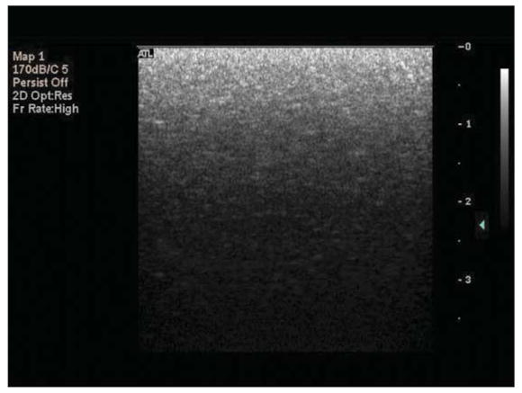
Freeze-captured B-mode image of the tissue phantom. The gain settings on the Philips HDI 5000 system (2D and TGC) were adjusted so that the entire range of gray scale values (0–255) appears in the image (bottom to top).
Figure 2.
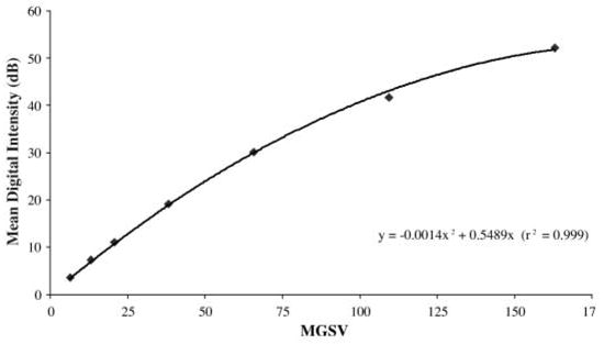
Relationship between MGSV and mean digital intensity for the Philips HDI 5000 diagnostic ultrasound scanner. The L12-5 imaging probe was operated at an MI of 0.32; the persistence was deactivated; and gray scale map 1 was chosen.
Sample Preparation and Positioning
The experimental apparatus for this study is shown in Figure 3. The focused transducer and imaging probe were aligned orthogonally and confocally in the 36 × 24 × 20-in acrylic tank filled with deionized water. Sample suspensions were made by gently mixing freshly drawn Optison (using a secondary vent to prevent agent rupture) with phosphate-buffered saline (PBS) to a final volumetric ratio of 0.1 mL/1 L (Optison concentration = 5–8 × 10⁴ microbubbles/mL). An acoustically transparent sample holder was assembled by pulling a latex condom over a cylindrical polyvinyl chloride frame. The acoustic properties of latex (ρ ≈ 0.91 × 10⁻³ kg/m3; c ≈ 1600 m/s) are similar to those of water, so that approximately 90% of the free-field acoustic intensity is effectively transmitted to the sample.10 The sample chamber was filled with 15 mL of a fresh Optison suspension and positioned with a stainless steel rod attached to the computer-controlled, motorized 3-axis translation system. The sample chamber was oriented so that the Optison sample was within the overlapping foci of the 2 transducers. Before driving the transducers, each Optison suspension was allowed to stabilize for 20 to 30 seconds to minimize variations in the acquired images and radio frequency (RF) traces due to convection of microbubbles through the exposure volume.
Figure 3.
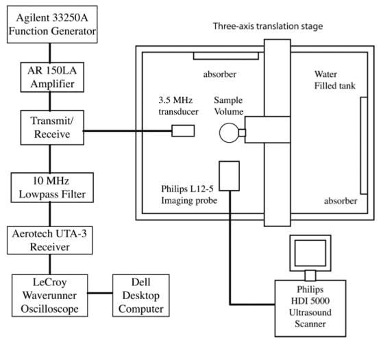
Experimental apparatus for Optison destruction studies.
Experimental Procedure
Stability of Optison
The diffusion rate of encapsulated OFP into PBS at room temperature (20°C) was assessed with the Philips HDI 5000 system without exposure to 3.5-MHz ultrasound. The exposure and acquisition settings on the HDI 5000 system are shown in Table 1. For assessment of the diffusion rate of OFP in static PBS saturated with air, Optison suspensions were left unperturbed (both transducers were inactive) in PBS for 5 minutes. The L12-5 probe was activated only at 0, 120, and 300 seconds after each suspension was properly positioned in the tank to capture B-mode images of the sample. The images were transferred to a desktop computer (Dell Dimension) for image analysis with NIH Image J software. The gray scale values for each image were converted to digital intensity by the quadratic function determined experimentally during calibration. The mean digital intensity was determined for an ROI within the sample volume equivalent to the 3.5-MHz transducer focal area (7 mm2) and plotted against time.
Table 1.
Settings Used for the Diagnostic Ultrasound Scanner
| Parameter | Specification/Setting |
|---|---|
| Machine type | Philips HDI 5000 with L12-5 imaging probe |
| MI | 0.04 (as read on screen) |
| Frequency, MHz | 6.9 |
| Frame rate, frames/s | 14 |
| PRF | 2D PRF, low (5.5 kHz) |
| TGC curve | Positioned at center |
| Gain | Preset* |
| Gray map | 1 (most linear) |
| Depth, cm | 3.9 |
| Focus position, cm | 2.3 |
| Persistence | Off |
| Mode | Fundamental B-mode |
The HDI 5000 system has no quantitative indicator of gain settings. A tissue-specific preset from the Small Parts menu was used for all experiments.
For identification of the pressure threshold for acoustically driven diffusion at 3.5 MHz, the L12-5 probe transmitted pulses continuously to image the treatment volume. To ensure that the continuous B-mode imaging protocol did not contribute to the overall diffusion, the effect of constant exposure with low-MI imaging pulses on the diffusion rate of encapsulated OFP in static PBS was also studied. With the use of the exposure and acquisition settings listed in Table 1, Optison suspensions were exposed to B-mode image pulses continuously for 5 minutes while the 3.5-MHz transducer was inactive. A total of 49 images were acquired (1 every 5 seconds for the first 3 minutes, followed by 1 every 10 seconds for the next 2 minutes) and transferred to the desktop computer for image analysis. After the gray scale values were converted to digital intensity, the mean digital intensity within a rectangular ROI (7 mm2) was calculated and plotted against time. The loss of echogenicity due to diffusion of OFP during continuous B-mode imaging was compared with the data acquired at time 0 and at 120 and 300 seconds.
To quantify the diffusion rates, a least squares fit of the data to an exponential decay function of the form Ae−kt + N was performed, where A + N was the amplitude at time 0; N was the background echogenicity, or noise in the image data; and k was the decay constant. Images were analyzed for both intermittent and continuous B-mode imaging. The decay constant (kB-mode) was noted for each ultrasound exposure scheme.
Acoustically Driven Diffusion
Experiments were conducted to (1) identify the pressure threshold for acoustically driven diffusion and (2) assess the behavior of Optison under prolonged exposure to acoustic pressure amplitudes below and above the destruction threshold. Optison suspensions were insonated with pulses from the 3.5-MHz transducer and L12-5 imaging probe simultaneously. The output of the L12-5 imaging probe was kept low (MI = 0.04) to ensure that the loss of Optison echogenicity was due primarily to destructive pulses from the 3.5-MHz transducer.
The 3.5-MHz transducer transmitted 2-cycle pulses with a Pr varying from 0.0 (inactive) to 0.5 MPa for threshold studies and varying from 0.0 to 0.2 MPa for prolonged exposure studies. The pulse repetition frequency (PRF) was 100 Hz for all experiments. The drive and receive electronics for the 3.5-MHz focused transducer were connected to the transducer through a transmit/receive circuit. The received signal was filtered by a 10-MHz low-pass filter and amplified by an Aerotech UTA-3 pulser/receiver (KB Aerotech, Stratford, CT) and a booster amplifier (Precision Acoustics Ltd) (Figure 3). The total amplification provided by the electronics was approximately 60 dB. The amplified signals were digitized (sampling frequency, 100 MHz) and displayed on a LeCroy Waverunner DSO oscilloscope, which was operated in the sequence mode. A total of 16 traces were acquired for threshold studies (1 trace every 71.5 milliseconds), whereas 24 traces were acquired for prolonged exposure studies (1 trace every 5 seconds).
The intensity of the RF traces, which was proportional to the backscattered acoustic power received by the focused transducer, was quantified by calculating the mean squared voltage. This value, denoted the backscattered intensity (BSI), represented the spatial average of the acoustic power backscattered within the exposure volume. The BSI was computed at each acquisition time point, averaged across samples (n ≥ 6), and plotted as a function of time. As before, exponential decay functions of the form Ae−kt + N were fit to the data, and the decay constants (kRF) were noted. The plots were normalized to the BSI at time 0 (A + N) to allow for comparison of the decay rates as a function of applied pressure. A typical plot of normalized BSI versus time and associated RF traces is shown in Figure 4A.
Figure 4.
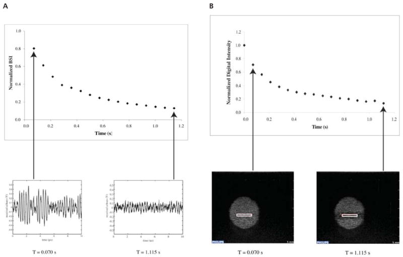
Representative examples of the correlation between acquired RF traces and normalized BSI (A) and echogenicity from an ROI within acquired B-mode images and normalized digital intensity (B). The RF traces and B-mode images were captured simultaneously while Optison was insonated with 3.5-MHz pulses with a Pr of 0.5 MPa (MI = 0.28).
The settings on the HDI 5000 system for image acquisition are given in Table 1. For threshold studies, a total of 17 B-mode images were acquired on the HDI 5000 diagnostic ultrasound scanner in the video format (frame rate, 14 Hz) using the Philips ResearchLink software. For the prolonged exposure study, a total of 25 B-mode images were acquired by the freeze capture technique (1 image every 5 seconds).
An example of Optison destruction captured with B-mode imaging is shown in Video 1. Image analysis of the recorded videos was performed with Philips QLab software. The mean digital intensity was determined within a 7-mm2 ROI for each frame, averaged across samples, and plotted against time. An exponential decay function of the form Ae−kt + N was fit to the data, and the decay constant (kB-mode) was noted for each exposure. The plots were normalized to the mean digital intensity at time 0 to allow for comparison of the decay rates resulting from various applied pressures. A typical plot of normalized mean digital intensity versus time and the associated B-mode images is shown in Figure 4B.
For the B-mode images acquired with the freeze capture technique, the gray scale values were converted to digital intensity. The mean digital intensity within a 7-mm2 ROI was determined for each image, averaged across samples, and plotted against time. As before, an exponential decay function of the form Ae−kt + N was fit to the data, and the decay constant (kB-mode) was recorded. The data were normalized with respect to the value calculated at time 0 to allow for comparison between applied pressures.
Statistical Analysis
To determine the pressure threshold for acoustically driven diffusion, statistical analysis was performed on RF and B-mode image data acquired with different acoustic pressure amplitudes. Each RF or B-mode data set was subtracted from the least squares fit for echogenicity data taken for the next lowest exposure amplitude. A 2-sample, unequal-variance Student t test was performed on these calculated difference sets for adjacent acoustic exposure outputs. The pressure threshold for acoustically driven diffusion was defined as the first Pr that resulted in a data set that was significantly different statistically from the experimental run with a lower acoustic pressure amplitude (P < .05).
Results
Stability of Optison
The stability of Optison suspensions with or without insonation is shown in Figure 5. Optison not exposed to pulsed ultrasound lost 56% of its echogenicity after 2 minutes on average and 96% after 5 minutes. The data show that the denatured albumin shell is permeable to OFP. For Optison suspensions continuously exposed to B-mode imaging pulses, the loss of echogenicity was negligible for the first 90 seconds, followed by an exponential decay (kB-mode = 0.01 s−1; r2 = 0.99) for the remaining 210 seconds. This type of behavior has been reported previously in a study on the stability of Quantison and Myomap (Quadrant Healthcare, Ltd, Nottingham, England).11 The data in Figure 5 show that continuously exposing Optison with low-MI B-mode imaging pulses does not significantly change the diffusion rate of OFP into the surrounding medium.
Figure 5.
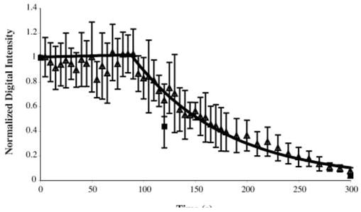
Loss of echogenicity from Optison suspensions sitting unperturbed (■) or during continuous B-mode imaging (Δ).
Acoustically Driven Diffusion
The rate of Optison destruction for a range of Pr outputs from the 3.5-MHz transducer is shown in Figure 6. The decay constants from the fit of the echogenicity data for each exposure to exponential functions are listed in Table 2. Optison destruction at very low incident pressures (Pr ≤ 0.13 MPa) was negligible but not 0 because of static diffusion. At such low incident pressures, the associated decay constants were much less than 1 (Table 2). Evidence of acoustically driven diffusion was detected first at a Pr amplitude of 0.15 MPa. The decay constants for this exposure output (kRF = 1.50; kB-mode = 1.50) were significantly greater statistically than the decay constants at a Pr of 0.13 MPa (P ≪ .05). Therefore, the Pr threshold for acoustically driven diffusion of Optison was 0.15 MPa (MI = 0.08) at 3.5 MHz. Optison destruction occurred more rapidly as the Pr amplitude increased to 0.4 MPa (MI = ≥0.4 MPa; 0.21). At higher incident pressures (Pr MI ≥ 0.21), Optison echogenicity diminished to background levels in less than 1 second. In this case, Optison destruction was most likely the result of shell fragmentation and bubble liberation. The temporal behavior of the normalized mean digital intensity and BSI showed similar trends in decay rates, and the respective decay constants were equivalent (Table 2). These results show that both acquisition and processing techniques were sufficient for identifying the pressure threshold for acoustically driven diffusion or rapid fragmentation. In addition, these 2 distinct types of Optison destruction can be differentiated.
Figure 6.
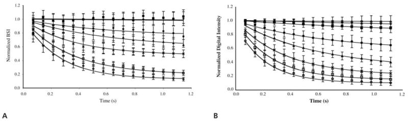
Normalized BSI (A) and normalized digital intensity (B) as a function of time for short-term exposure to Pr values of 0.1 (◆), 0.13 (■), 0.15 (●), 0.2 (▲), 0.3 (×), 0.4 (□), and 0.5 (○) MPa. Note that B also contains sham exposure data (Δ, 0.0 MPa).
Table 2.
Decay Constants Characterizing Data Quantified From RF Traces (kRF) and B-Mode Images (kB-mode) for Short-term Exposures (≈1 Second)
| Peak Negative Pressure, MPa | MI | kRF, s−1 | kB-mode, s−1 |
|---|---|---|---|
| 0.00 | 0.00 | NA | 0.01 (r2 = 0.61) |
| 0.10 | 0.05 | 0.08 (r2 = 0.41) | 0.10 (r2 = 0.98) |
| 0.13 | 0.07 | 0.10 (r2 = 0.20) | 0.80 (r2 = 0.98) |
| 0.15 | 0.08 | 1.50 (r2 = 0.90) | 1.50 (r2 = 1.00) |
| 0.20 | 0.11 | 1.60 (r2 = 0.95) | 1.75 (r2 = 1.00) |
| 0.30 | 0.16 | 2.80 (r2 = 0.97) | 2.80 (r2 = 1.00) |
| 0.40 | 0.21 | 3.00 (r2 = 1.00) | 3.90 (r2 = 1.00) |
| 0.50 | 0.28 | 4.00 (r2 = 0.99) | 4.60 (r2 = 1.00) |
The pressure threshold for acoustically driven diffusion at 3.5 MHz was a Pr of 0.15 MPa (MI = 0.08). NA indicates not applicable.
The relationship between acoustically driven diffusion and time is illustrated in Figure 7. The rate of Optison destruction became more rapid for exposures at and above the threshold for acoustically driven diffusion. For example, suspensions insonated with a Pr of 0.2 MPa retained approximately 50% of the initial echogenicity after 10 seconds of exposure but retained only 10% after 115 seconds. The loss of echogenicity was not as severe for exposure levels below the threshold for acoustically driven diffusion. Suspensions insonated with a Pr of 0.1 MPa still retained approximately 50% of their initial echogenicity after 115 seconds of exposure.
Figure 7.
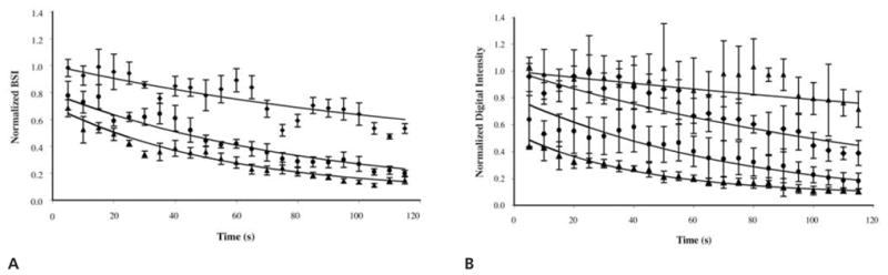
Normalized BSI (A) and normalized digital intensity (B) as a function of time for prolonged exposure to Pr values of 0.1 (◆), 0.15 (●), and 0.2 (▲) MPa. Note that B includes sham exposure data (Δ, 0.0 MPa).
The decay constants for prolonged exposure of Optison (≈120 seconds) are given in Table 3. The decay constants for these longer exposure times were much less than the decay constants for short exposures (≈1 second). Our data show that Optison destruction is rapid initially and becomes more gradual over longer exposure periods.
Table 3.
Decay Constants Characterizing Data Quantified From RF Traces (kRF) and B-Mode Images (kB-mode) for Prolonged Exposures (≈120 Seconds)
| Peak Negative Pressure, MPa | MI | kRF, s−1 | kB-mode, s−1 |
|---|---|---|---|
| 0.00 | 0.00 | NA | 0.00 (r2 = 0.58) |
| 0.10 | 0.05 | 0.01 (r2 = 0.79) | 0.01 (r2 = 0.92) |
| 0.15 | 0.08 | 0.01 (r2 = 0.96) | 0.01 (r2 = 0.92) |
| 0.20 | 0.11 | 0.02 (r2 = 0.96) | 0.02 (r2 = 0.88) |
NA indicates not applicable.
Discussion
Ultrasound contrast agents have the potential to improve the signal-to-noise ratio in ultrasound images and to expand the utility of diagnostic ultrasound to include assessment of tissue blood perfusion. Because most sonographic techniques for perfusion imaging involve the destruction and replenishment of UCAs in the exposure volume, there is an increased need to understand UCA destruction qualitatively and quantitatively. Other researchers have used optical and acoustic techniques to identify 3 dominant mechanisms of Optison destruction: static diffusion, acoustically driven diffusion, and fragmentation.4,6,7 The fragmentation threshold has been identified for a number of UCAs at various frequencies.4,5 However, the threshold for the slow diffusion process has not yet been identified. To define a threshold, one must identify processes that are unique to that event and that can be quantified. Acoustically driven diffusion is more subtle than fragmentation and, therefore, more challenging to monitor acoustically and to distinguish from static diffusion (ie, without forced oscillation).
The determination of UCA destruction was based on the premise that microbubble destruction was associated with a loss of echogenicity. The data in Figure 4 illustrate that changes in acoustic power backscattered from a suspension of Optison could be tracked with a diagnostic ultrasound scanner or a laboratory-assembled pulse-echo system. The digital intensity computed from an ROI in a B-mode image was compared with the BSI acquired directly from a 3.5-MHz RF trace. With appropriate alignment and gain settings, the decay rates of Optison echogenicity captured with both techniques were in good agreement. Therefore, either technique is sufficient to quantify the destruction threshold. The loss of echogenicity can be captured on an image or reflected in the changing amplitude of an RF trace.
Our first goal was to characterize the inherent rate of gas diffusion into the surrounding medium with acoustic techniques. The echogenicity of Optison was monitored continuously with low-MI B-mode imaging (MI = 0.04) after suspension in PBS. Because the effect of low-MI ultrasound exposure on the rate of OFP diffusion was unknown, B-mode images of suspensions not exposed to 3.5-MHz ultrasound were captured at 2 and 5 minutes to minimize the total duration of exposure. As shown in Figure 5, the denatured albumin shell is permeable to gases, which has been reported in a previous study of the physical and biochemical stability of Optison.12 The diffusion of OFP resulted in a reduction in acoustic backscatter from Optison. Because the percent loss in echogenicity for continuously and sparsely exposed Optison was comparable, we confirmed that B-mode imaging pulses with an MI of 0.04 did not significantly increase the diffusion rate of OFP.
The most basic mechanism for UCA destruction due to low-amplitude ultrasound exposure is acoustically driven diffusion.6,7 On the basis of analysis of the normalized mean digital intensity and BSI data collected from 1-second exposures, the Pr threshold for this form of destruction was 0.15 MPa (MI = 0.08). This mechanism was characterized by a decay constant of approximately 1.5 s−1. Additional studies of Optison destruction were conducted at higher applied rarefactional pressures. The exponential decay rates illustrated in Figure 6 were similar qualitatively to results reported by Moran et al13 for similar acoustic exposures. On the basis of our results, the acoustic output of the diagnostic ultrasound pulses must be kept below 0.15 MPa (MI = 0.08) to avoid acoustically driven diffusion in static fluid suspensions of Optison.
At moderate acoustic pressures (0.15 MPa < Pr < 0.40 MPa), the dominant mechanism of Optison destruction was acoustically driven diffusion (Figure 8). Using optical techniques, Chomas et al7 observed the behavior of individual Optison microbubbles insonated with a single-cycle, 2.25-MHz acoustic wave (Pr = 0.24 MPa). On insonation, an instantaneous decrease in bubble diameter was observed, most likely due to gas diffusion through defects created in the shell. Complete dissolution occurred over the following 2.6 seconds due to static diffusion through these defects in the albumin shell. In our study, the total dissolution time of Optison suspensions exposed to a Pr of 0.2 MPa was on the order of tens of seconds. Unlike the work conducted by Chomas et al,7 our study monitored acoustic scattering from multiple Optison microbubbles. Using the −3-dB beamwidth and depth of focus determined experimentally, we calculated the exposure volume to be approximately 6 × 10⁻³ mL. Assuming that the average concentration of Optison per sample was 5 to 8 × 10⁴ microbubbles/mL, there were approximately 300 to 480 microbubbles exposed per sample. Therefore, the effects of acoustic radiation force, if present, would replenish particles damaged by the previous acoustic pulses over time. Note that bubble motion due to radiation force or acoustic streaming was avoided by operating the 3.5-MHz transducer with a low duty cycle (0.006%). Because there was negligible bubble motion, the changes in Optison echogenicity were primarily due to the response of the microbubble population that was present at the start of insonation.
Figure 8.
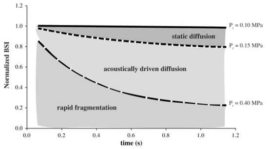
The 3 dominant mechanisms of Optison destruction.
The rapid destruction of Optison microbubbles exposed to peak negative pressures of greater than 0.4 MPa (MI = 0.21) was characteristic of the behavior described for fragmenting contrast agents in previous studies.4,6,7 At relatively high acoustic pressures (Pr > 0.4 MPa), UCAs undergo large-amplitude oscillations, resulting in shape instabilities and, ultimately, fragmentation.4,7 For Optison insonated with 2.25-MHz pulses, Dayton et al6 reported a rapid decay in echogenicity (<0.1 second) associated with fragmentation of the albumin-shelled microbubbles into smaller bubbles with diameters of less than 1 μm. Chen et al5 explored the fragmentation threshold of Optison with 1.1- and 3.5-MHz pulses of ultrasound with 10 cycle pulse durations. Their definition of fragmentation was linked to the detection of inertial cavitation. At 3.5 MHz, the Pr fragmentation threshold for Optison suspensions was 0.48 MPa. Our observation of a rapid loss of echogenicity (k > 3 s−1) occurred between a Pr threshold of 0.4 and 0.5 MPa, which is in good agreement with the previously reported threshold.
The rate of Optison destruction was directly related to Pr and MI. The pressure threshold for acoustically driven diffusion determined experimentally in this study is most applicable for Optison in static conditions. Although the experimental system in this study was not designed to match in vivo conditions, the results and the techniques developed here can serve as a foundation for experiments that test the stability of Optison within a system that more closely models physiologic conditions incorporating attenuation and flow.
In a study conducted by Forsberg et al,14 which included flow, the extent of Optison destruction did not correlate well with the displayed MI. This may have been due to a difference in the volume of Optison insonated with destructive pulses and the volume assessed for echogenicity. Optison was insonated in a flow phantom with destructive pulses from a variety of scanner/transducer combinations, and the extent of microbubble destruction was assessed with moderate-MI B-mode imaging further downstream. For a sufficiently large volumetric flow rate (which was not provided by Forsberg et al14) and a slow ultrasound imaging frame rate, contrast agent replenishment will obfuscate destruction within the ultrasound-exposed sample volume.15 The difference in the treated and imaged volumes may have allowed for inclusion of untreated microbubbles, resulting in the variability in the extent of Optison destruction reported for a constant MI. Unlike the work conducted by Forsberg et al,14 the treated and interrogated sample volumes were the same in our study; thus, the results and trends reported had less variability. The inclusion of a flow system, however, does model the in vivo environment during perfusion imaging more closely.
Forsberg et al14 used video intensity reduction from a clinical diagnostic ultrasound image to indicate contrast agent destruction. However, there was no discussion of the relationship of this video intensity reduction to bubble dynamics or mechanisms of contrast agent dissolution. Our data indicate a wide range of bubble destruction behaviors for various Pr amplitudes (Figure 8). It is important to track the video intensity over time to differentiate such complex bubble behavior so that the fragmentation and the enhanced diffusion thresholds can be distinguished from each other. The results of our study show that the MI may be used to predict the extent of UCA destruction.
In conclusion, the destruction of Optison was detected and quantified with a laboratory-assembled system and a clinical diagnostic ultrasound scanner. Total loss of Optison echogenicity occurred within 5 minutes of suspension in PBS due to static diffusion. The Pr threshold for Optison destruction due to acoustically driven diffusion at 3.5 MHz was 0.15 MPa (MI = 0.08). Peak rarefactional pressures of greater than 0.4 MPa (MI > 0.21) led to rapid destruction of Optison (within 0.5 seconds). Additionally, it was shown that the rate of Optison destruction increased with an increase in the MI of the incident pulses. When identifying a threshold for UCA destruction, it is important to identify the specific mechanism. Our method for UCA destruction identification was based on what is observed in clinical diagnostic ultrasound imaging, which is simply the loss of echogenicity within the image. The results from this study show that it is possible to identify different mechanisms of UCA destruction acoustically and to define thresholds that may be used in diagnostic and therapeutic applications of ultrasound.
Acknowledgments
We thank T. Douglas Mast, PhD, for expertise in sonographic image processing and use of his multi-purpose phantom for calibration of the Philips HDI 5000 gray scale map. This work was supported by National Institutes of Health grants NS047603-01, NS047603-01S1, HL074002-01, and HL059586-04.
Abbreviations
- BSI
backscattered intensity
- fc
center frequency
- MGSV
mean gray scale value
- MI
mechanical index
- PBS
phosphate-buffered saline
- Pr
peak rarefactional pressure
- PRF
pulse repetition frequency
- RF
radio frequency
- ROI
region of interest
- 2D
2-dimensional
- TGC
time-gain compensation
- UCA
ultrasound contrast agent
References
- 1.Wei K, Jayaweera AR, Firoozan S, Linka A, Skyba DM, Kaul S. Quantification of myocardial blood flow with ultrasound-induced destruction of microbubbles administered as a constant venous infusion. Circulation. 1998;97:473–483. doi: 10.1161/01.cir.97.5.473. [DOI] [PubMed] [Google Scholar]
- 2.Wei K, Le E, Bin JP, Coggins M, Thorpe J, Kaul S. Quantification of renal blood flow with contrast-enhanced ultrasound. J Am Coll Cardiol. 2001;37:1135–1140. doi: 10.1016/s0735-1097(00)01210-9. [DOI] [PubMed] [Google Scholar]
- 3.Eyding J, Wilkening W, Reckhardt M, et al. Contrast burst depletion imaging (CODIM): a new imaging procedure and analysis method for semiquantitative ultrasonic perfusion imaging. Stroke. 2003;34:77–83. doi: 10.1161/01.str.0000046455.51363.e2. [DOI] [PubMed] [Google Scholar]
- 4.Chomas JE, Dayton P, May D, Ferrara KW. Threshold of fragmentation for ultrasonic contrast agents. J Biomed Opt. 2001;6:141–150. doi: 10.1117/1.1352752. [DOI] [PubMed] [Google Scholar]
- 5.Chen WS, Matula TJ, Brayman AA, Crum LA. A comparison of the fragmentation thresholds and inertial cavitation doses of different ultrasound contrast agents. J Acoust Soc Am. 2003;113:643–651. doi: 10.1121/1.1529667. [DOI] [PubMed] [Google Scholar]
- 6.Dayton PA, Morgan KE, Klibanov AL, Brandenburger GH, Ferrara KW. Optical and acoustical observations of the effects of ultrasound on contrast agents. IEEE Trans Ultrason Ferroelectr Freq Control. 1999;46:220–232. doi: 10.1109/58.741536. [DOI] [PubMed] [Google Scholar]
- 7.Chomas JE, Dayton P, Allen J, Morgan K, Ferrara KW. Mechanisms of contrast agent destruction. IEEE Trans Ultrason Ferroelectr Freq Control. 2001;48:232–248. doi: 10.1109/58.896136. [DOI] [PubMed] [Google Scholar]
- 8.Thompson D, Hsu D. Technique for generation of unipolar ultrasonic pulses. IEEE Trans Ultrason Ferroelectr Freq Control. 1988;35:450–456. doi: 10.1109/58.4181. [DOI] [PubMed] [Google Scholar]
- 9.Apfel RE, Holland CK. Gauging the likelihood of cavitation from short-pulse, low-duty cycle diagnostic ultrasound. Ultrasound Med Biol. 1991;17:179–185. doi: 10.1016/0301-5629(91)90125-g. [DOI] [PubMed] [Google Scholar]
- 10.Coussios CC, Holland CK, Jakubowska L, et al. In vitro characterization of liposomes and Optison by acoustic scattering at 3.5 MHz. Ultrasound Med Biol. 2004;30:181–190. doi: 10.1016/j.ultrasmedbio.2003.10.015. [DOI] [PMC free article] [PubMed] [Google Scholar]
- 11.Sboros V, Moran CM, Pye SD, McDicken WN. Contrast agent stability: a continuous B-mode imaging approach. Ultrasound Med Biol. 2001;27:1367–1377. doi: 10.1016/s0301-5629(01)00440-9. [DOI] [PubMed] [Google Scholar]
- 12.Podell S, Burrascano C, Gaal M, Golec B, Maniquis J, Mehlhaff P. Physical and biochemical stability of Optison, an injectable ultrasound contrast agent. Biotechnol Appl Biochem. 1999;30:213–223. [PubMed] [Google Scholar]
- 13.Moran CM, Anderson T, Pye SD, Sboros V, McDicken WN. Quantification of microbubble destruction of three fluoro-carbon-filled ultrasonic contrast agents. Ultrasound Med Biol. 2000;26:629–639. doi: 10.1016/s0301-5629(00)00148-4. [DOI] [PubMed] [Google Scholar]
- 14.Forsberg F, Shi WT, Merritt CRB, Dai Q, Solcova M, Goldberg BB. On the usefulness of the mechanical index displayed on clinical ultrasound scanners for predicting contrast microbubble destruction. J Ultrasound Med. 2005;24:443–450. doi: 10.7863/jum.2005.24.4.443. [DOI] [PubMed] [Google Scholar]
- 15.Lucidarme O, Kono Y, Corbeil J, Choi SH, Mattrey RF. Validation of ultrasound contrast destruction imaging for flow quantification. Ultrasound Med Biol. 2003;29:1697–1704. doi: 10.1016/s0301-5629(03)00987-6. [DOI] [PubMed] [Google Scholar]