

Abstract
In this paper we describe interactions between neural cells and the conducting polymer poly(3,4-ethylenedioxythiophene (PEDOT) toward development of electrically conductive biomaterials intended for direct, functional contact with electrically-active tissues such as the nervous system, heart, and skeletal muscle. We introduce a process for polymerizing PEDOT around living cells and describe a neural cell-templated conducting polymer coating for microelectrodes and a hybrid conducting polymer-live neural cell electrode. We found that neural cells could be exposed to working concentrations (0.01 M) of the EDOT monomer for as long as 72 hours while maintaining 80% cell viability. PEDOT could be electrochemically deposited around neurons cultured on electrodes using 0.5-1 μA/mm2 galvanostatic current. PEDOT polymerized on the electrode and surrounded the cells, covering cell processes. The polymerization was impeded in regions where cells were well-adhered to the substrate. The cells could be removed from the PEDOT matrix to generate a neural cell-templated biomimetic conductive substrate with cell-shaped features that were cell-attracting. Live cells embedded within the conductive polymer matrix remained viable for at least 120 hours following polymerization. Dying cells primarily underwent apoptotic cell death. PEDOT, PEDOT+live neurons, and neuron-templated PEDOT coatings on electrodes significantly enhanced the electrical properties as compared to the bare electrode as indicated by decreased electrical impedance of 1-1.5 orders of magnitude at 0.01-1 kHz and significantly increased charge transfer capacity. PEDOT coatings showed a decrease of the phase angle of the impedance from roughly 80 degrees for the bare electrode to 5-35 degrees at frequencies >0.1 kHz. Equivalent circuit modeling indicated that PEDOT-coated electrodes were best described by R(C(RT)) circuit. We found that an RC parallel circuit must be added to the model for PEDOT+live neuron and neuron-templated PEDOT coatings.
Keywords: Electroactive polymer, Neural prosthesis, Interface, Electrode, Biomimetic material
1. Introduction
The use of microelectrode neural prosthetic devices in therapies for neurologic deficits is being pursued with the hope of changing the prognosis for individuals with sensory or motor impairments as well as other neurological disorders, including chronic pain, Parkinson’s disease, and epilepsy. Electrically active tissues including the brain, heart, and skeletal muscle provide opportunities to couple electronic devices and computers with human or animal tissues to create therapeutic body-machine interfaces [1]. However major road-blocks must be overcome to make implementation of such devices possible; specifically the limited biocompatibility of devices and electrodes; the weak, non-specific interactions at the neuron-electrode interface [2], and the intellectual and technological challenge of joining electronically and ionically conductive systems [3]. Therefore novel strategies must be employed to design the next generation of electrodes for bioprosthetics and biosensors. Ideally interfacial biocompatibility and electrical charge transfer can be increased by using biomimetic and adaptive electrode materials that can seamlessly integrate with tissues once implanted. Intimate neuronelectrode interfaces should also facilitate increases in the sensitivity and specificity of electrical signal transduction.
To address these issues, in recent years we and others have pursued the use of inherently conductive polymers and conducting polymer-protein composites as low electrical impedance, bioactive coatings for microelectrodes on biomedical devices [4-6]. Conjugated conducting polymers are being explored for diverse applications including light emitting diodes, thin film transistors, photovoltaic cells, anti-static coatings, biosensors, and lasers. Our laboratory has been studying the interactions between central nervous system (CNS)-derived cells and the conducting polymer poly(3,4-ethylenedioxythiophene) (PEDOT) towards the development of polymer electrodes and electrode coatings for biomedical devices [7-9]. The conductive polymerbased materials that we are developing are electrically stable over time following implantation in tissue, non-biodegradable yet biocompatible [2, 5, 10, 11]. These electrode coatings are relatively soft [12] and can be tailored at the micrometer, nanometer, and molecular scale to have fibrillar, nodular, fuzzy, tubular [13], or porous surface morphologies [14-16]. Furthermore, conducting polymers are able to efficiently accommodate charge transport into aqueous media due to mobile charge carriers and interactions with ionic dopants [17].
Significant improvements in the performance of electrode-based biomedical devices would be achieved by increasing integration at the electrode-tissue interface and by having the ability to attract target cells to the electrode site despite the presence of an immunoreaction. Neural electrode functionality can be increased by modifying the surface of the electrode sites with low impedance conductive polymer coatings with nanoscale roughness or porosity [15, 18] and through the incorporation of cell adhesion peptides [7, 19], proteins [20-22], or anti-inflammatory drugs [14, 23]. These studies suggest that the most tissue and device compatible modifications of the electrode surface would be those with electrical activity, bioactivity, mechanical softness, and topological features on a similar scale to that of cells in tissues and cell surface and extracellular matrix structures.
Here we report the in vitro polymerization of PEDOT in the presence of living neural cells. We also describe the design, synthesis, and characterization of a functional hybrid conducting polymer-neuron electrode. In past studies we have demonstrated that the microstructure of conducting polymers can be templated by dissolvable inert particles [15] and biodegradable polymer fibers [13]. We now demonstrate that PEDOT can be templated with living cells resulting in a cell-attracting, biomimetic, neuron-templated coating.
2. Materials and Methods
2.1 Cells
SH-SY5Y neuroblastoma-derived cells were maintained in Dulbecco’s Modified-Eagle’s Media (DMEM with glucose, with L-glutamine; Gibco/Invitrogen, Carlsbad, CA) supplemented with Penn-Strep mixed antibiotic solution (dilute 1:100 in cell media; Gibco/Invitrogen) and 10% fetal bovine serum (FBS; Gibco/Invitrogen). Mouse primary dissociated cortical cultures (MCC) were prepared from embryonic day 18-20 (E18-20) mice. The brains were removed and submerged in ice-cold Hanks buffered saline (HBSS; without calcium chloride, magnesium chloride, magnesium sulfate, or phenol red; Invitrogen), the neocortex was dissected, the meninges were removed, tissue was washed in ice-cold HBSS then manually dissociated with a 1 ml pipette tip. MCC were maintained in Neurobasal media supplemented with 0.5 mM L-glutamine and 2% serum-free nutritional supplement B27 (Invitrogen) at 37°C in 5% CO2. A third of the media was replaced every 4 days, and cells were allowed to mature for at least 7 days before use in experiments.
2.2 Electrodes for cell culture
Prior to exposure to cells, electrodes (bare or PEDOT-coated) were sterilized by washing in 70% ethanol (Sigma-Aldrich, St. Louis, MO) for 10 minutes. We used two different types of electrodes for these studies, custom-designed, inhouse fabricated Au/Pd sputter-coated electrodes (Au/Pd; 6 mm diameter) and Applied BioPhysics (Troy, NY) ECIS electrodes (ABP; 250 μm diameter). For the Au/Pd electrodes, it was necessary to glue the electrode to the bottom of the cell culture dish to prevent lateral movement of the electrode (1-10 ul Loctite Cyanoacrylate; Henkel Corp., Rocky Hill, CT). For cell culture, we used plasma-treated polystyrene from Corning (Corning, NY) for all experiments involving SY5Y cells and all experiments involving MCC were performed with poly(lysine) (PDL)-coated cultureware (BD Biosciences, San Jose, CA) or dishes and electrodes coated with 1 mg/ml PDL (Sigma-Aldrich) in PBS for 2-12h (then rinsed in PBS prior to cell exposure). For experiments in which PEDOT was polymerized around the living cells, the neural cells were cultured on the electrode for 24-48h prior to electrochemical polymerization process.
2.3 Electrochemical polymerization and removal of cells from PEDOT
The electrode was placed in an electrically-connected reservoir containing the aqueous monomer solution (for these studies: 0.01 M EDOT and 0.02M poly-anionic dopant poly(sodium styrene sulfonate) (PSS) in phosphate buffered saline (PBS; Hyclone Media, Logan, UT). Galvanostatic current (0.5-10 uA/mm2) was applied to the electrode and the monomer solution using an AutoLab PGstat12 Potentiostat/Galvanostat (EcoChemie, The Netherlands) for 0.5-10 minutes depending on the geometry of the electrode and the desired thickness of the polymer film. For studies on cell-templated PEDOT substrates, cells are cultured on electrodes, PEDOT was electrochemically deposited around the cells, immediately following polymerization the cells were removed by exposure to 100 mM trypsin-versene (Hyclone) at 37°C for 2h followed by mechanical disruption.
2.4 Microscopy
We used several different types of microscopy to characterize the interactions between electrodes and neural cells. 1) Optical microscopy: Nikon Optiphot POL with a Spot RT digital camera; 2) Phase contrast/fluorescence microscopy: Nikon T2000 inverted light/fluorescence microscope with Hg arc lamp, Hamamatsu CCD 16 bit camera with Simple PCI imaging software (courtesy of Takayama lab); upright Olympus BX-51 with Hg arc lamp, Olympus CCD camera, and Olympus imaging software (University of Michigan Microscopy and Image Analysis Core Laboratory, MIL); 3) Scanning Electron Microscopy (SEM) and Environmental SEM (ESEM): FEI Quanta 3D Dualbeam Focused Ion Beam (University of Michigan Electron Microbeam Analysis Laboratory, EMAL); 4) Atomic Force Microscopy (AFM): Digital Instruments Nanoscope III with a multimode head, tapping mode (EMAL).
2.5 Cell Viability Assays
Cell viability was assessed using three assays; the Vybrant Live/Dead Assay (Molecular Probes), the MTT cell viability assay (Chemicon, Temecula, CA), and immunocytochemistry (ICC) for the apoptosis associated protease, activated caspase 3 (Cell Signaling Technologies, Beverly, MA). For Vybrant Live/Dead assay cell quantity, size, and type of nuclear staining intensity were assessed by fluorescence microscopy using 3 different dyes, Hoechst 33342 (labels all cell nuclei but brighter in nuclei of apoptotic cells), YoPro-3 (labels apoptotic cells) and propidium iodide (PI) (labels cells with compromised membrane; apoptotic & necrotic cells).
2.6 Immunocytochemistry and Cell Staining
Cells were fixed in 3.7% formaldehyde/PBS at RT for 30 min-1h. For ICC, non-specific antibody binding was blocked with 3% BSA/PBS+0.1% Triton X (PBSX), primary antibodies (activated caspase 3; Cell Signaling Technology, Beverly, MA) were diluted 1:100 in blocking buffer and incubated with cells overnight at 4°C. The next day cells were washed in PBSX, incubated with secondary antibody (1:300 in blocking buffer), nuclei were counterstained with Hoechst/PBS (Molecular Probes/Invitrogen) then cells were washed, then aqueous mounted with Fluoromount G (Fisher) for imaging. The F-actin cytoskeleton was labeled by Phalloidin-Oregon Green (Molecular Probes) (1:300 in PBSX) for 1h at RT or overnight at 4°C. For fluorescence microscopy and ESEM, cells were fixed with 4% formaldehyde, maintained in PBS, then washed in water prior to imaging. For SEM cells were fixed using 1% gluteraldehyde, washed in water, then dehydrated in ascending ethanols (50%, 75%, 95%, 100%; 10 min each) then dried overnight in Peldri II or hexamethyldisilazane (HMDS) (Ted Pella, Redding, CA).
2.7 Electrical Properties Analysis
Electrical testing of electrodes was performed before and after PEDOT deposition using the AutoLab PGstat and a 3 electrode system with PBS (pH 7.0) as the electrolyte, a platinum wire as the counter electrode (CE), a saturated Ag/AgCl calomel electrode (SCE) as the reference electrode (RE). The electrode itself was the stimulating/working electrode (SE/WE). Electrochemical Impedance Spectroscopy (EIS) was used to assess the response to alternating current (AC) over a range of frequencies (1 - 100,000 Hz), paying close attention to the behavior at 100-1000 Hz, frequencies typically associated with detecting neural activity with microelectrodes [24]. Cyclic Voltammetry (CV) was used to determine the charge capacity of the electrodes. The voltage was cycled from -1 to +1 V or -0.9 to 0.5 V vs. SCE at a rate of (0.1 V/s) while the current was measured.
2.8 Equivalent Circuit Modeling
ZSimpWin (EChem Software, Ann Arbor, MI) was used to develop a circuit model from the EIS data. Data was imported from the AutoLab PGstat software, Frequency Response Analyzer (FRA). The modeling process was iterative, using the Chi-Square (χ2) value for the entire model and the percent error values for each circuit component to determine the fit of a given model to the experimental data. Components were chosen using theories from electrochemical cell studies and using the Boukamp suggestion that each component addition should reduce the χ2 value by one order of magnitude. Circuit models are presented using the Boukamp representation. The χ2 value was calculated according to the following algorithm:
| Experimental Data Point | [ωi, ai,bi] |
| Parameters Associated with Model | ρ=(ρ1,ρ2....ρm) |
| Calculated Point | [ωi,Z′i(ωi,ρ),Z″i(ωi,ρ)] |
| Weighing Factors | [ωi,W′i,W″i] |
| Chi-Square (χ2) value | |
| Wi′ = Wi″ = 1.0/(ai2 + bi2) |
The χ2 value was minimized when the experimental data points correlate with the theoretical data points. This was done by first calculating the difference between the experimental and calculated data points. The difference was squared to give larger variances a greater significance. The differences for all data points were summed and then divided by a weighing factor. As suggested by Cui, et al., a χ2 of on the order of 1X10⁻³ or below was acceptable for a given model [8].
3. Results
3.1 Determination of monomer cytotoxicity
In order to study interactions between the conducting polymer, PEDOT and neurons in vitro, we used two different types of neural cell cultures, mouse primary cortical cultures (MCC) and SH-SY5Y neuroblastoma-derived cell line (SY5Y) and two types of electrodes, custom-designed, in-house fabricated Au/Pd sputter-coated (Au/Pd; 6 mm electrode diameter) and Applied BioPhysics (Troy, NY) ECIS electrodes (ABP; 250 μm electrode diameter) adapted from techniques described in [25]. Previous studies have shown that cells can be cultured for days to weeks on conducting polymers such as PEDOT and poly(pyrrole) with little or no toxicity [10, 16, 26]. However effects of the monomer on cell viability were not known. Therefore we first determined the cytotoxicity dose-response curve for serial dilutions of the PEDOT monomer, ethylenedioxythiophene (EDOT) and the poly-anionic dopant poly(styrene sulfonate) (PSS, 0.02M). We found that both SY5Y cells and MCC could be exposed to as much as 0.01 M EDOT, 0.02M PSS for as long as 72h while maintaining at least 75% cell viability (Figure 1a). Therefore since we typically used PEDOT polymerization procedures of 30 sec-10 min. in duration, we expected cytotoxicity would be negligible.
Figure 1.


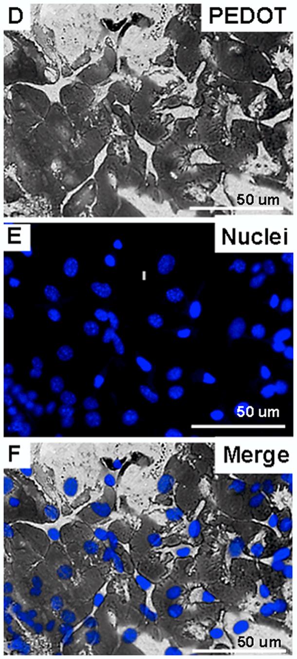
(A) MTT cytotoxicity assay for exposure of SY5Y neural cells to increasing concentrations of EDOT in monomer solution (all with 0.02 M PSS) for 0-72 hours. (B) Diagram representing the electrochemical deposition cell and the neural cell monolayer cultured on the surface of the metal electrode prior to polymerization. (C) Diagram representing PEDOT polymerized around living cells. (D) PEDOT (dark substance) polymerized in the presence of a monolayer of SY5Y neural cells cultured on an Au/Pd electrode. (E) Nuclei of SY5Y cells stained with Hoechst 33342 (blue florescence). (F) Merged image showing nuclei of cells around which PEDOT is polymerized.
3.2 Polymerization of PEDOT around living cells
To investigate whether PEDOT could be polymerized directly in the presence of live neural cells, we electrochemically deposited PEDOT using 0.5-1 uA/mm2 galvanostatic current from a monomer solution containing 0.01 M EDOT, 0.02 M PSS in PBS onto electrodes seeded with neural cells (Figure 2b-f). This resulted in formation of PEDOT on the electrode, surrounding and embedding the cells (Figures 2d-f). We assessed the morphology and topology of the PEDOT polymerized around the neural cells using optical microscopy and scanning electron microscopy (SEM). After deposition, PEDOT appeared as a dark, opaque substance around the cells and the cells and their nuclei remained intact throughout and following polymerization (Figures 2d and 2e , respectively). Interestingly, PEDOT deposition was prohibited in areas where cells were evidently strongly adhered to the substrate (see Figure 2d). Using SEM, we found that the PEDOT on the electrode and around the cells displays the fuzzy, nodular surface topology that is typical of PEDOT (Figure 2a). The polymer also appeared to wrap around the exterior of the cells and their extensions (Figure 2b-c), in some cases growing over, engulfing the cell body (see Figure 3a*).
Figure 2.
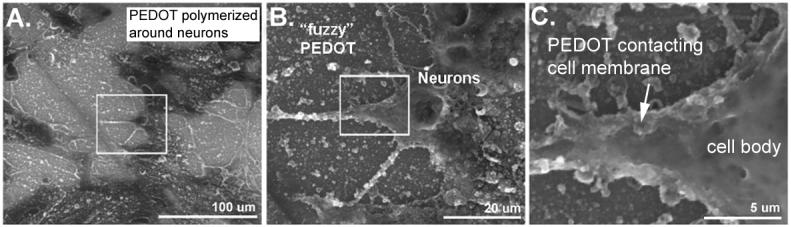
(A) PEDOT polymerized in the presence of MCC. PEDOT (rough, nodular texture) covers the Au/Pd electrode surface as well as some cellular processes. (B) Higher magnification image of area in box from part A reveals that PEDOT uses the cell membrane as a scaffold for polymerization. (C) Higher magnification image of area in box from part B further reveals the intimate electrode-cell interface resulting from polymerizing PEDOT around living neurons.
Figure 3.
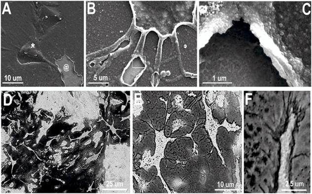

(A) SEM image of cell-templated PEDOT electrode coating prepared by enzymatic and mechanical removal of cells and cell material which reveals cell-shaped holes (@). This image also shows some cells that are completely covered and trapped in the PEDOT matrix (*). (B) Neurite-templated tunnels and crevasses are created in the PEDOT matrix by removing cells after polymerization. (C) Higher magnification image further reveals the details of the neurite tunnels and the polymer surface shows a “negative” image of the neurite membrane surface. (D) and (E) Optical images of neuron-templated PEDOT film on Au/Pd electrode shows detailed PEDOT “template” of where neurons where adhered to the substrate during polymerization. (F) PEDOT uses extracellular matrix and cell membranes as scaffolds for polymerization making possible visualization of micro and nano-filopodia allowing formation of an intimate interface between the neuron and the conductive matrix. (G) Atomic force microscopy (AFM) image of a neuron-templated PEDOT.
3.3 Generation of cell-templated PEDOT coatings
We next adapted these techniques to generate conductive polymer substrates with biomimetic topology consisting of cell-shaped holes and imprints on the same scale as cell surface features. Following polymerization of PEDOT around the neurons, the cells and cell material was removed from the PEDOT matrix using enzymatic and mechanical disruption. This resulted in a neural cell-templated, fuzzy PEDOT material with a combination of nanometer and micrometer scale features (Figures 3a-g). The neural cell-templated polymer topography included neuron-shaped holes (Figure 3a @) and tunnels, crevasses, and caves (Figure 3b-c) resulting from conductive polymer molded around cell bodies and extended neurites. Using this method, we found evidence of intimate contact at the interface between the PEDOT matrix and plasma membrane of the cells as exemplified in Figure 3f in which the PEDOT (dark substance) revealed nanometer scale tendrils at the leading edge of a neurite (Figures 3e-f). AFM images provided further details about the topology of the polymer surface, indicating that the neuron-templated features were 1.5-3 μm in height (Figure 3g).
We hypothesized that the biomimetic surface of the cell-templated PEDOT would be attractive to cells due to its nanometer scale “fuzziness” and the unique cell-shaped holes and imprints. Therefore we tested whether new cells seeded on top of the cell-templated PEDOT would show evidence of re-populating the cell-shaped holes or of increased adhesion to the cell-templated surface. We found that SY5Y cells cultured on the neuron-templated PEDOT substrate showed a preference for adhering to the cell templated zones over the regions of un-templated PEDOT (Figures 4a-c). A subset of cells did seem to re-populate the cell-shaped holes of the film (see red arrowheads in Figures 4a-c), however these cells did not settle down into the exact position as the original cells used for templating.
Figure 4.

(A) Optical image of neural cell-templated PEDOT film on Au/Pd electrode shows numerous cell-shaped holes and neurite-templated channels left behind following removal of cells from the PEDOT matrix (dark substance). (B) A new monolayer of SY5Y cells are cultured on the neuron-templated PEDOT film. These cells are stained with Phalloidin-Oregon Green (green fluorescence; F-actin) to visualize cell morphology & position of cellular processes. (C) Merged image suggests that the new cells show preferential adhesion to neuron-templated PEDOT and some cells re-populate the cell-shaped holes in the polymer film (see red arrowheads).
3.4 Assessment of cellular responses to embedding in PEDOT
To better understand cellular responses to the electrochemical polymerization procedure and embedding within the PEDOT matrix, we assessed cell viability, morphology of the cytoskeleton and nuclei, cell adhesion, and cell membrane integrity during minutes to days after polymerization. For these experiments, we used polymerization procedures which resulted in PEDOT matrices that did not completely engulf the cells so that cellular activity and access to nutrients could be retained. We found that the cells did not undergo lytic or necrotic death as evidenced by normal nuclear morphology (Hoechst 33342 staining) after the first 24h following polymerization. Therefore we assayed the cells for programmed cell death or apoptosis which can occur 24-96h following the triggering insult using the Vybrant Live/Dead assay (Invitrogen) and immunocytochemistry for activated caspase 3 (Cell Signaling Technologies), an apoptosis-associated protease. Indeed, starting at 72h following polymerization we began to detect increasing percentages of apoptosis in cells embedded in the PEDOT matrix as indicated by the presence of activated caspase 3 in the nuclei (Figures 5a-h). For example, we compared percentages of activated caspase 3 (+) cells in MCC at 0h (Figure 5c) and 120h (Figure 5h) post polymerization. Apoptotic cell counts at 0h after polymerization revealed few if any apoptotic cells however by 120h after polymerization, 25% and 33% apoptotic cells were detected in SY5Y and MCC, respectively (Figure 5i).
Figure 5.
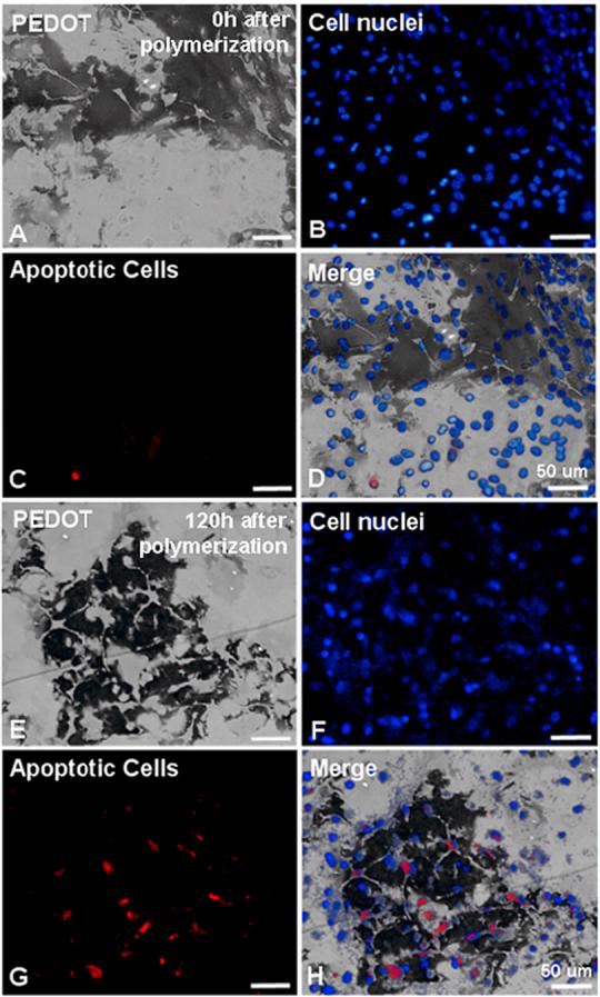
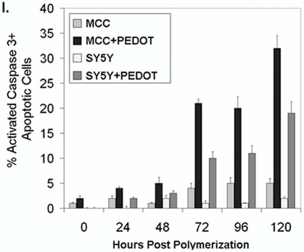
(A) Bright-field image of PEDOT (dark substance) polymerized around MCC 0h after polymerization on Au/Pd electrodes. (B) Hoechst stained (blue fluorescence) nuclei of MCC embedded in PEDOT matrix. (C) Immunocytochemical labeling of cells (+) for activated caspase 3 (apoptotic, red fluorescence). (D) Merged image shows cells embedded in PEDOT at 0h following polymerization are primarily non-apoptotic. (E) Bright-field image of PEDOT (dark substance) polymerized around MCC 120h after polymerization. (F) Hoechst stained (blue fluorescence) nuclei of MCC embedded in PEDOT matrix.. (G) Immunocytochemical labeling of cells (+) for activated caspase 3 (apoptotic, red fluorescence). (H) Merged image shows roughly 30% of MCC embedded in PEDOT are apoptotic by 120h following polymerization. (I) Bar graph comparing the percentages of cells (+) for the apoptosis marker, activated caspase 3 at 0, 24, 48, 72, 96, and 120h after polymerization of PEDOT in the presence of either SY5Y cells or MCC.
We found that the plasma membrane of the cells became permeabilized after exposure to electrical current during the electrochemical polymerization process. This was detected by staining the cells with propidium iodide (PI), a nucleic acid dye that is impermeant to cells with intact plasma membranes. The PI (+) staining was transient and by 24h there was no significant difference between electrochemically polymerized cells and controls (no current exposure) (Figure 6a and b). Figures 6c-e show the PI nuclear staining of a cluster of neural cells 30 min after PEDOT polymerization. The cells were surrounded by a thick, dense PEDOT matrix (dark, opaque substance) that covered most of the neurites leaving exposed only the tallest cell regions near the soma. In addition, cells surrounded by PEDOT for longer than a few hours showed evidence of permanent actin cytoskeleton disruption highlighted by a disruption of F-actin stress fibers as indicated by a loss of staining of the fibers using the F-actin specific dye, Phalloidin-Oregon Green. Unlike with PI (+) staining, the cytoskeletal alterations were not simply due to exposure to electrical current but rather developed within 24h following polymerization (Figure 6a and b). Abnormal F-actin staining patterns in neurons (MCC) embedded in PEDOT (thin matrix: blotchy, dark substance) were evident as early as 1h after polymerization (see Figure 6a and 6g). For comparison, the inset in Figure 6g indicates the normal F-actin staining pattern in neurons which is dominated by the presence of actin stress fibers. This is typical of cells in control samples. This phenomenon was also observed in SY5Y cells after PEDOT polymerization (Figures 7a-h). We compared F-actin staining in SY5Y cells that did not undergo PEDOT polymerization (negative control, Figure 7b) to cells 2h (Figure 7f) and 24h after polymerization (Figure 7h). Cells exposed to current alone (I control, Figure 7c) underwent some cytoskeletal changes yet these were distinct from those seen in cells surrounded by PEDOT.
Figure 6.
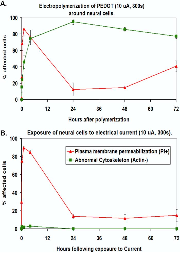

(A) Line graph showing timecourse of plasma membrane permeabilization as indicated by nuclear staining for the membrane impermeant dye, propidium iodide (red triangles; PI+) and actin cytoskeletal disruption as indicated by a loss of phalloidinstained F-actin stress fibers (green squares; Actin-) associated with electropolymerization of PEDOT around living neurons (MCC). The data are presented as percentage (%) of affected cells (either PI+ or Actin-) at 0h, 5min, 30 min, 1h, 4h, 24h, 48h, and 72h after polymerization-embedding in PEDOT. (B) Line graph showing % PI+ and Actin-cells following exposure to electrical current (no monomer present; control conditions). (C) Optical microscope image showing a thick film of PEDOT (dark substance) around MCC and partly covering their processes 30 min after polymerization. (D) PI staining (red fluorescence in nuclei) of cells embedded in PEDOT. (E) Merged image. (F) Optical image showing thin film of PEDOT around MCC 4h after polymerization. (G) Fluorescent microscope image of MCC stained with phalloidin-Oregon Green (green fluorescence) to detect F-actin. Inset shows the normal morphology of the F-actin cytoskeleton in control cells. (H) Merged image.
Figure 7.
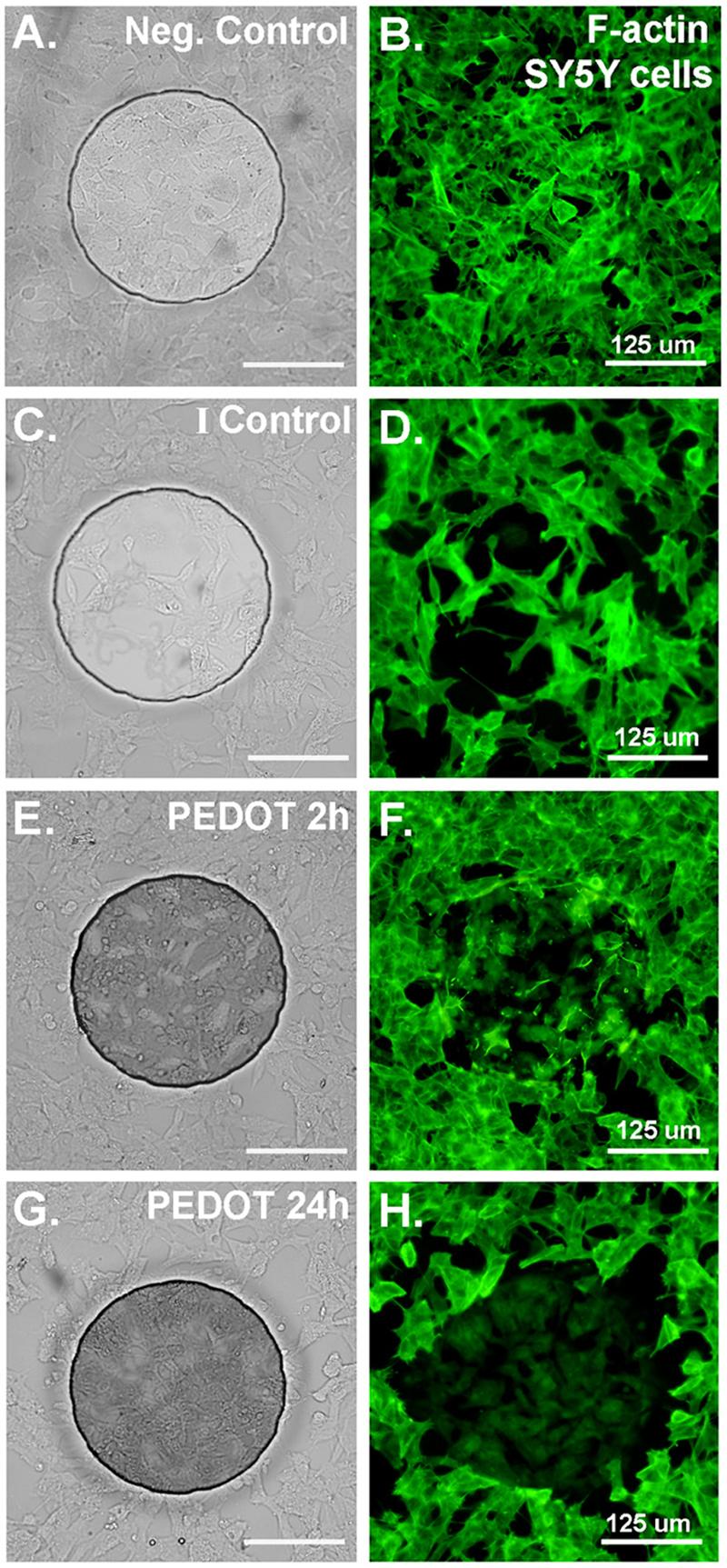
(A) Bright-field image of SY5Y cells cultured on ABP electrode (negative control; no PEDOT, not exposed to current). (B) SY5Y cells cultured on ABP electrode (negative control; no PEDOT, not exposed to current) stained for F-actin with Phalloidin-Oregon Green (green fluorescence). (C) & (D) Cells exposed to current only (no PEDOT), fixed and stained 24h after current exposure shows some morphological alterations but F-actin staining remains robust. (E) & (F) Cells 2h after PEDOT polymerization begin to show abnormal cytoskeletal staining and loss of F-actin stress fibers. (G) & (H) Cells 24h after PEDOT polymerization show a nearly complete loss of F-actin stress fibers and a decrease in the intensity of F-actin staining overall.
3.5 Characterization of the electrical properties of PEDOT containing cells
We next characterized the electrical properties of the neuron-templated PEDOT and PEDOT+live neuron electrode coatings using Electrical Impedance Spectroscopy (EIS) and Cyclic Voltammetry (CV). Recording of electrophysiological signals from electrically active cells such as neurons and cardiac myocytes are typically performed at frequency ranges from 0.1-1 kHz [27] with low impedance, sensitive electrodes which provide the highest signal to noise ratio and number of recordable units. Electrode impedance is related to interfacial surface area between the electrode and electrolyte with impedance decreasing as surface area increases. Consistent with previous reports, coating of electrodes with PEDOT results in lowering of electrode impedance 1-2 orders of magnitude across frequencies between 0.01-100 Hz [8, 9, 12] (Figure 8a). This is evidently due at least in large part to an increase in effective surface area of the electrode which is provided by the fuzzy, nano-porous yet conductive PEDOT matrix. Compared to PEDOT alone, the impedance of the PEDOT+neurons coating is increased due to the presence of the cells. This is likely associated with decreased PEDOT coverage of the electrode surface because the cells act as a barrier to PEDOT polymerization on some regions of the electrode (see Figures 3 and 4). However our finding that neural cell-templated PEDOT coatings showed impedance spectra between that of electrodes coated with PEDOT and PEDOT+neural cells suggests that some of the increased impedance of PEDOT+neurons compared to PEDOT could be due to the electrically-active nature of the cells which may interfere with signal transduction between the electrode and the PEDOT. Table 1 displays a comparison of the electrical impedance at 100 and 1000 Hz, frequencies important for neural recording and stimulating [24]. Compare the 1000 Hz impedance (Z) of the bare, uncoated electrode (4.4 kOhms) to that of an electrode seeded with neural cells (2.7 kOhms), the PEDOT-coated electrode (0.2 kOhms), the PEDOT+live neural cells electrode (1.3 kOhms), and the neural cell-templated PEDOT electrode (0.7 kOhms).
Figure 8.

(A) Impedance spectra for bare Au ABP electrodes (black squares), PEDOT-coated electrodes (blue triangles), bare Au ABP electrodes seeded with SY5Y cells (pink squares), SY5Y cells in PEDOT matrix (green triangles), and SY5Y cell-templated PEDOT (red triangles) graphed as Log Z vs. AC frequency. (B) Phase angle of the impedance for bare Au ABP electrodes (black squares), PEDOT-coated electrodes (blue triangles), bare Au ABP electrodes seeded with SY5Y cells (pink squares), SY5Y cells in PEDOT matrix (green triangles), and SY5Y cell-templated PEDOT (red triangles) graphed as phase angle (degrees) vs. AC frequency. (C) 1 kHz impedance values normalized for surface area for comparison on the same graph. ABP electrodes coated with PEDOT (blue squares), SY5Y cells in PEDOT matrix (green squares), and SY5Y cell-templated PEDOT (red squares) are compared to PEDOT coatings on electrode sites of MEMS neural probes from Xiao et al. 2003 (gray circles and Yang et al. 2004 (gray triangles).
Table 1.
The effect of PEDOT coatings on electrode impedance (kOhms).
| Electrode | 100 Hz | 1 kHz |
|---|---|---|
| Bare, un-coated | 22.6 | 4.4 |
| Neurons on bare | 21.1 | 2.7 |
| PEDOT | 0.3 | 0.2 |
| Neurons in PEDOT | 2.1 | 1.3 |
| Neuron-templated PEDOT | 1.1 | 0.7 |
The phase plot of the impedance spectroscopy reveals phase angles of 75-85° for the bare and neural cell-seeded ABP electrodes at frequencies of <10 kHz indicating that the electrode is primarily functioning as a capacitor (Figure 8b). Coating with PEDOT dramatically drops the phase angle to <20° making the electrode more resistive as opposed to capacitive at frequencies above 0.1 kHz. However the presence of neural cells within the PEDOT matrix tempers this response attenuating the decrease in phase angle so that it does not become primarily resistive until >10 kHz frequencies (see Figure 8b). This is likely due to complex interactions between the neural cell membranes which inherently have both resistive and capacitive components (usually represented by RC circuit with depolarization resistance R and membrane charge storage capacity C [27] and the unique microstructure of the PEDOT matrix that forms when PEDOT is polymerized in the presence of live cells. Similar findings were reported for electrodes coated with ordered, nanosphere-templated PEDOT [15].
To better understand how the PEDOT+neuron and neuron-templated PEDOT coatings related to PEDOT coatings in terms of their ability to decrease the electrical impedance of an electrode, we compared them to two similar PEDOT coatings that we characterized in previous publications. PEDOT+neuron and neuron-templated PEDOT coatings were compared to a PEDOT coating from Xiao et al. 2004 [4] comprised of an EDOT monomer solution containing the same poly-anionic dopant, PSS used in the present studies as well as a PEDOT coating from Yang et al. 2004 [15] that was templated with 485 nm poly(styrene) spheres using a method similar to the methods presented here for preparing cell-templated PEDOT (Figure 8c). Because we have used a variety of electrode types and geometries in our publications, for comparison purposes the data were normalized for electrode surface area (Z*A = Ohms*m2) and the 1 kHz impedance values were graphed as a function of deposition charge density (C/A = C/m2).
We have also performed equivalent circuit modeling to better understand how increasing complexity, microporosity, and non-uniformity of PEDOT coatings can dramatically affect resistivity of the PEDOT coatings. A typical bare electrode can be represented by RS(T(RTQ)) where RS is solution resistance, T is a diffusion-related finite Warburg element (constant phase element Qn=0.5), RT is charge transfer resistance at the electrode-electrolyte interface, and Q is a constant phase element representing the porosity and interfacial capacitance of the electrolyte-electrode interface. Previously, equivalent circuit models for PEDOT-coated electrodes have been defined as R(C(RTQn=0.5)) in which the T of the bare electrode is substituted for a C (capacitor) due to the diffusion of ions at the polymer surface and current conduction through the polymer that is more capacitative than for the bare electrode [8, 15, 28]. In this study modeling calculations for PEDOT, PEDOT+neurons, and neuron-templated PEDOT coatings on ABP electrodes (Figure 9ac and Table 2) indicated that the PEDOT matrix was best represented by a constant phase element Qn=0.97 for PEDOT alone, Qn=0.88 for PEDOT+neurons, and Qn=0.72 for neuron-templated PEDOT (see Table 2). This decreasing trend represents an increase in the surface porosity of the PEDOT which can be corroborated by qualitative analysis of PEDOT, PEDOT+neurons, and neuron-templated PEDOT which indicates that neuron-templated PEDOT has the highest gross porosity due to the presence of cell-shaped holes in the PEDOT matrix (see Figures 3 and 4).
Figure 9.
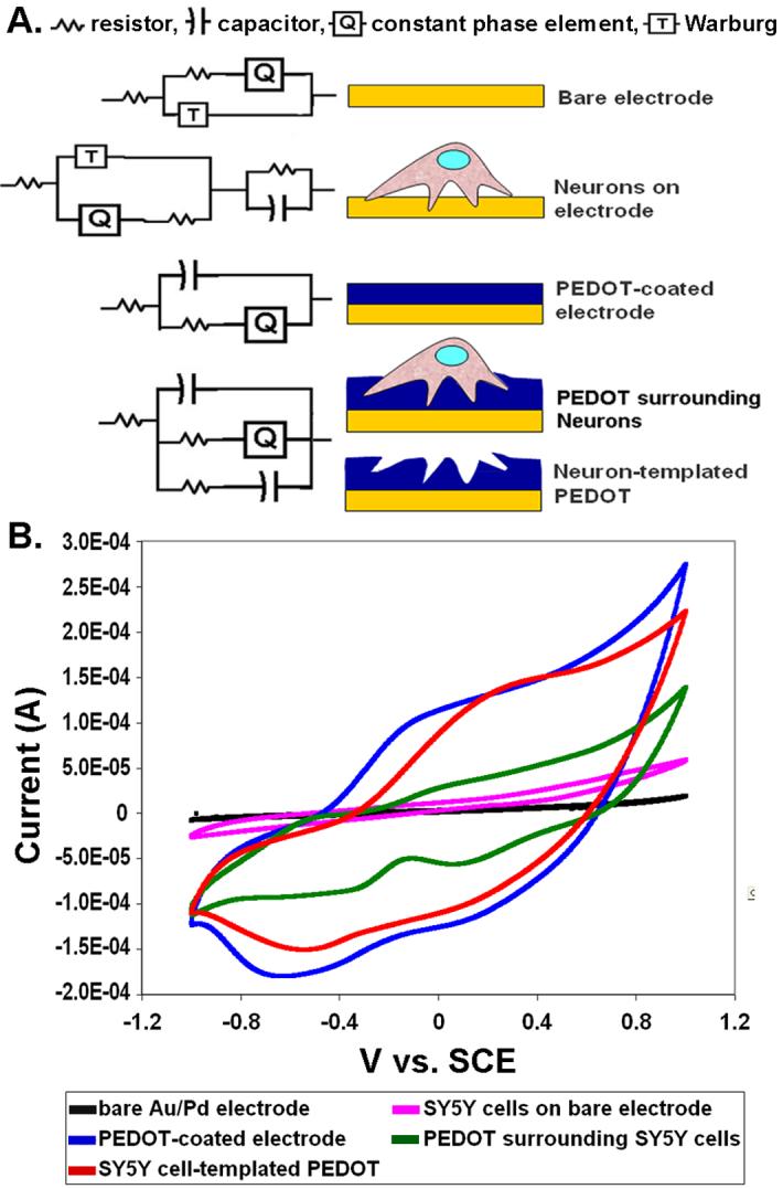
(A) Equivalent circuits representing the different electrode configurations being compared in Figures 8 and 9; bare electrode, neural cells on bare electrode, PEDOT-coated electrode, neural cells embedded in PEDOT matrix, and neural cell-templated PEDOT. (B) Cyclic voltammetry (average of 3 cycles) for bare Au/Pd electrodes (black line), bare Au/Pd electrodes seeded with SY5Y cells (pink line), PEDOT-coated electrodes (blue line), SY5Y cells in PEDOT matrix (green line), and SY5Y cell-templated PEDOT (red line) shown plotted as I vs V.
Table 2.
Equivalent circuit model values determined using ABP electrodes (electrode area 1.96 X 10⁻⁶ cm2).
| Finite Warburg | RC circuit | ||||||||||
|---|---|---|---|---|---|---|---|---|---|---|---|
| Electrode | Circuit | X2 | RS | RT | Q | n | Y0 | B | C | R | C |
| Units | Ohms*cm2 | Ohms*cm2 | S*secn/cm̫2 | Freq Power | S*sec0.5/cm̫2 | sec0.5 | F/cm2 | Ohms*cm2 | F/cm2 | Ohms*cm2 | |
| bare | R(T(RQ)) | 9.05 ×10⁻³ | 1.66×10⁻⁴ | 3.83×10⁻² | 0.115 | 0.73 | 5.91 | 3.04×10⁻³ | NA | NA | NA |
| Neurons on bare | R(T(RQ))(RC) | 2.02×10⁻³ | 1.66×10⁻⁴ | 1.25×10⁻³ | 4.07×10⁻² | 0.924 | 3.92 | 3.04×10⁻³ | NA | 0.296 | 0.205 |
| PEDOT | R(C(RQ)) | 5.32×10⁻⁴ | 1.66×10⁻⁴ | 3.52×10⁻⁴ | 6.11 | 0.97 | NA | NA | 6.98×10⁻⁴ | NA | NA |
| Neurons in PEDOT | R(C(RQ)(RC)) | 4.91×10⁻³ | 1.66×10⁻⁴ | 1.17×10⁻³ | 0.134 | 0.888 | NA | NA | 2.63×10⁻² | 3.18×10⁻³ | 0.245 |
| Neuron-templated PEDOT | R(C(RQ)(RC)) | 4.76×10⁻³ | 1.66×10⁻⁴ | 9.38×10⁻⁴ | 1.5 | 0.718 | NA | NA | 2.35×10⁻² | 7.14×10⁻³ | 0.765 |
We also found that the presence of neural cells in the PEDOT matrix contributed an RC element typical of neural cell membranes that was in parallel with the C(RQ) of the PEDOT resulting in [RS(C(RTQ)(RC))]. Interestingly the same model could be applied to neural cell-templated PEDOT yet in this case the additional RC was contributed by the capacitative gaps left behind after removal of cells from the PEDOT matrix rather than by the effects of the cell membranes. Despite having the same model, the values for both the resistor and the capacitor in the RC element are higher for the PEDOT+neuron coating (R=3.18×10⁻³ Ohms cm2, C=2.46×10⁻¹ F/cm2) as compared to the neuron-templated PEDOT coating (R=7.14*10-3 Ohms cm2, C=7.66×10⁻¹ F/cm2) (see Table 2). This increase in resistivity and capacitance manifested in an increase in charge transfer capacity that helps explain why neuron-templated PEDOT is more conductive than the PEDOT+live neuron matrix (see Figure 8a-c and Figure 9b).
CV was used to assess the charge transfer capacity of the PEDOT, PEDOT+neurons, and neuron-templated PEDOT coatings on Au/Pd electrodes (Figure 9b). The dramatic increase in charge capacity (area under CV curve) for PEDOT and neuron-templated PEDOT-coated electrodes as compared to the bare Au/P electrode is consistent with previous findings for a variety of PEDOT coatings [4, 8, 15, 29]. CV spectra show the intrinsic redox reaction of the electrode material as the potential of the electrode bias is cycled from negative to positive and back. This propels ion exchange between the electrode and the electrolyte moving mobile charge carriers in and out of the PEDOT matrix. This voltage bias switching process can be repeatedly applied to PEDOT-coatings with little or no degradation of the electrical or physical stability of the film, making PEDOT-coated electrodes ideal candidates for biosensing and drug-releasing biomaterials applications. The charge capacity for the PEDOT+neuron electrode coating is also greatly increased over the bare Au/Pd electrode seeded with neural cells but does not reach the level of that seen for PEDOT and has a distinctly different shape (see Figure 9b). The unique shape of the CV curve for PEDOT+neurons likely results from complex, as yet unknown ionic interactions and redox reactions occurring at the various interfaces between the PEDOT matrix, neuronal membranes, electrode, and electrolyte.
4. Discussion
In this paper we describe interactions between neural cell cultures and the conducting polymer PEDOT for the development of electrically conductive biomaterials intended for contact with electrically-active tissues such as the brain and heart. We investigated whether an intimate interface can be formed between living neurons and a conducting polymer toward establishment of the direct, functional contact that is required for communication between a bio-electronic device and its target tissue [30, 31]. PEDOT was electrochemically polymerized directly in the presence of neural cells seeded on electrodes resulting in the formation of a conducting polymer matrix around and onto adhered cells. SEM and optical imaging (see Figures 3-4) suggested that polymerization from a monomer solution enabled the polymer to deposit at the cell-electrode interface, apparently using the cells, cell membranes, and extracellular matrix (ECM) as scaffolds for polymerization.
Electrical characterization of the PEDOT matrix containing live neural cells suggested a relationship between the electrode and neural cells that is distinct from a more typical configuration used for electrically interfacing neurons in which neural cells are cultured on or near metal electrodes. Intimate interactions between the conducting polymer and the neuronal membrane were revealed as PEDOT covered delicate filopodia and neurites. This unique cell-polymer-electrode interface may be an ideal candidate material for the development of a new generation of biosensors and “smart” bioelectrodes. A similar concept was suggested and described by the Wallace group in studies in which the conducting polymer, poly(pyrrole) (PPy) was used to generate a novel biosensor comprised of PPy doped with erythrocytes for detection of blood Rhfactor via the Rhesus factor antigens on the cell surface [32]. The erythrocyte-containing PPy bound 3X as much antibody as compared to un-modified PPy as detected by ELISA and resistometry. This study indicates that cell-conducting polymer matrices can perform sensitive and specific biosensing. However in contrast to our study, Campbell et al. found that the presence of erythrocytes within the PPy matrix did not alter the electrical properties of the PPy. This is likely due to the fact that unlike neural cells, erythrocytes are non-adherent and non-electrically active cells. The incorporation of electrically-responsive, electrode-adherent cells into a conducting polymer matrix provides for an additional opportunity to exploit both the biochemical and electrochemical qualities of the incorporated cells for sensing purposes.
Our findings on PEDOT polymerized around cells cultured on electrodes also suggested that the process of electropolymerization around living cells may be a novel method for capturing and immobilizing cells in a fixed, conductive matrix. Trapping cells on an electrode site in PEDOT may simplify multi-electrode array (MEA)-based electrophysiological studies of signaling in neural networks which is currently made difficult by migration of neurons off electrode sites [31, 33]. It may also serve to facilitate imaging of cells using Atomic Force Microscopy (AFM) and Scanning Tunneling Microscopy (STM) which require conductive substrates and/or immobilized targets. We also noted that PEDOT polymerized around cells cultured on electrodes is a novel method for revealing a “negative” image of the morphology of the cell-substrate adhesions due to the manner in which PEDOT is deposited around the exterior of the cells (see Figures 3 and 4). This may provide an alternative to other methods for visualizing cell-substrate interactions such as immunocytochemistry and Total Internal Reflection Fluorescence (TIRF) microscopy.
Neurons partially embedded in PEDOT maintained their viability for almost 1 week suggesting that the PEDOT matrix was not a significant barrier to cell nutrient transport. However PEDOT-surrounded neurons eventually began to die by apoptosis which can be triggered as long as 24-72h after the initial insult [34]. One of the more dramatic findings in cells surrounded by PEDOT was the disruption of F-actin stress fibers. These fibers are physically and biochemically associated with integrins and other protein complexes at focal adhesions which are the primary mediators of cell surface interactions with the ECM and neighboring cells [35]. This observation provides insight about the molecular level interactions at the plasma membrane-PEDOT interface and suggests that the presence of the polymer so near the membrane may disrupt integrin signaling and focal adhesion maintenance [36]. Furthermore, loss of F-actin stress fibers is indirect evidence for the activation of biochemical signaling pathways involving focal adhesion kinase (FAK), jun-N terminal kinase (JNK), and src, each of which has been implicated in apoptosis [37]. This may explain why cells embedded in PEDOT undergo apoptosis. It also gives us molecular targets for future studies to attempt to interrupt focal adhesion disruption, block development of cytoskeletal abnormalities, and rescue cells from death. For example, we are currently exploring the possibility of performing polymerizations around cells with PEDOT co-doped with ECM/cell adhesion proteins such as laminin, fibronectin, and poly(D-lysine) and we are also in the process of synthesizing EDOT monomer that is functionalized with peptides from fibronectin and laminin) to promote specific receptor-mediated interactions between the cells and the PEDOT matrix. In addition, studies on neuronal apoptosis have also indicated that alterations in actin cytoskeletal morphology can be associated with oxidative stress in neurons [38]. The PEDOT electropolymerization process may involve production of free radicals at or near the surface of the neurons on the electrode, thus future studies will also explore whether oxidative stress plays a role in disruption of the actin cytoskeleton in neurons embedded in PEDOT.
We next generated neuron-templated PEDOT coatings by removing the cells and cell material from the PEDOT matrix after polymerization around the cells. We hypothesized that a cell-templated surface would be cytomimetic, probably biocompatible and possibly cell-attractive. Indeed the cell-defined PEDOT matrix provided surface features on the cell and neurite length-scale and included tunnels, troughs, crevasses, and caves resulting from PEDOT molded around extended neurites and various cellular processes. Our in vitro findings presented in Figure 5 suggest that when implanted in tissue, this cell-templated polymer surface may encourage cells in the host tissue to re-populate the cell-shaped holes and send processes into the tunnels and crevasses. This would provide for very intimate contact between cells and the conductive polymer making possible continuous electrical contact between the electrode and the tissue. Recent studies suggest that the use of different methods for removing the cells from the PEDOT result in variation in the amount of cell material that remains associated with the PEDOT matrix. This provides an opportunity for spatially-localized biochemical control of interactions between target cells and the electrode at the cellular and subcellular length-scale. When coupled with the mechanical control provided by the cytomimetic topology, tailoring of the biochemistry of the cell-templated surface could make possible precise manipulation and tracking of neurite guidance, growth, and signal transduction.
In past studies we have demonstrated the versatility of conducting polymers in microfabricated electrode device applications in their ability to increase electrode sensitivity and charge transport capabilities both in vivo [9, 39] and in vitro to locally deliver drugs [13] or proteins [22], and to undergo microstructure templating with dissolvable polymer nanoparticles [15] or nanofibers [13] and now, living cells. Consistent with other conducting polymer electrode coatings, the cell-templated PEDOT and PEDOT+neuron coatings described in this paper show the ability to enhance electrode functionality as indicated by decreased electrical impedance of at least 1 order of magnitude at 1 kHz and charge capacity increases of 2-4X the bare electrode. Hence, paired with their biomimetic properties, these novel electrode coatings are excellent candidate materials for improving the electrode-tissue interface.
5. Conclusions
The electroactive, biomimetic conducting polymer and hybrid conductive polymer-live cell electrode coatings that we describe here represent novel strategies for addressing short-comings at the electrode-tissue interface. This technology should help facilitate the establishment of long-term, bi-directional communication between host cells and implanted microelectrode-based biomedical devices that is critical for realization of functional body-machine interfaces. These studies serve to further elucidate the factors that are important in the design and development of novel electroactive biomaterials intended for direct, functional contact with living electrically active tissues including the CNS, heart, and skeletal muscle.
Acknowledgements
The authors would like to thank Catherine Burk for assistance with electropolymerization around cells, Joel McDonald for AFM expertise and imaging, Dr. Shuichi Takayama for use of the Nikon T2000 microscope, Dotty Sorenson and Shelly Almburg at the U of M Microscopy and Image Analysis Laboratory (MIL), and Dr. John Mansfield and Dr. Kai Sun at the U of M Electron Microscopy Analysis Laboratory (EMAL). All aspects of this study that involved use of animals or tissues obtained from animals was conducted in accordance with university policies for humane treatment of animals for research and an animal protocol is on file with the University Committee on Care and Use of Animals (UM UCUCA). Dr. Richardson-Burns was supported by a Regenerative Sciences Postdoctoral Training Grant, T90-DK070071-02. This work was also supported by NSF DMR-0084304 and NIH NINDS NO1-NS-1-2338.
Footnotes
Publisher's Disclaimer: This is a PDF file of an unedited manuscript that has been accepted for publication. As a service to our customers we are providing this early version of the manuscript. The manuscript will undergo copyediting, typesetting, and review of the resulting proof before it is published in its final citable form. Please note that during the production process errorsmaybe discovered which could affect the content, and all legal disclaimers that apply to the journal pertain.
References
- 1.Friehs GM, Zerris VA, Ojakangas CL, Fellows MR, Donoghue JP. Brainmachine and brain-computer interfaces. Stroke. 2004;35:2702–2705. doi: 10.1161/01.STR.0000143235.93497.03. [DOI] [PubMed] [Google Scholar]
- 2.Polikov VS, Tresco PA, Reichert WA. Response of brain tissue to chronically implanted neural electrodes. J Neurosci Methods. 2005;148:1–18. doi: 10.1016/j.jneumeth.2005.08.015. [DOI] [PubMed] [Google Scholar]
- 3.Fromherz P. Electrical interfacing of nerve cells and semiconductor chips. Chemphyschem. 2002;3:276–284. doi: 10.1002/1439-7641(20020315)3:3<276::AID-CPHC276>3.0.CO;2-A. [DOI] [PubMed] [Google Scholar]
- 4.Xiao YH, Cui XY, Hancock JM, Bouguettaya MB, Reynolds JR, Martin DC. Electrochemical polymerization of poly(hydroxymethylated-3,4-ethylenedioxythiophene) (PEDOT-MeOH) on multichannel neural probes. Sensors and Actuators B-Chemical. 2004;99:437–443. [Google Scholar]
- 5.George PM, Lyckman AW, LaVan DA, Hegde A, Leung Y, Avasare R, Testa C, Alexander PM, Langer R, Sur M. Fabrication and biocompatibility of polypyrrole implants suitable for neural prosthetics. Biomaterials. 2005;26:3511–3519. doi: 10.1016/j.biomaterials.2004.09.037. [DOI] [PubMed] [Google Scholar]
- 6.Brahim S, Wilson AM, Narinesingh D, Iwuoha E, Guiseppi-Elie A. Chemical and biological sensors based on electrochemical detection using conducting electroactive polymers. Microchimica Acta. 2003;143:123–137. [Google Scholar]
- 7.Xiao YH, Cui XY, Martin DC. Electrochemical polymerization and properties of PEDOT/S-EDOT on neural microelectrode arrays. J Electroanal Chem. 2004;573:43–48. [Google Scholar]
- 8.Cui XY, Martin DC. Electrochemical deposition and characterization of poly(3,4-ethylenedioxythiophene) on neural microelectrode arrays. Sensors and Actuators B-Chemical. 2003;89:92–102. [Google Scholar]
- 9.Ludwig KA, Uram JD, Yang J, Martin DC, Kipke DR. Chronic neural recordings using silicon microelectrode arrays electrochemically deposited with a poly(3,4-ethylenedioxythiophene) (PEDOT) film. J Neural Engin. 2006;3:1. doi: 10.1088/1741-2560/3/1/007. [DOI] [PubMed] [Google Scholar]
- 10.Wang X, Gu X, Yuan C, Chen S, Zhang P, Zhang T, Yao J, Chen F, Chen G. Evaluation of biocompatibility of polypyrrole in vitro and in vivo. J Biomed Mater Res. 2004;68A:411–422. doi: 10.1002/jbm.a.20065. [DOI] [PubMed] [Google Scholar]
- 11.Liang FH, Lian Z. Research and development on surface bioactivity methods of titanium and its alloys. Rare Metal Materials and Engineering. 2003;32:241–245. [Google Scholar]
- 12.Yang J, Martin DC. Impedance Spectroscopy and Nanoindentation of Conducting Poly (3,4-ethylenedioxythiophene) (PEDOT) Coatings on Microfabricated Neural Prosthetic Devices. J Mat Research. 2006 In Press:00. [Google Scholar]
- 13.Abidian MR, Kim DH, Martin DC. Conducting-Polymer Nanotubes for Controlled Drug Release. Adv Materials. 2006;18:405. doi: 10.1002/adma.200501726. [DOI] [PMC free article] [PubMed] [Google Scholar]
- 14.Kim DH, Abidian M, Martin DC. Conducting polymers grown in hydrogel scaffolds coated on neural prosthetic devices. Journal of Biomedical Materials Research Part a. 2004;71A:577–585. doi: 10.1002/jbm.a.30124. [DOI] [PubMed] [Google Scholar]
- 15.Yang JY, Martin DC. Microporous conducting polymers on neural microelectrode arrays II. Physical characterization. Sensors and Actuators A-Physical. 2004;113:204–211. [Google Scholar]
- 16.Yang JY, Kim DH, Hendricks JL, Leach M, Northey R, Martin DC. Ordered surfactant-templated poly(3,4-ethylenedioxythiophene) (PEDOT) conducting polymer on microfabricated neural probes. Acta Biomaterialia. 2005;1:125–136. doi: 10.1016/j.actbio.2004.09.006. [DOI] [PubMed] [Google Scholar]
- 17.Kaiser AB. Electronic transport properties of conducting polymers and carbon nanotubes. Reports on Progress in Physics. 2001;64:1–49. [Google Scholar]
- 18.Cui XY, Hetke JF, Wiler JA, Anderson DJ, Martin DC. Electrochemical deposition and characterization of conducting polymer polypyrrole/PSS on multichannel neural probes. Sensors and Actuators A-Physical. 2001;93:8–18. [Google Scholar]
- 19.Cui X, Lee VA, Raphael Y, Wiler JA, Hetke JF, Anderson DJ, Martin DC. Surface modification of neural recording electrodes with conducting polymer/biomolecule blends. J Biomed Mater Res. 2001;56:261–272. doi: 10.1002/1097-4636(200108)56:2<261::aid-jbm1094>3.0.co;2-i. [DOI] [PubMed] [Google Scholar]
- 20.He W, Bellamkonda RV. Nanoscale neuro-integrative coatings for neural implants. Biomaterials. 2005;26:2983–2990. doi: 10.1016/j.biomaterials.2004.08.021. [DOI] [PubMed] [Google Scholar]
- 21.Buchko CJ, Kozloff KM, Martin DC. Surface characterization of porous, biocompatible protein polymer thin films. Biomaterials. 2001;22:1289–1300. doi: 10.1016/s0142-9612(00)00281-7. [DOI] [PubMed] [Google Scholar]
- 22.Kim DH, Richardson-Burns SM, Hendricks JL, Sequera C, Martin DC. Effect of Immobilized Nerve Growth Factor (NGF) on Conductive Polymers: Electrical Properties and Cellular Response. Adv Funct Materials. 2006 In Press:00. [Google Scholar]
- 23.Zhong YH, Bellamkonda RV. Controlled release of anti-inflammatory agent alpha-MSH from neural implants. J Controlled Release. 2005;106:309–318. doi: 10.1016/j.jconrel.2005.05.012. [DOI] [PubMed] [Google Scholar]
- 24.Chapin JK. Using multi-neuron population recordings for neural prosthetics. Nat Neurosci. 2004;7:452–455. doi: 10.1038/nn1234. [DOI] [PubMed] [Google Scholar]
- 25.Wegener J, Keese CR, Giaever I. Recovery of adherent cells after in situ electroporation monitored electrically. BioTechniques. 2002;33 doi: 10.2144/02332rr01. passim. [DOI] [PubMed] [Google Scholar]
- 26.Schmidt CE, Shastri VR, Vacanti JP, Langer R. Stimulation of neurite outgrowth using an electrically conducting polymer. Proc Natl Acad Sci U S A. 1997;94:8948–8953. doi: 10.1073/pnas.94.17.8948. [DOI] [PMC free article] [PubMed] [Google Scholar]
- 27.Kovacs GTA. Enabling technologies for cultured neural networks. 1st ed. Academic Press; San Diego, CA: 1994. [Google Scholar]
- 28.Bobacka J, Lewenstam A, Ivaska A. Electrochemical impedance spectroscopy of oxidized poly(3,4-ethylenedioxythiophene) film electrodes in aqueous solutions. J Electroanal Chem. 2000;489:17–27. [Google Scholar]
- 29.Xiao YH, Martin DC, Cui XY, Shenai M. Surface modification of neural probes with conducting polymer poly(hydroxymethylated-3,4-ethylenedioxythiophene) and its biocompatibility. Appl Biochem Biotechnol. 2006;128:117–129. doi: 10.1385/abab:128:2:117. [DOI] [PubMed] [Google Scholar]
- 30.Hutzler M, Fromherz P. Silicon chip with capacitors and transistors for interfacing organotypic brain slice of rat hippocampus. Eur J Neurosci. 2004;19:2231–2238. doi: 10.1111/j.0953-816X.2004.03311.x. [DOI] [PubMed] [Google Scholar]
- 31.Merz M, Fromherz P. Silicon chip interfaced with a geometrically defined net of snail neurons. Advanced Functional Materials. 2005;15:739–744. [Google Scholar]
- 32.Campbell TE, Hodgson AJ, Wallace GG. Incorporation of erythrocytes into polypyrrole to form the basis of a biosensor to screen for Rhesus (D) blood groups and rhesus (D) antibodies. Electroanalysis. 1999;11:215–222. [Google Scholar]
- 33.Tooker A, Meng E, Erickson J, Tai YC, Pine J. Biocompatible parylene neurocages. Ieee Engineering in Medicine and Biology Magazine. 2005;24:30–33. doi: 10.1109/memb.2005.1549727. [DOI] [PubMed] [Google Scholar]
- 34.Friedlander RM. Apoptosis and caspases in neurodegenerative diseases. N Engl J Med. 2003;348:1365–1375. doi: 10.1056/NEJMra022366. [DOI] [PubMed] [Google Scholar]
- 35.Zimerman B, Volberg T, Geiger B. Early molecular events in the assembly of the focal adhesion-stress fiber complex during fibroblast spreading. Cell Motil Cytoskeleton. 2004;58:143–159. doi: 10.1002/cm.20005. [DOI] [PubMed] [Google Scholar]
- 36.Bershadsky AD, Balaban NQ, Geiger B. Adhesion-dependent cell mechanosensitivity. Annu Rev Cell Dev Biol. 2003;19:677–695. doi: 10.1146/annurev.cellbio.19.111301.153011. [DOI] [PubMed] [Google Scholar]
- 37.Reddig PJ, Juliano RL. Clinging to life: cell to matrix adhesion and cell survival. Cancer Metastasis Rev. 2005;24:425–439. doi: 10.1007/s10555-005-5134-3. [DOI] [PubMed] [Google Scholar]
- 38.Allani PK, Sum T, Bhansali SG, Mukherjee SK, Sonee M. A comparative study of the effect of oxidative stress on the cytoskeleton in human cortical neurons. Toxicol Appl Pharmacol. 2004;196:29–36. doi: 10.1016/j.taap.2003.12.010. [DOI] [PubMed] [Google Scholar]
- 39.Cui X, Wiler J, Dzaman M, Altschuler RA, Martin DC. In vivo studies of polypyrrole/peptide coated neural probes. Biomaterials. 2003;24:777–787. doi: 10.1016/s0142-9612(02)00415-5. [DOI] [PubMed] [Google Scholar]