I. INTRODUCTION
In contrast to other techniques for manipulating the intracellular environment, such as membrane permeabilization, patch pipet dialysis, or use of a cell homogenate, microinjection offers the unique advantage that precisely defined amounts of test substances can be introduced into the cytoplasm without altering other components within the cell. This chapter describes a method for microinjection of oocytes, eggs and embryos using quantitative techniques initially used by Pierre de Fonbrune in the 1930’s to inject amoeba (see de Fonbrune, 1949). These techniques were developed and applied to echinoderm eggs by Yukio Hiramoto (see Hiramoto, 1962), and have been used and further developed by many investigators (in particular, see Kiehart, 1982). This chapter describes the version used in our laboratories.
In this method, a screw-controlled syringe is used to draw solutions in and out of the tip of the micropipet. Small turns of the syringe cause displacements of fractions of a milliliter; to transform these displacements into picoliter volumes for injection, a small droplet of mercury is back-loaded then pushed to the tip of the micropipet. Behind the mercury is an air space, and an oil-filled tube leading to the syringe. Adjusting the syringe applies pressure to the air, which in turn applies pressure to the mercury. Because of the very high surface tension of mercury, large displacements of the syringe volume (on the order of 100 μl) result in very small displacementsof the volume in front of the mercury (on the order of 10 pl). This allows precise control of the injection, and as described below, precise quantitation.
To view the egg clearly during microinjection, it is held between two parallel coverslips separated by a spacer (Kiehart, 1982); for most sea urchin or starfish eggs, the spacer can be made of one or two layers of double stick tape (figure 1). The injection slide is held on the stage of an upright compound microscope, and the microinjection pipet is brought in horizontally (figure 2). With some modification, the technique can be used to inject eggs of a variety of species including ascidians (Runft and Jaffe, 2000), frogs (Runft et al., 1999), and mammals (Mehlmann and Kline, 1994; Mehlmann et al., 2002), and can also be used to inject other large cells (Terasaki et al., 1995).
Figure 1.

A side view of an egg in a microinjection slide, with a loaded injection pipet coming in horizontally.
Figure 2.
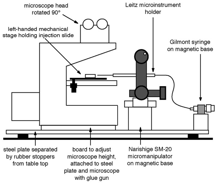
Arrangement of the microscope, micromanipulator, injection syringe, and microinstrument holder.
Many of the components needed for this method of injection are specialty items, and a major purpose of this chapter is to provide a guide to where they can be obtained. Updated information about suppliers, as well as additional technical details, information pertaining to other species of eggs, and new developments of methods will be available at http://egg.uchc.edu/injection.
II. METHODS
II.A. Preliminary Preparations
II.A.1. Assembling the apparatus
Sources of the equipment and supplies needed for these microinjection methods are listed in section III. The costly items are an upright microscope, a micromanipulator, and a horizontal micropipet puller. You also need a number of inexpensive small parts including a microinjection syringe and micropipet holder, attached to each other with a piece of teflon tubing. This assembly is filled with a fluorocarbon oil (Fluorinert).
The microinjection apparatus should be set up in a quiet location, out of the way of traffic, vibration, and distractions. A comfortable chair of the right height helps. Since many echinoderm species require cool temperatures for development, a small room with an air conditioner is ideal (see III.A.4).
To avoid vibration, the microscope as well as the micromanipulator should be firmly attached to a heavy steel plate. The plate should be positioned on a solid table or bench; vibration can be greatly reduced by placing 1–2" diameter rubber stoppers between the plate and the table at each corner (figure 2). The microscope can be attached to the plate with a glue gun, which does no harm to the microscope. Apply the glue to the solid metal of the microscope, not the rubber feet, which should be removed. Usually it is necessary to adjust the height of the microscope to match the height of the micromanipulator; this can be accomplished by using the glue gun to attach a plexiglas or wood board between the microscope and the steel plate. The micromanipulator and the microinjection syringe can be attached to the plate with magnetic bases (figure 2).
The microscope should be mounted with the front of the stage facing to the right, facing the micromanipulator. The head of the microscope (the part with the eyepieces) should be rotated 90°, such that it faces the front of the table (figure 2; see details in section III).
Finally, check that everything is level, using a small “bubble” level. Check the table, the steel plate and the microscope stage. Sometimes you will find that even with the steel plate level, the microscope stage is not. This is a common problem with Zeiss Axioskops. To fix this, you can insert a shim where the stage is mounted to the microscope body. Alternatively, for a “quick fix”, you can tilt the microinjection slide slightly, by lifting its front edge (a few tenths of a mm) such that it is not resting flat on the stage but is still held securely by the stage slide holder.
II.A.2. Cleaning coverslips
Coverslips to be used for constructing microinjection chambers must be thoroughly cleaned. New, uncleaned coverslips are highly toxic to echinoderm eggs, which you can see for yourself by attempting to fertilize eggs sitting on such a coverslip. Failure to wash coverslips is a major cause of bad results with microinjection. The following procedure should be used:
Assemble a “coverslip washer” (see section III.B.16).
Prepare a dilute solution of detergent in hot water (a pinch of Alconox in ~200 ml).
Using fine forceps, drop individual coverslips (#1 1/2, 22 × 22 mm square) into the detergent solution. Put in half of one box of coverslips. Let sit 15–30 min.
Attach the coverslip washer to the deionized water line and fill with water. Remove the lid, and using a fine forceps, transfer the individual coverslips into the water in the washing tube. Put the lid on, start the water running, and shake gently to redistribute the coverslips.
Let deionized water run through the washer for 1 hour, shaking occasionally.
Let 1–2 gallons of milliQ water run through, while shaking gently.
Using fine forceps, transfer the coverslips individually to a jar containing 85% EtOH, 15% H2O for storage.
Before use, wipe the EtOH from the coverslip using a Kimwipe.
II.A.3. Making micropipets
Using a double-stage horizontal puller, pull a micropipet. (See sections III.A.3 and III.C.10 for sources of pullers and glass tubing, as well as details on pullers and tubing dimensions.) From the shoulder to the tip, the length should be ~1 cm. It should be straight, not curved. If it is curved or too long or too short, adjust the micropipet puller. Test the pipet in the injection set up. If it works well, you may want to prepare a supply of ~10 or more pipets (keeping the same settings on the pipet puller) before continuing with the series of injections. Store pipets by attaching them to the sticky side of a pair of foam weatherstripping strips attached with double stick tape to the surface of a 150 mm Petri dish. Alternatively, use a micropipet storage jar. See section III.C.11 for further details about micropipet storage.
Using a 10 μl Hamilton syringe inserted from the back of the pipet, deposit ~1 μl of Hg so that it forms a bead in the region where the pipet begins to taper. You will later push the Hg to the tip of the pipet under microscopic observation.
II.B. Preparation of the microinjection slide
II.B.1. Initial assembly
Apply silicon grease to both sides of the U-shaped cut-out of the plastic support slide (see Begg and Ellis, 1979; Kiehart, 1982; and section III.B.9. below), so that coverslips can be attached to both sides. Attach the bottom coverslip, flush with the front of the support slide (figure 3A).
Prepare the top coverslip that will hold the eggs (figures 3B and 3C). This involves cutting a small piece of coverslip using a diamond pencil, and attaching the small piece of coverslip to the larger piece of coverslip (or an uncut coverslip) using double stick tape to form a spacer. The distance between the tape and the front of the larger coverslip piece should be ~3–5 mm. The eggs go between the 2 coverslip pieces. For different sizes of eggs, different spacers may be used (mylar of various thicknesses, see Kiehart, 1982), or coverslips may be assembled to form a wedge-shaped space (Lutz and Inoué, 1986; Kishimoto, 1986).
Figure 3.
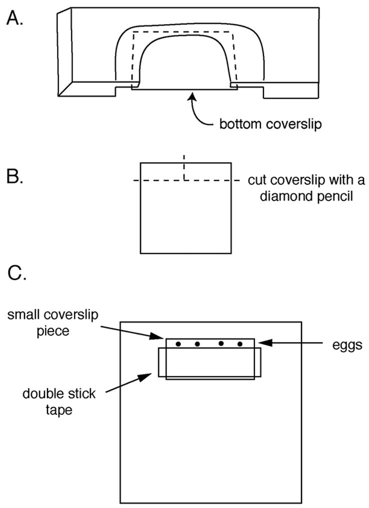
Assembly of the microinjection slide. A. The plastic support slide with the bottom coverslip attached. B. Cutting a small coverslip piece, for assembling the top coverslip. C. The top coverslip, with a piece of double stick tape and the small coverslip piece to hold the eggs.
A single piece of double stick tape produces a space about 100 μm thick (good for most sea urchin or sand dollar eggs); two pieces of tape produce a space about 200 μm thick (good for many starfish eggs). The distance between the overhanging edge of the small coverslip piece and the tape can be varied, depending on the particular use. If sperm are to be added, it is best to keep the egg chamber shallow (~200–300 μm for sea urchin eggs), since sperm do not swim well between the coverslips. Several chambers may be assembled and stored. The plastic strips from slide boxes make convenient storage racks, or use plastic Petri dishes.
II.B.2. Loading eggs into the chambers
Let the eggs settle to the bottom of a beaker or test tube. The sea water in the tube should be at 18–22 °C, not cold, as this will cause air bubbles to form. With a mouth pipet, pick up about 10 μl of a dense suspension of eggs. Deposit the suspension on the edge of the small coverslip, such that the eggs enter the chamber by capillary action. Observe by holding the coverslip up to the light, or use a stereoscope. Touching a Kimwipe to the opposite end of the chamber may help to draw in eggs.
II.B.3. Final assembly
As soon as possible after loading the eggs into the coverslip chamber, invert the coverslip and attach it to the plastic support slide by pressing it against the silicon grease. Fill the chamber with sea water. For better optics, it helps to push the top coverslip back about 1–2 mm with respect to the bottom coverslip, to eliminate the vertical air-water interface. A drop of sea water should occasionally be added to the front of the slide, since slow evaporation will occur.
II.B.4. Observation of the preparation
Check to be sure that the eggs are in good shape and not overly flattened (diameter should not be more than about 10% bigger than that of an egg outside the chamber).
II.B.5. Preparation of the loading capillary
Using a diamond pencil, cut a piece of glass tubing ~2 cm long (see section III.C.10 for tubing dimensions and ordering information). Make a clean break on the end of the capillary. This is accomplished by making a scratch on the glass and then bending the capillary back until it snaps at the scratch. Wipe the capillary glass with a Kimwipe so that it is clean. Using a P-20 pipetman, pick up ~1 μl of silicon oil. Touch the pipet tip to the end of the loading capillary and eject the oil. The oil should stay at the tip of the loading capillary. After loading the oil, load ~1 μl of the solution to be injected (as little as 0.6 μl can be used). Then load 1 μl more of oil. See figure 4A.
Figure 4.
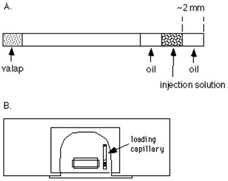
The loading capillary (A) and assembled microinjection slide (B).
Now apply a soft wax (“valap”, see section III.C.9) to the other end of the capillary to seal it. Push the end of the capillary into a dish containing the valap. Be careful not to expel the injection solution and oil. After this, wipe the oil off the outside of the capillary with a Kimwipe. Apply a dab of valap to the center of the capillary and attach it to one side of the top coverslip of the injection slide (figure 4B).
II.C. Injection
II.C.1. Mount the micropipet in the microinstrument holder
First expel any air that may be trapped in the instrument holder, by turning the micrometer syringe until oil drips out the front. Then, loosen the cap of the holder, and gently push a pipet containing a bead of mercury (section II.A.3) through the silicon tubing. See figure 5.
Figure 5.
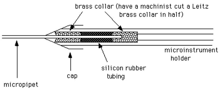
A cross-sectional view of the Leitz microinstrument holder, holding a micropipet.
If the pipet breaks in the holder, unscrew the cap, remove the front brass collar, then pull out the silicon tubing and back brass collar using a syringe needle (~20 gauge). Clean off all glass fragments carefully, and flush through some oil to clean inside the tube. If the silicon tubing is frayed, put in a new piece. To do this, first insert the back brass collar. Then insert a long piece of silicon tubing (a few cm long), and cut off flush with the front of the holder. Insert the front brass collar into the cap, and screw on the cap.
Check that the pipet is parallel to the surface of the microscope stage. If not, adjust the micromanipulator.
II.C.2. Break off the tip of the micropipet
Observe with a 10x or 20x objective. Back the injection slide out of the field of view. Bring the micropipet into view and focus on the tip, using the micromanipulator vertical control. Now back the pipet away from the field of view, and move the injection slide into view. Using the microscope focus control, focus on the edge of the loading capillary. Slowly bring the micropipet tip into the field of view, being careful not to hit the loading capillary. Then very delicately touch the tip of the micropipet to the edge of the loading capillary, to break the tip very slightly. The tip size should be about 1–3 μm (with a 10x lens, each small division in the eyepiece micrometer is 10 μm; 5 μm for a 20x lens). The optimal tip size varies for different egg species and materials being injected. Too large a tip causes damage, while too small a tip results in difficulty in loading, and clogging during injection. Starfish oocytes are particularly nice for injection because tips up to 5 μm can be used without damage.
Note that movement and focusing for the injection chamber is done with the microscope stage controls (using your left hand), while movement and focusing for the micropipet is done with the micromanipulator (using your right hand).
II.C.3. Bring the mercury to the tip of the pipet
While watching the micropipet through the microscope, advance the micrometer syringe until mercury starts to move towards the tip of the micropipet. The tip may move forward slightly during this process, so it should be moved away from the loading capillary. If the mercury doesn’t move, and the syringe pressure becomes great, the tip will start to move forward, which is the last stage before the pipet shoots out of the holder. Back off on the syringe pressure and break the tip some more by touching it again to the loading capillary edge. When the mercury does move forward, you want it to end up within a few μm of the tip; it is not necessary to bring it all the way to the end.
II.C.4. Calibrate the micropipet
Manuever the pipet tip into the oil cap of the loading capillary. Using the reticle as a measuring tool, draw up a column of oil of a known length (for instance, with a 10X objective, 50 divisions = 500 μm). To determine the volume of this column of oil, you will expel it into sea water and measure the diameter of the resulting oil drop.
First you need to bring the pipet into the chamber, between the coverslips. Move the injection pipet away from the slide. Focus on the edge of an egg in the chamber. Then move the slide out of the field of view. Move the pipet into view and focus on the tip. It is now necessary to lower the pipet tip ~60 μm, compensating for the difference in focusing through glass and water (to see the egg) and focusing through air (to see the pipet tip). With a Narishige SM-20 micromanipulator, this is accomplished by turning the height control knob ~1-1/4 turns clockwise. Now move the pipet out of the field of view, and bring the egg into view. Slowly advance the pipet towards the egg. When both pipet and egg are in view under the coverslip, adjust the vertical control on the micromanipulator to bring the pipet tip to the same focus as the edge of the egg.
Now that the pipet is in the chamber, expel oil. Measure the diameter of the oil drop and determine the volume (see Table 1). This should be 1–5% of the volume of the egg. If the oil drop volume is not as desired, go back to the loading capillary and try again with a different length of oil. For each injection to be done with this pipet, draw up the solution to the value of h determined in this calibration (figure 6).
Table 1.
Calibration table for determining injection volumes by measuring the diameter of an oil drop.
| diam (μm) | vol (pl) | diam (μm) | vol (pl) | diam (μm) | vol (pl) | diam (μm) | vol (pl) |
|---|---|---|---|---|---|---|---|
| 10 | 0.5 | 36 | 24 | 62 | 125 | 88 | 360 |
| 12 | 0.9 | 38 | 29 | 64 | 140 | 90 | 380 |
| 14 | 1.4 | 40 | 34 | 66 | 150 | 100 | 520 |
| 16 | 2.1 | 42 | 39 | 68 | 160 | 110 | 700 |
| 18 | 3.1 | 44 | 45 | 70 | 180 | 120 | 900 |
| 20 | 4.2 | 46 | 51 | 72 | 200 | 130 | 1,150 |
| 22 | 5.6 | 48 | 56 | 74 | 210 | 140 | 1,400 |
| 24 | 7.2 | 50 | 65 | 76 | 230 | 150 | 1,800 |
| 26 | 9.2 | 52 | 74 | 78 | 250 | 160 | 2,100 |
| 28 | 11.5 | 54 | 82 | 80 | 270 | 170 | 2,600 |
| 30 | 14 | 56 | 92 | 82 | 290 | 180 | 3,100 |
| 32 | 17 | 58 | 102 | 84 | 310 | 190 | 3,600 |
| 34 | 20 | 60 | 113 | 86 | 330 | 200 | 4,200 |
Volumes were calculated using the following equation:
Example: The volume of an Asterina miniata oocyte (d ~ 180 μm) is ~ 3000 pl. Therefore, an injection of 30 pl is 1% of the oocyte volume; an injection of 150 pl is 5%. Injections greater than 5% require special techniques (see Kishimoto, 1986).
Figure 6.

Calibration of the micropipet. h = the length of solution drawn into the micropipet in order to have a defined picoliter volume.
II.C.5. Load the injection solution and oil into the pipet
First, draw up some oil into the pipet; this oil will separate the mercury from the injection solution. Focus on the interface between the oil and the injection solution in the loading capillary, and move the tip of the pipet into the solution. Apply suction to draw solution into the pipet. The column of solution should have the same length as determined during the calibration. Now move the loading capillary so that the pipet tip is in the oil. Draw up a cap of oil (~10–30 divisions long), and then adjust the micrometer syringe so that there is no excess pressure or suction. Often, the oil cap is difficult to draw up. Apply extra suction and wait 30 sec. It sometimes helps to move the tip back and forth within the oil. If this doesn’t work, reduce the excess suction and break the tip some more.
II.C.6. Bring the pipet tip close to the egg
Follow the procedure described in section II.C.4 to bring the pipet into the chamber. Be prepared to adjust the micrometer syringe if the liquid in the pipet moves up the pipet when the pipet enters the sea water (a result of excess suction being left on the pipet). Bring the pipet next to the egg to be injected. Adjust the focus of the microscope to see the periphery of the egg sharply, and adjust the focus of the micromanipulator to see the tip of the pipet sharply.
II.C.7. INJECT!
Push the pipet tip into the egg. Sometimes the coverslips hold the egg sufficiently tightly that the egg doesn’t move. Other times, it is necessary to push the egg back against the double stick tape, pushing with the micropipet. The egg will dimple when the pipet is pushed against it, and then the tip will go in. The tip should be positioned near the center of the egg to avoid damage to the plasma membrane when solution is expelled. Once the pipet is in the cytoplasm, turn the micrometer syringe to expel the oil cap and injection solution. You will see the injection solution displace the cytoplasm as it moves in; if not, you may not have the tip in the egg. Stop the injection at the interface of the injection solution and the back volume of oil. It is OK if a little bit of the back volume of oil enters the egg. Then withdraw the pipet from the egg.
Observe the egg to be sure that it is not damaged, and to determine if the injected substance caused any response, such as fertilization envelope elevation. Vacuoles in the cytoplasm or lysis at the injection site indicate damage. Do a control injection (e.g., buffer only) to be sure that the injection procedure itself is not having an effect on the egg. Sometimes a control injection will cause a local elevation of a fertilization envelope at the injection site. If this happens, try using a smaller pipet tip and performing the injection more delicately.
Except for highly concentrated protein solutions, the same pipet can be used multiple times. With practice, you can expect a series of injections to require about 2 minutes per injection.
II.C.8. Culture of eggs after injection
The microinjection slide can be used as a culture and observation chamber until the embryos reach a stage where they swim away. For culturing, keep the slide in a moist environment (a Petri dish with wet Kimwipes). Alternatively, the injected eggs can be swept out of the coverslip shelf, using the micropipet, and then collected using a mouth pipet, and transferred to a separate container for culturing.
Note that the oil drop left in the egg after injection does not inhibit fertilization or development, although it is better to keep it small if the embryo is to be followed through cleavage stages.
III. EQUIPMENT AND SUPPLIES (Prices are as of December, 2002.)
III.A. Major Equipment
III.A.1. Upright microscope
A Zeiss Standard, Axioskop, or Axiostar, or a similar microscope made by another company works well. In general, the body of the microscope shouldn’t be so large that it is difficult to bring in the micromanipulator (see figure 2). The stage should move up and down to focus (vs a fixed stage design). There must be a mechanical stage for X-Y movement. Ideally, the stage should have the x-y controls on the left side. (Microscope stage controls are usually on the right side, but left hand stages are available, or the stage can be changed from right to left by a machinist. In principle, if you are left handed, you might want to set up the apparatus with a left hand micromanipulator and a right hand stage. We’ve never tried this, but it should work.) A 10x or 20x objective should be used. A Zeiss Axiostar microscope, equipped with a left hand stage and a 10x objective costs about $2000, and is an excellent microscope for this purpose. Recommended components for a typical set up are listed below; these should be modified depending on the particular application.
Carl Zeiss, Inc.
One Zeiss Drive
Thornwood, NY 10594
Phone: 1-800-233-2343
Fax: 1-914-681-7453
Website: http://www.zeiss.com/
Basic Components:
1169150 Axiostar Plus Microscope Stand; specify left-hand stage
1029023 Condenser 09/1.25 F/Axiostar
440930 CP-Achromat 10×/0.25 objective
452928 Binocular Tube 45/20 ICS
4442329902 Eyepieces (2), E-PL 10x/20 FOC/26 DIA
Other small parts as recommended by Zeiss dealer and needed for your particular use
III.A.2. Micromanipulator
A Narishige SM-20 works well. A Leitz manipulator is also very good. The manipulator must have fine controls for X, Y, and Z movements. It must be mounted securely, preferably with a magnetic base. The magnetic base from Flexbar works well; to attach the manipulator to the magnetic base, have a machinist make a small aluminum bar (figure 7).
Figure 7.
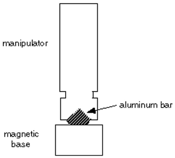
Bar for attaching the SM-20 micromanipulator to a magnetic base.
The manipulator can be ordered directly from Japan:
Narishige Scientific Instrument Laboratory
27-9 Minamikarasuyama 4-chome
Setagaya-ku, Tokyo, 157 Japan
Fax: 81-3-3308-2005
Email: sales@narishige.co.jp
Website: http://www.narishige.co.jp
Model SM-20: $4,400 including shipping. Specify: for right hand use (unless you prefer left).
(Right and left-handed manipulators are easily interconvertible: loosen the screw under the plate on the upper X-Y control. Slide the plate off and rotate 180°. Slide the plate back on and turn the knob until the screw comes up into the groove. Tighten the screw.
This manipulator is much more expensive if ordered from a U.S. distributor. The Japanese company provides excellent service; you can ship back the manipulator if service is needed.
The magnetic base can be ordered from:
Flexbar Machine Corp.
250 Gibbs Road
Islandia, NY 11722
Phone: 800-879-7575
Website: http://www.flexbar.com
Model 11002: $86
III.A.3. Micropipette puller
Horizontal pullers are generally best for pulling micropipets with a long taper, as needed for inserting the pipet between 2 parallel coverslips. Using a wide ribbon filament (~6 mm) is important for obtaining a long taper. It is also possible to use a vertical puller (see Sluder et al., 1999).
Horizonal pullers are currently sold by:
Narishige Scientific Instrument Laboratory
PN-30 Glass microelectrode puller, $2950
PN-30H Heater for PN-30, 6 mm platinum plate, pkg of 3, $162
(Recommended settings: heater = 80/81, main magnet = 78, submagnet = minimum; start here, but “fine tuning” will likely be needed.)
Sutter Instrument Company
51 Digital Drive
Novato, CA 94949
Phone: 415-883-0128
Website: www.sutter.com
P-97 Flaming/Brown type micropipet puller, $6700
For advice on the use of this puller, contact Adair Oesterle (adair@sutter.com).
Two other horizontal pullers, that are no longer sold, are often available in neurophysiology labs, and are often no longer in use:
Industrial Science Associates
Model M1
Narishige Scientific Instrument Laboratory
Model PN-3
These older model pullers make particularly nice pipets for this application, and are somewhat easier to use than the current models.
An alternative to buying a puller is to use one in another lab and make a large supply of pipets. Pulled pipets can be stored for years, with or without mercury in them (see III.C.11 below for a convenient storage device).
III.A.4. Air Conditioner
Many species of echinoderm embryos do not develop normally at room temperature (22 – 24° C) and require temperatures below 20° C. Also, in general, injection damage problems are less at cooler temperatures. For experiments that require cooling, it is possible either to cool the entire room, or to blow cool air over the microscope stage and use an incubator for storing the eggs and embryos. To cool the room, or to blow cool air over the stage, a Koldwave water-cooled air conditioner is convenient.
Often a good solution is to construct a small “microinjection room” around a Koldwave; if the room is constructed in a corner, 2" thick styrofoam insulation boards can be used to make the two other walls and ceiling. A 4′ × 5′ space is sufficient, and for this small size, 2" aluminum adhesive tape is sufficient to assemble the styrofoam boards. Styrofoam boards and aluminum tape are available from Home Depot. A curtain is adequate for a door. For a larger room, additional supports for the styrofoam should be used. Construct a frame using 2×4’s, or incorporate the backs of bookshelves to make one of the walls.
Another way to direct cool air over the microscope stage is to connect a piece of dryer duct tubing from an air conditioner that may be built in to the room. Lead the dryer duct tubing to a position near the stage.
For a supplier of Koldwave air conditioners, contact:
Koldwave Division
Heat Exchangers, Inc.
8100 N. Monticello
Skokie, IL 60076
Phone: 708-679-0300
Cost is about $1300–2000, depending on the model.
To monitor temperature inside the injection room or on the microscope stage, use a small electronic thermometer. Inexpensive electronic thermometers are sold by:
Thomas Scientific
P.O. Box 99
Swedesboro, NJ 08085
Phone: 800-345-2100
Website: www.thomassci.com
Cat.#9327-L19 ($17)
High temperature is another major cause of microinjection failure! Equipment in a small lab can heat the room well above normal “room temperature”.
III.A.5. Stereoscope
with a reticle. This is not essential, particularly if you are under 40, but is very useful for assembling microinjection chambers.
III.B. Other Equipment
III.B.1. Eyepiece micrometer reticle
For the Zeiss Axiostar, you need a 26 mm diameter disc. (Other microscopes may require slightly larger or smaller discs). The reticle should have a 10–12 mm scale (12 mm is better), divided in 100–120 divisions. Reticles can be ordered from:
Klarmann Rulings Inc.
480 Charles Bancroft Hwy.
Litchfield, NH 03052
Phone: 603-424-2401
Fax: 800-252-2401
Website: www.reticles.com
KR-221 Microscope reticle, 12 mm in 120 parts, specify diameter of disc, $62 each
III.B.2. Micrometer syringe
The Gilmont model S-1200 works well.
Barnant Co.
Gilmont Instruments Div.
28W092 Commercial Ave.
Barrington IL 60010
Phone: 800-962-7142
Website: www.barnant.com
Cat. no. GS-1200, $100
III.B.3. Magnetic stand for holding the micrometer syringe
Flexbar Machine Corp.
(address in III.A.2)
Cat. no. 11004: $30
The stand comes with a post which should be removed and replaced with a bolt, and a clamp made from a strip of 1/2" metal braid with a metal tab should be soldered on the end. Metal braid is available from electronics suppliers such as Newark. See figure 8.
Figure 8.
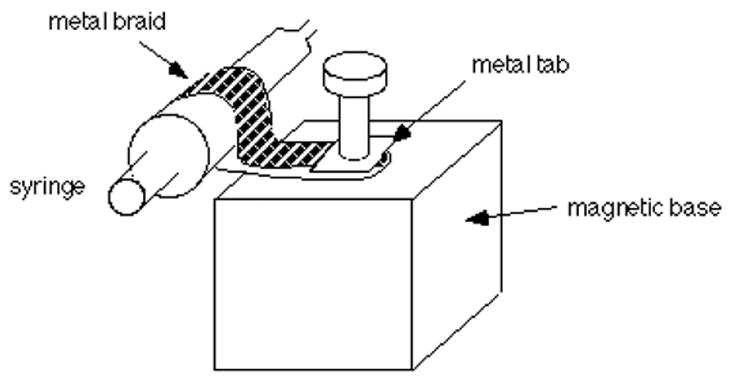
Assembly for attaching the Gilmont syringe to a magnetic base.
Another convenient way to attach the syringe to the magnetic base is with a metal hose clamp (a metal ring that tightens down with a screwdriver). Hose clamps are available in hardware stores. An aluminum clamp made for holding a broom handle to the wall can also be used.
III.B.4. Leitz microinstrument holder
Kramer Scientific Corp.
5 Westchester Plaza
Elmsford, N.Y. 10523
Phone: 845-267-5050
or
Leica Inc.
24 Link Dr.
Rockleigh, NJ 07647
Phone: 201-767-8304
Cat. no. 520145
Set of 3, $157
Also order the following replacement parts for the microinstrument holder:
W832688 Tubing replacement* $10/yard
026-350-012-007 Brass collar replacement (pressure piece) $6 each
*Specify silicon rubber tubing. Leica also supplies Tygon tubing as a replacement, but this does not work well. The silicon rubber tubing may have to be special ordered from Leica in Germany.
To hold the microinstrument holder in the SM-20 micromanipulator, have a machinist make a metal collar.
III.B.5. Syringe needle adapter
PGC Scientifics Corp.
7311 Governors Way
Frederick, MD 21704
Phone: 800-424-3300
Website: www.pgcscientifics.com
Cat. no. 79-4162-02, $15
Have a machinist attach the syringe needle adapter to the microinstrument holder.
You can do this yourself using silver solder (4% silver, 96% tin) and stainless steel soldering flux, available from:
Ed Mar/Freed
706-710 Sansom Street
Philadelphia, PA 19106
Phone: 800-346-7614
Cat. No. 54.452 Staybrite low temperature silver bearing solder and flux kit ($7)
Kester Solder (Chicago, IL) also makes this type of solder. Ordinary solder for electronics will not work for soldering brass and stainless steel. Before soldering, cut off the back of the microinstrument holder and file it down to fit in the syringe needle adapter. Apply flux, heat the metal pieces with a soldering iron, and apply solder.
III.B.6. Teflon tubing
with a CTFE hub on both ends, 1–3 ft long (2 ft is best, but 1–3 ft is OK), 20 gauge.
Scientific Commodities, Inc.
P.O. Box 2458
Lake Havasu City, AZ 86405
Phone: 800-331-7724
Website: www.scicominc.com
Cat. No. BB635-02, pkg. of 3 = $33; specify on order: 20 gauge, 24" length (custom order, 2-3 weeks)
or
Hamilton Company
P.O. Box 10030
Reno, Nevada 89520
Phone: 800-648-5950
Website: www.hamiltoncorp.com
Cat. No. 86510, $16 each (min. order of 3); specify on order: 20 gauge, 24" length.
You can also use polyethylene or teflon tubing, with cut off syringe needles pushed into the ends, for making the connections to the syringe and microinstrument holder.
III.B.7. Steel plate
24" × 18" × 1/4" is good; larger is OK, too. Steel plates can be obtained from a machine shop; a plate this size costs about $50. It is supported on rubber stoppers to prevent vibration. The plate should sit on a solid table.
III.B.8. Plexiglas or Plywood boards
These are often needed to raise the microscope to the level of the micromanipulator. The height difference is typically ~1/4"–1".
III.B.9. Microinjection chamber support slide
This is a variation of a support slide described by Kiehart (1982). It can be machined from a 3" × 1" × 1/4" piece of plexiglas (figure 9).
Figure 9.
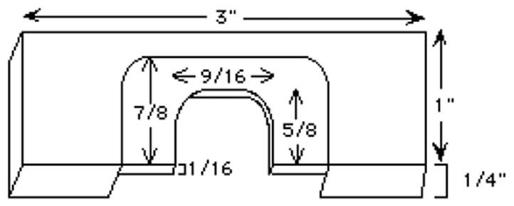
Microinjection slide dimensions.
The machinist at the Marine Biological Lab at Woods Hole has made these slides for us. Contact:
Rick Langill
Marine Biological Lab
7 MBL Street
Woods Hole, MA 02543
Phone: 508-289-7237
Cost ~$10-20 each depending on the number ordered.
See Kishimoto (1986) for an alternative design that also works well. For some microscope condensers, it is better to use a thinner slide. Slides can also be made of stainless steel or aluminum.
III.B.10. Black plexiglas sheet
(6" × 12" × 1/4") for a work surface; available from a machinist.
III.B.11. Diamond pencil
(“Glass marker, diamond-tipped”)
Thomas Scientific
III.B.12. Pipetmen
(P20 and P10)
III.B.13. Fine forceps (2)
Fine Science Tools
373-G Vintage Park Drive
Foster City, CA 94404
Phone: 800-521-2109
Website: www.finescience.com
III.B.14. Small scissors
Fine Science Tools
III.B.15. Flexible clear plastic ruler (6")
Thomas Scientific
III.B.16. Coverslip washer
made from a 50 ml polypropylene centrifuge tube, a 3′ long piece of Tygon tubing (3/8" O.D., 1/4" I.D.) and a tubing connector to attach the washer to a water line. See figure 10.
Figure 10.
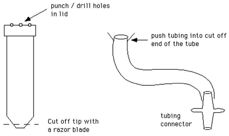
Coverslip washer.
III.B.17. Glass or polyethylene jar
for storing coverslips in 85% EtOH.
III.B.18. Mouth pipet
Mouthpieces for mouth pipets can be ordered from:
MEDTECH International/HPI Hospital
P.O. Box 162992
Altamonte Springs, FL 32716
Phone: 407-880-6904
Cat. # 1506P, white mouthpiece, pkg. of 144, $100
Unfortunately, the minimum number of pieces sold is 144.
The mouth pipet can be assembled by attaching a mouthpiece to a piece of intramedic polyethylene tubing (Clay Adams, PE-60, from Thomas Scientific). Attach the tubing to the mouthpiece as shown in figure 11.
Figure 11.
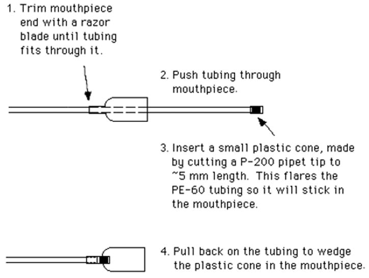
Connection of polyethylene tubing to a mouthpiece to make a mouth pipet.
Attach a piece of glass tubing (0.8 mm O.D., 0.6 mm I.D., 100 mm length, see III.C.10) to the end of the polyethylene tubing.
Another style of mouth pipet, assembled and ready to use, can be purchased from Sigma.
A5177 Aspirator tube assembly for microcapillary pipets, pkg. of 5, $8.50.
Although we prefer the design described above, the Sigma mouth pipets also work.
For some uses, it is possible to transfer eggs using a pipetman rather than a mouth pipet. A 20 μl pipetman set on 2–3 μl works well, although a mouth pipet allows better control of the number of eggs in the chamber.
III.B.19. Hamilton syringe, 10 μl
Hamilton #80300, Fisher Scientific 14-824, $20.
III.B.20. Glue gun
Hardware store (~$20).
III.B.21. Bubble level
Hardware store (~$5).
III.C. Supplies
III.C.1. Mercury
Aldrich Chemical Co., #21,545-7, 100g, $32. Another good source of clean mercury is to break a glass thermometer.
III.C.2. Silicon oil
(100 centistokes) (From Sigma: dimethylpolysiloxane, DMPS-1C, 100g, $20). Don’t use mineral oil in the micropipet; it is toxic to eggs.
III.C.3. Fluorinert oil
type FC-70 (Sigma F9880, 100 ml, $147) for filling the tubing to the syringe. Silicon oil can be used instead, and is 7X cheaper. (But don’t mix with Fluorinert!) Silicon oil is more viscous, so it tends to be messier.
III.C.4. Silicon high vacuum grease
(for assembling the injection slide). Fisher, 14-635-5D, $22.
III.C.5. Alconox detergent
(for cleaning coverslips). Fisher, 04-322-4, $14.
III.C.6. 85% EtOH
(for storing coverslips).
III.C.7. Coverslips
(No. 1/1/2 thickness, 22 mm square)
III.C.8. Double stick Scotch tape
Drugstore.
III.C.9. Valap
(a 1:1:1 mixture of beeswax, vaseline and lanolin, melted together). Beeswax is sold by Fisher. Vaseline and lanolin can be purchased at the drugstore.
III.C.10. Glass tubing
For injection pipets, use pyrex glass with an outer diameter of 1.0 mm. The glass should have a thin wall (~0.1 mm) and should not contain a filament (commonly present in glass used for electrophysiology). 50 microliter “microcaps” from Drummond work very well. These are 1.0 mm in diameter.
Drummond Scientific Company
P.O. Box 700
Broomall, PA 19008
Phone: 800-523-7480
Website: www.drummondsci.com
Cat. # 1-000-0500, $9 per vial of 100
Note that it is best to order directly from Drummond; ordering through Fisher can result in a delay of several weeks.
For mouth pipets and loading capillaries, get some slightly smaller tubing.
Cat # 9-000-1061-100 Custom Pyrex Tubing, 100 pieces per vial, O.D. 0.8 mm, I.D. 0.6 mm, length 100 mm, $13 per vial of 100 (from Drummond), minimum order of 2 vials.
III.C.11. Sticky foam weatherstripping tape
Can be purchased at the hardware store. Mount 2 strips of the weatherstripping tape with the sticky side up, with double stick tape to attach it to a 150 mm Petri dish surface. The 2 strips should be parallel to each other and ~1 cm apart. Lay pulled pipets across the 2 strips for storage; ~40 pipets can be stored in one dish. For holding the pipets securely during transport, tape a piece of foam rubber inside the lid of the Petri dish and tape the lid over the dish of pipets. You can also purchase a micropipet storage jar:
Cat. # E210 micropipet storage jar, micropipet O.D. 1.0 mm, $35 from:
World Precision Instruments
175 Sarasota Center Blvd.
Sarasota, Florida 34240
Phone: 941-371-1003
Website: www.wpiinc.com
Acknowledgments
We thank the many colleagues who passed on to us their expertise in microinjection, and who contributed to optimizing these methods. Much of the “bioengineering” described here is a legacy of Ray Kado; this chapter is dedicated to the memory of Ray.
References
- Begg DA, Ellis GW. Micromanipulation studies of chromosome movement. I Chromosome-spindle attachment and the mechanical properties of chromosomal spindle fibers. J Cell Biol. 1979;82:528–541. doi: 10.1083/jcb.82.2.528. [DOI] [PMC free article] [PubMed] [Google Scholar]
- de Fonbrune P. Technique de Micromanipulation. Masson; Paris: 1949. [Google Scholar]
- Hiramoto Y. Microinjection of the live spermatozoa into sea urchin eggs. Exp Cell Res. 1962;27:416–426. doi: 10.1016/0014-4827(62)90006-x. [DOI] [PubMed] [Google Scholar]
- Kiehart DP. Microinjection of echinoderm eggs: apparatus and procedures. Meth Cell Biol. 1982;25:13–31. doi: 10.1016/s0091-679x(08)61418-1. [DOI] [PubMed] [Google Scholar]
- Kishimoto T. Microinjection and cytoplasmic transfer in starfish oocytes. Meth Cell Biol. 1986;27:379–394. doi: 10.1016/s0091-679x(08)60359-3. [DOI] [PubMed] [Google Scholar]
- Lutz DA, Inoue S. Techniques for observing living gametes and embryos. Meth Cell Biol. 1986;27:89–110. doi: 10.1016/s0091-679x(08)60344-1. [DOI] [PubMed] [Google Scholar]
- Mehlmann LM, Kline D. Regulation of intracellular calcium in the mouse egg: Calcium release in response to sperm or inositol trisphosphate is enhanced after meiotic maturation. Biol Reprod. 1994;51:1088–1098. doi: 10.1095/biolreprod51.6.1088. [DOI] [PubMed] [Google Scholar]
- Mehlmann LM, Jones TLZ, Jaffe LA. Meiotic arrest in the mouse follicle maintained by a Gs protein in the oocyte. Science. 2002;297:1343–1345. doi: 10.1126/science.1073978. [DOI] [PubMed] [Google Scholar]
- Runft LL, Jaffe LA. Sperm extract injection into ascidian eggs signals Ca2+ release by the same pathway as fertilization. Development. 2000;127:3227–3236. doi: 10.1242/dev.127.15.3227. [DOI] [PubMed] [Google Scholar]
- Runft LL, Watras J, Jaffe LA. Calcium release at fertilization of Xenopus eggs requires type I IP3 receptors, but not SH2 domain-mediated activation of PLCγ or Gq-mediated activation of PLCβ. Dev Biol. 1999;214:399–411. doi: 10.1006/dbio.1999.9415. [DOI] [PubMed] [Google Scholar]
- Sluder G, Miller FJ, Hinchcliffe EH. Using sea urchin gametes for the study of mitosis. Meth Cell Biol. 1999;61:439–472. doi: 10.1016/s0091-679x(08)61993-7. [DOI] [PubMed] [Google Scholar]
- Terasaki M, Schmidek A, Galbraith JA, Gallant PE, Reese TS. Transport of cytoskeletal elements in the squid giant axon. Proc Natl Acad Sci USA. 1995;92:11500–11503. doi: 10.1073/pnas.92.25.11500. [DOI] [PMC free article] [PubMed] [Google Scholar]


