Abstract
Purpose
To evaluate the performance of a 17-gauge triaxial antenna at microwave ablation in an in vivo porcine liver model.
Materials and Methods
This study was approved by the institutional animal care and use committee. Thirteen female domestic pigs (mean weight, 45 kg) were used. Ablations were performed with a prototype microwave ablation system and triaxial antenna by using a constant, continuous-wave power of 68 W for 2 (n = 6), 3 (n = 6), 4 (n = 6), 5 (n = 6), 6 (n = 6), 7 (n = 13), 10 (n = 7), and 12 (n = 8) minutes. Animals were euthanized after ablation, livers were removed, and ablation zones were sliced and measured for size and roundness. A mixed linear model with animals modeled as random effects was used to test for significant differences in ablation zone metrics among time groups; post hoc tests were used to detect significant differences between time groups.
Results
Mean ablation zone diameters ranged from 2.05 cm ± 0.23 (standard deviation) at 2 minutes to 2.59 cm ± 0.53 at 12 minutes. Thirteen (32%) of 40 ablation zones with mean maximum diameters greater than 3.0 cm were observed at the 5–12-minute time groups. No significant differences in ablation zone diameter were observed among all groups (P > .05), but a trend of increasing diameter with time was noted. Mean isoperimetric ratio (a measure of roundness) for all ablation zones was 0.88 ± 0.02, which indicates minimal heat sinking near vessels.
Conclusion
The triaxial microwave ablation system is capable of creating relatively large, circular zones of ablation in minutes with minimal effects from local blood flow.
Thermal tumor ablation is a rapidly expanding treatment option for neoplasms of many organs, including the lung, liver, bone, and kidney (1–6). Tumor ablation has gained considerable attention due to its minimally invasive nature and the large number of patients who are not candidates for potentially curable surgical resection because of comorbidities or tumor number, size, or location. Radiofrequency (RF) ablation accounts for most of the clinical and experimental studies in heat-based ablation techniques (7). Unfortunately, current RF ablation systems are limited by the need to keep temperatures below 100°C to prevent charring, long ablation times, substantial deformation of the zone of ablation by vascular structures, and the need for ground pads.
Advances in Knowledge
To our knowledge, we reported the first preclinical experience of microwave ablation with a triaxial antenna.
A functional relationship between application time and ablation diameter in a normal in vivo liver model was defined.
We described a way to quantify perfusion in a zone of ablation (perfusion score).
We quantified the limited heat-sink effect with the triaxial microwave ablation antenna through circularity measurements.
Microwave ablation shares many of the advantages of RF ablation but has additional theoretic advantages that may offer better and more consistent destruction of tumors. Microwaves have a much broader field of power density and a correspondingly larger zone of active heating (8). This may allow for more uniform tumor killing within a targeted zone and, more importantly, in perivascular regions. In addition, transmission of microwave energy is not substantially hindered by desiccated or charred tissue because microwave transmission does not rely on electric conduction. Therefore, tissue temperatures may be driven considerably higher (approximately 150°C) with microwave ablation than with RF ablation (<100°C) without limiting antenna performance (9). Higher temperatures allow a larger thermal gradient to be created. In the heat equation,
| (1) |
ρ is tissue density (kilograms per cubic meter), C is specific heat (joules per kilogram Kelvin), k is thermal conductivity (watts per meter Kelvin), T is temperature (Kelvin), t is time, ∇ is the del operator, and Qh is the heat generation term (watts per cubic meter). A larger thermal gradient (∇T) increases the rate at which heat is transferred into the tissue and hence pushes the zone of ablation deeper into the tissue (Fig 1).
Figure 1.
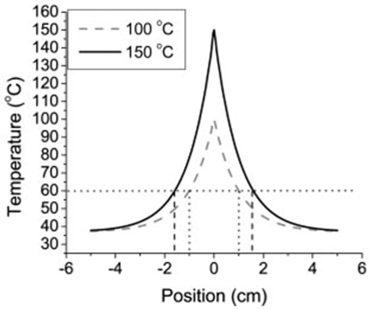
Graph of theoretic thermal profile based on Equation (1), with sources producing a temperature of either 100°C or 150°C at x = 0. When zone of ablation was defined at 60°C, 100°C source produced a 2.0-cm ablation diameter, whereas the 150°C source produced a 3.2-cm diameter. Thus, the larger thermal gradient created with 150°C source results in larger ablation zone.
Traditionally, microwave ablation has been plagued by excessive amounts of reflected power from the antenna. This increases the amount of undesirable heating in the feed cable and reduces the amount of energy deposited into the tissue. To minimize feed-cable heating, two solutions have been employed with commercial microwave systems: (a) a quarter-wave choke to reduce the amount of reflected power and (b) external cooling. Both solutions increase the diameter of a 17-gauge antenna to at least that of a 14-gauge antenna without increasing the amount of power the antenna may handle, because the feed-cable diameter (which limits input power) remains unchanged (10).
The microwave ablation system (Micrablate, Madison, Wis) used in this study has a 17-gauge tunable triaxial antenna specifically developed to minimize power reflection without adding to the diameter of the antenna (11,12). A biopsy insertion needle is used to introduce the antenna. The needle is then positioned to create a secondary source of resonance that further reduces power reflection from the antenna (Fig 2). Consequently, greater power levels may be used without compromising the small diameter of the antenna. Thus, the purpose of our study was to evaluate the performance of a 17-gauge triaxial antenna at microwave ablation in an in vivo porcine liver model.
Figure 2.
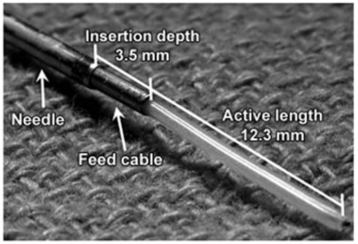
Triaxial antenna. Reflection coefficient of the antenna in liver was minimized, for an active length of 12.3 mm and an insertion depth of 3.5 mm (12).
Materials and Methods
C.L.B., D.W.v.d.W., and P.F.L. have ownership interest in Micrablate. T.M.F. and L.A.S. are consultants for Micrablate. D.W.v.d.W. is the author of U.S. patent 7,101,369, “Triaxial Antenna for Microwave Tissue Ablation.”
Animals, Anesthesia, and Overview of Procedures
Approval for our study was obtained from our institutional research animal care and use committee, and all husbandry and experimental studies were compliant with the National Institutes of Health Guide for Care and Use of Laboratory Animals (http://oacu.od.nih.gov/regs/guide/guidex.htm). Thirteen female domestic swine (Arlington Farms, Arlington, Wis) (mean weight, 45 kg) were used for this study. Animals were intubated, and anesthesia was maintained with inhaled isoflurane (Halocarbon Laboratories, River Edge, NJ). The liver was surgically exposed at laparotomy with a chevron incision to simplify antenna placement and to verify proper antenna positioning (P.F.L., 2 years of experience placing microwave ablation antennas). Microwave ablation was then performed in each of the four distinct liver lobes. After ablation was performed, animals were euthanized with an intravenous overdose of pentobarbital sodium and phenytoin sodium (Beuthanasia-D; Schering-Plough, Kenilworth, NJ). Zones of ablation were excised and sliced transversely at 3–4-mm intervals.
Microwave Ablation
All microwave ablations in this study were performed by using a single 17-gauge triaxial antenna as previously designed and characterized in an ex vivo liver model (11,12). Microwave power originated from a commercially available 2.45-GHz magnetron generator (MG0300D; Cober-Muegge, Norwalk, Conn) capable of delivering up to 300 W of continuous-wave power. Use of the generator allowed continuous forward and reflected power monitoring within a ±0.3-W margin of error. Radiograde coaxial cables with subminiature A connectors (RG400/U; Pasternack Enterprises, Irvine, Calif) were used to transfer power from the generator to the antenna.
Prototype triaxial antennas tuned for liver tissue were introduced and placed by using a 17-gauge (1.5-mm-diameter) biopsy needle (Tru-Guide; Bard Medical, Covington, Ga). The triaxial antenna is formed when the biopsy needle is positioned 3.5 mm back from the active length; this aids in reducing the reflection coefficient of the antenna (Fig 2). The low power reflection from the triaxial antenna allows the full power rating of the cable to be used. A pack of ice was used as a precautionary measure to cool the subminiature A connector between the coaxial cable and the semirigid antenna feed cable to eliminate potential connector failures caused by thermal expansion inside the connector. High-quality connectors would alleviate the need for such cooling.
With the described system, zones of ablation were created by applying approximately 68 W to the antenna. Power was applied continuously for 2 (n = 6), 3 (n = 6), 4 (n = 6), 5 (n = 6), 6 (n = 6), 7 (n = 13), 10 (n = 7), and 12 minutes (n = 8). Forward and reflected powers were recorded every second with the generator. At least one ablation was performed in each lobe of each porcine liver. Some lobes were large enough to accommodate an additional ablation zone. An additional ablation was performed only if separation of 2 cm from the initial ablation zone could be maintained and was always performed proximal to the initial ablation in that lobe so that perfusion was not diminished. Thus, 58 ablations were performed in 52 liver lobes. Potential bias caused by variations in hepatic perfusion between lobes was reduced by alternating the liver lobe in which ablations in a given time group were performed. Newly fabricated antennas were used on each animal, with the exception of animals in the 10-minute time group. Only previously used antennas were available for that time group. Average reflected power measured with the generator remained less than 4% throughout the study. We observed no major complications during the study.
Measurement of Ablation Zone Size and Shape
Ablation zone slices were optically scanned (Perfection 2450 Photograph, model G860A; Epson, Long Beach, Calif) and saved as electronic images. For each zone of ablation, a representative slice near the middle of the active length of the antenna was chosen (P.F.L., C.L.B.). Standard ablation zone metrics, such as diameter, isoperimetric ratio (IR), and number and size of vessels, were analyzed (C.L.B., P.F.L.) by using free software (ImageJ; National Institutes of Health, Bethesda, Md). Maximum and minimum diameters were measured from the zone of complete necrosis, not from the surrounding zone of partial necrosis (13). Ablation zone diameters were determined by using lines running through the insertion needle track of the representative slice. IR is a measure of the roundness of an ablation zone, according to the equation IR = 4π · A/P2, where area (A) and perimeter (P) are measured from the same representative slice (14,15). An IR of 1.0 indicates a perfect circle. We used IR to quantify the effect of vessels and perfusion on ablation zone shape. IRs closer to 1.0 indicated minimal heat sinking, whereas IRs closer to 0.0 indicated more heat sinking.
To quantify the effect of flow in vessels on ablation zone size, we measured the radial distance from the antenna track to vessel centers and the vessel diameters (Fig 3). Only vessels larger than 1 mm in diameter and within 2.0 cm of the antenna in the representative slice from each zone of ablation were considered. The value of 1 mm was chosen on the basis of past experience indicating that vessels smaller than 1 mm are coagulated quickly and provide little or no heat-sinking effect. The value of 2.0 cm was used on the basis that ex vivo zones of ablation are rarely larger than 4.0 cm in diameter and numeric predictions that in vivo zones of ablation would be 20%–30% smaller because of the effects of perfusion (11). A perfusion score (Sp) was then calculated foreach representative slice according to the equation
Figure 3.
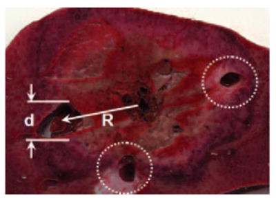
Diagram of perfusion scoring of typical ablation zone. For each vessel, the distance from ablation track to vessel center (R) and vessel diameter (d) were recorded and input into Equation (2). Dotted lines indicate other vessels scored for this ablation zone. Total perfusion score for each ablation was the sum of scores for all vessels.
| (2) |
where Rn indicates the radial distance (in centimeters) from the antenna to the center of vessel n, and dn indicates the diameter (in millimeters) of vessel n. Equation (2) was best fit from numeric simulations of the effects of vessels on heat transfer.
Statistical Analysis
The statistical mean ± standard deviation of each metric (minimum and maximum diameter, area, and IR) were calculated for each time point. A mixed model, with time considered fixed and animals modeled as random effects, was used to test for significant differences in ablation zone size and IR among time groups by using software (SAS, version 8.0; SAS Institute, Cary, NC). A P value of .05 was considered to indicate a significant difference.
Results
Three antennas failed during this study, as noted by mechanical breaking of the inner conductor, and the resulting zones of ablation were discounted. No connector failures were encountered.
Ablation Zone Diameter
We observed a trend of increasing diameter with time (Table, Fig 4), with the slope curve decreasing with time. The mixed model revealed no significant differences in mean ablation zone diameters among time groups (P > .05), but results of post hoc analysis showed that the mean maximum diameter at 12 minutes was significantly larger than that at 2 minutes (P < .05) (Fig 5). Thirteen (32%) of 40 ablation zones in the 5–12-minute time groups had mean maximum diameters greater than 3.0 cm (Fig 6). Increases in mean ablation zone diameter at each subsequent ablation time diminished for times longer than approximately 5 minutes.
Table.
Microwave Ablation Zone Measurements in Livers of 13 Swine from Use of 17-gauge Triaxial Antenna and 68 W Input Power at Different Application Times
| Application Time (min) | No. of Ablations | Minimum Diameter (cm)* | Maximum Diameter (cm)* | Mean Diameter (cm)* | IR* | Perfusion Score* |
|---|---|---|---|---|---|---|
| 2 | 6 | 1.70 ± 0.28 | 2.25 ± 0.25 | 2.05 ± 0.23 | 0.90 ± 0.02 | 0.63 ± 0.58 |
| 3 | 6 | 1.83 ± 0.42 | 2.24 ± 0.49 | 2.06 ± 0.42 | 0.88 ± 0.03 | 1.13 ± 0.66 |
| 4 | 6 | 1.98 ± 0.40 | 2.56 ± 0.30 | 2.27 ± 0.33 | 0.86 ± 0.04 | 1.08 ± 0.49 |
| 5 | 6 | 2.33 ± 0.48 | 2.63 ± 0.52 | 2.50 ± 0.48 | 0.89 ± 0.06 | 0.98 ± 0.98 |
| 6 | 6 | 2.10 ± 0.37 | 2.58 ± 0.41 | 2.37 ± 0.38 | 0.91 ± 0.028 | 1.50 ± 0.89 |
| 7 | 13 | 2.06 ± 0.49 | 2.67 ± 0.51 | 2.39 ± 0.38 | 0.87 ± 0.06 | 1.16 ± 1.18 |
| 10† | 7 | 1.25 ± 0.26 | 2.27 ± 0.25 | 2.07 ± 0.25 | 0.87 ± 0.03 | 1.90 ± 0.59 |
| 12 | 8 | 2.29 ± 0.45 | 2.89 ± 0.59 | 2.59 ± 0.53 | 0.86 ± 0.04 | 1.84 ± 0.86 |
Data are mean ± standard deviation.
Anomalous points at 10 minutes are likely because of the high perfusion rate and the large number of previously used antennas applied in this time group.
Figure 4.
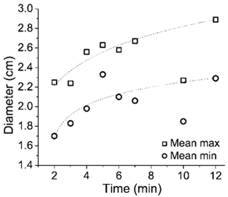
Graph of mean minimum (min) and maximum (max) ablation zone diameter versus application time. Logarithmic dependence on application time similar to results of previous numeric and ex vivo studies was seen (11). Relatively small increases in ablation diameter were seen after 5 minutes. Anomalous points at 10 minutes are thought to be caused by an abnormally high perfusion rate and overused antennas.
Figure 5.
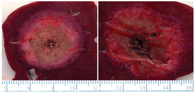
Left: Representative slice at 2 minutes. Right: Representative slice at 12 minutes. Average ablation zone diameter was significantly larger at 12 minutes than at 2 minutes. Note highly circular shape of each ablation zone and lack of deflection caused by local blood flow. Input power was 68 W in both cases.
Figure 6.
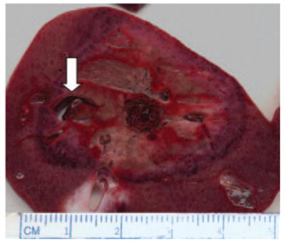
Ablation zone of 3.6 × 3.2 cm created with triaxial antenna. In this case, a vessel approximately 5 × 9 mm was able to be coagulated (arrow).
IR and Perfusion Score
Mean IR (0.88 ± 0.02) was consistently high at all time points, and the mean IR at each time point was greater than 0.80 (Table). The perfusion score was highest at 10 minutes, but large values also were noted for the 6- and 12-minute time groups. A mixed model analysis revealed no significant differences in IR (P > .05) or perfusion score (P > .05) among time groups, but we observed a trend of slightly decreasing IR for increases in application time. In fact, post hoc analysis revealed that the IR at 12 minutes was significantly smaller than that at 2 minutes (P < .05). In addition, some blood vessels up to 7 mm in diameter were coagulated (Fig 6).
Discussion
To our knowledge, ours is the initial in vivo experience of microwave ablation with a small-diameter triaxial antenna. The zones of ablation produced with this system appear to be larger than those produced with any other single-needle, nondeployable thermal applicator appropriate for percutaneous use. In vivo zones of ablation created with other percutaneous microwave ablation systems (13–14 gauge) have been limited to average diameters of approximately 1.0–1.8 cm for 2–10-minute ablations (9,16,17). Similarly, the average diameter produced by using a 17-gauge RF ablation system (Cool-tip; Valleylab, Boulder, Colo) with a 12-minute ablation time was 1.8 cm (18). In our study, an average diameter of 2.05 cm ± 0.23 in 2 minutes and 2.59 cm ± 0.53 in 12 minutes was achieved with a single 17-gauge antenna. Thus, the use of the triaxial antenna presents an increased ability to treat larger tumors with a potential time savings and/or with less invasiveness compared with that of commercial RF ablation and microwave devices of similar size.
IR was used to quantify the degree of effect vessels had on the overall ablation zone shape. The average IR measured in this study (0.88) represents a minimal effect of vascular heat sinking on zones of ablation. By comparison, an average IR of 0.78 for 12-minute ablations with a single Cool-tip electrode has been noted in the same porcine model (19). The reduced heat-sink effect is likely due to the increased heat generation of microwave energy compared with that of RF energy (20). We believe the slight drop in IR with time was caused by the increased dependence of ablation zone shape on thermal conduction when ablation times greater than 2–3 minutes were used. As the zone of ablation is created, the peripheral border is heated for less time and with a smaller thermal gradient than tissue close to the antenna; therefore, the ablation boundary at longer treatment times is more subject to heat sinking than that at shorter times. All ablation zones will eventually be limited by perfusion because the heat being delivered to the periphery of the ablation zone can no longer overcome heat lost to blood flow, regardless of the tissue temperature immediately adjacent to the applicator.
The coaxial cable dielectric is subject to increased loss when large heating cycles are repeated (21). The result of excessive heating and cooling can be reduced antenna efficiency, lower energy deposition, and, potentially, antenna failure. The three antenna failures encountered in this study may have been because of overuse or fabrication errors in these handmade antennas; failures were observed only in previously used antennas. Subsequent zones of ablation created with the same antenna tend to be slightly decreased in diameter compared with former zones (11). Thus, no antenna was used in more than one animal.
Limitations in other microwave antenna designs have prompted considerable interest in improvements that will allow more widespread clinical use. These include smaller-gauge antennas to encourage minimally invasive applications, limited feed-cable heating, and ease of use. The goal of the triaxial antenna design is to reduce the amount of reflected power without increasing invasiveness or complexity. The biopsy needle used to insert the antenna is positioned approximately one-quarter wavelength back from the feed point. This provides a mechanism to reduce the reflected power without increasing the size of the antenna. Feed-line heating caused by reflected power is minimized, and power throughput into the tissue is maximized. Consequently, the ratio of power to antenna diameter is also maximized.
A limitation of this study was the lack of a large-animal tumor model to determine the performance of the triaxial antenna in primary and secondary liver tumors. Such tumor models do exist, but they are costly, complicated, and may not be applicable to the study of human hepatic tumors encountered in clinical practice. We performed our ablations at laparotomy in an effort to maximize the number of ablation zones per animal. The lack of complications indicates this procedure to be safe for the open surgical environment. However, the trend in clinical practice is toward smaller, less invasive applicators that can be used in a percutaneous fashion. Because this 17-gauge antenna was specifically designed for percutaneous use, further percutaneous study seems warranted.
Practical application
Our results demonstrated the ability to consistently achieve clinically relevant zones of ablation by using a prototype small-gauge triaxial microwave antenna in an in vivo porcine liver model. This system enabled us to treat areas larger than those treated with current microwave and RF devices in clinical use. The increased ablation zone size and decreased dependence on heat sinking may hold promise for use of this system as a treatment option for hepatic tumors, particularly those near vascular structures. The ability to use multiple microwave antennas simultaneously may make this system even more attractive for treatment of large tumors. Application of the triaxial antenna in a multiple-antenna format should be the topic of another investigation.
Acknowledgments
The authors thank Rajat Mukherjee, MS, for his assistance with statistical analysis and manuscript revisions.
Abbreviations
- IR
isoperimetric ratio
- RF
radiofrequency
Footnotes
See Materials and Methods for pertinent disclosures.
References
- 1.Farrell MA, Charboneau WJ, DiMarco DS, et al. Imaging-guided radiofrequency ablation of solid renal tumors. AJR Am J Roentgenol. 2003;180:1509–1513. doi: 10.2214/ajr.180.6.1801509. [DOI] [PubMed] [Google Scholar]
- 2.Zagoria RJ. Imaging-guided radiofrequency ablation of renal masses. RadioGraphics. 2004;24(suppl 1):S59–S71. doi: 10.1148/rg.24si045512. [DOI] [PubMed] [Google Scholar]
- 3.Steinke K, Sewell PE, Dupuy D, et al. Pulmonary radiofrequency ablation: an international study survey. Anticancer Res. 2004;24:339–343. [PubMed] [Google Scholar]
- 4.Davis KW, Choi JJ, Blankenbaker DG. Radiofrequency ablation in the musculoskeletal system. Semin Roentgenol. 2004;39:129–144. doi: 10.1016/j.ro.2003.10.002. [DOI] [PubMed] [Google Scholar]
- 5.Cioni R, Armillotta N, Bargellini I, et al. CT-guided radiofrequency ablation of osteoid osteoma: long-term results. Eur Radiol. 2004;14:1203–1208. doi: 10.1007/s00330-004-2276-6. [DOI] [PubMed] [Google Scholar]
- 6.Gillams AR. Liver ablation therapy. Br J Radiol. 2004;77:713–723. doi: 10.1259/bjr/86761907. [DOI] [PubMed] [Google Scholar]
- 7.Ahmed M, Goldberg SN. Image-guided tumor ablation: basic science. In: vanSonnen-berg E, McMullen W, Solbiati L, editors. Tumor ablation: principles and practice. New York, NY: Springer; 2005. p. 542. [Google Scholar]
- 8.Skinner MG, Iizuka MN, Kolios MC, Sherar MD. A theoretical comparison of energy sources—microwave, ultrasound and laser—for interstitial thermal therapy. Phys Med Biol. 1998;43:3535–3547. doi: 10.1088/0031-9155/43/12/011. [DOI] [PubMed] [Google Scholar]
- 9.Wright AS, Lee FT, Jr, Mahvi DM. Hepatic microwave ablation with multiple antennae results in synergistically larger zones of coagulation necrosis. Ann Surg Oncol. 2003;10:275–283. doi: 10.1245/aso.2003.03.045. [DOI] [PubMed] [Google Scholar]
- 10.Lin JC, Wang YJ. A cap-choke catheter antenna for microwave ablation treatment. IEEE Trans Biomed Eng. 1996;43:657–660. doi: 10.1109/10.495286. [DOI] [PubMed] [Google Scholar]
- 11.Brace CL, Laeseke PF, van der Weide DW, Lee FT. Microwave ablation with a triaxial antenna: results in ex vivo bovine liver. IEEE Trans Microw Theory Tech. 2005;53:215–220. doi: 10.1109/TMTT.2004.839308. [DOI] [PMC free article] [PubMed] [Google Scholar]
- 12.Brace CL, Laeseke PF, van der Weide DW, Sampson LA, Lee FT. Analysis and validation of a triaxial antenna for microwave tumor ablation. IEEE MTT-S Int Microw Symp Dig. 2004;3:1437–1440. doi: 10.1109/MWSYM.2004.1338842. [DOI] [PMC free article] [PubMed] [Google Scholar]
- 13.Goldberg SN, Grassi CJ, Cardella JF, et al. Image-guided tumor ablation: standardization of terminology and reporting criteria. Radiology. 2005;235:728–739. doi: 10.1148/radiol.2353042205. [DOI] [PMC free article] [PubMed] [Google Scholar]
- 14.Chinn SB, Lee FT, Jr, Kennedy GD, et al. Effect of vascular occlusion on radiofrequency ablation of the liver: results in a porcine model. AJR Am J Roentgenol. 2001;176:789–795. doi: 10.2214/ajr.176.3.1760789. [DOI] [PubMed] [Google Scholar]
- 15.Do Carmo M. Differential geometry of curves and surfaces. Englewood, NJ: Prentice-Hall; 1976. [Google Scholar]
- 16.Shibata T, Murakami T, Ogata N. Percutaneous microwave coagulation therapy for patients with primary and metastatic hepatic tumors during interruption of hepatic blood flow. Cancer. 2000;88:302–311. [PubMed] [Google Scholar]
- 17.Saito K, Hosaka S, Hayashi Y, Yoshimura H, Ito K. Localized heating by the coaxial-dipole antenna for microwave coagulation therapy. Proceedings of the 5th International Symposium on Antennas: propagation and EM theory, 2000; Beijing, China. IEEE Press; 2000. pp. 406–409. [Google Scholar]
- 18.Goldberg SN, Solbiati L, Hahn PF, et al. Large-volume tissue ablation with radio frequency by using a clustered, internally cooled electrode technique: laboratory and clinical experience in liver metastases. Radiology. 1998;209:371–379. doi: 10.1148/radiology.209.2.9807561. [DOI] [PubMed] [Google Scholar]
- 19.Laeseke PF, Sampson LA, Haemmerich D, et al. Multiple-electrode radiofrequency ablation: simultaneous production of separate zones of coagulation in an in vivo porcine liver model. J Vasc Interv Radiol. 2005;16:1727–1735. doi: 10.1097/01.rvi.000018362.17771.b0. [DOI] [PubMed] [Google Scholar]
- 20.Wright AS, Sampson LA, Warner TF, Mahvi DM, Lee FT., Jr Radiofrequency versus microwave ablation in a hepatic porcine model. Radiology. 2005;236:132–139. doi: 10.1148/radiol.2361031249. [DOI] [PubMed] [Google Scholar]
- 21.Krupka J, Derzakowski K, Riddle B, Baker-Jarvis J. A dielectric resonator for measurements of complex permittivity of low loss dielectric materials as a function of temperature. Meas Sci Technol. 1998;9:1751–1756. [Google Scholar]


