

Abstract
We report the regulated continuous-wave (CW) operation of a second harmonic gyrotron oscillator at output power levels of over 8 W (12.4 kV and 135 mA beam voltage and current) in the TE0,6,1 mode near 460 GHz. The gyrotron also operates in the second harmonic TE2,6,1 mode at 456 GHz and in the TE2,3,1 fundamental mode at 233 GHz. CW operation was demonstrated for a one-hour period in the TE0,6,1 mode with better than 1% power stability, where the power was regulated using feedback control. Nonlinear simulations of the gyrotron operation agree with the experimentally measured output power and radio-frequency (RF) efficiency when cavity ohmic losses are included in the analysis. The output radiation pattern was measured using a pyroelectric camera and is highly Gaussian, with an ellipticity of 4%. The 460-GHz gyrotron will serve as a millimeter-wave source for sensitivity-enhanced nuclear magnetic resonance (dynamic nuclear polarization) experiments at a magnetic field of 16.4 T.
Index Terms: Continuous-wave (CW), dynamic nuclear polarization (DNP), gyrotron oscillator, harmonic, low voltage, nuclear magnetic resonance (NMR), submillimeter, terahertz
I. Introduction
The submillimeter wave regime is lacking in high average power devices. While gyrotrons deliver the highest average power in this band, there have been very few continuous-wave (CW) gyrotron experiments at high frequencies. Only six CW gyrotrons from University Sydney, Sydney, Australia [1], Fukui University, Fukui, Japan [2], Institute of Applied Physics (IAP) Russian Academy of Sciences (RAS), Nizhny Novgorod [3], [4], and Massachusetts Institute of Technology, Cambridge [5], [6] generate frequencies above 250 GHz at output powers ranging from a fraction of a watt to a kilowatt.
The gyrotron is a vacuum electron device that is capable of producing high average power at the fundamental or an harmonic of the electron cyclotron frequency through an interaction between a mildly relativistic electron beam and electromagnetic field in a static (dc) magnetic field. Design at high frequency, second harmonic, and low beam power is challenging because the latter two involve lower gain than at fundamental modes and all three necessitate higher Q cavities. Furthermore, ohmic loss is a limiting factor in the design of high Q cavities, which are necessary to lower starting currents to the operating range of the low power electron gun.
While the physics of a gyrotron can be nearly completely characterized in short pulse (microsecond to millisecond) operation, many nontrivial engineering issues remain which must be addressed in the design of a high-frequency CW gyrotron. These include passing an energetic electron beam through a narrow interaction structure, the design of a robust collector that can dissipate high average power, a cooling circuit, and a sufficient vacuum pumping conductance throughout the tube. The goal of this experiment is to successfully generate several watts of CW power at the second harmonic TE0,6,1 mode near 460 GHz, a level sufficient to perform biological experiments using sensitivity-enhanced nuclear magnetic resonance (NMR) through dynamic nuclear polarization (DNP) [7] at 16.4 T.
II. Experiment
The gyrotron is shown schematically in Fig. 1. We have previously characterized the operation of this gyrotron in short pulse operation [5]. In the present study, we have employed a CW dc power supply in place of the pulse forming network and found stable operating parameters for continuous duty operation. The parameters of the CW operation are summarized in Table I. During the transition from short pulse to CW operation, the heater temperature was held constant and the emission current increased over time with increasing cathode voltage at continuous duty, resulting in the successful outgassing of the collector. The collector has dissipated in excess of 2.0 kW of electron beam power, sufficient to achieve the nominal operating parameters of 12.4 kV and 100 mA, with no adverse effects.
Fig. 1.

Cross-sectional schematic of the cylindrically symmetric 460-GHz gyrotron tube, not shown to scale, indicating key components. Gyrotron tube is approximately 1.4 m long and the magnet bore diameter is 7.62 cm.
TABLE I.
CW Experimental Operating Parameters
| Experimental parameters | Min. | Max. |
|---|---|---|
| Duty cycle (%) | – | 100 |
| Beam voltage (kV) | 0 | 15 |
| Beam current (mA) | 0 | 140 |
| Main magnetic field (T) | 8.3 | 8.7 |
| Δ cathode magnetic field (mT) | −85 | 85 |
A parametric study of the second harmonic design mode and neighboring modes involves independent variation of the electron beam voltage and current, main magnetic field, gun magnetic field, and the alignment of the vacuum tube with respect to the room temperature bore of the superconducting gyrotron magnet. The electron beam voltage and current were independently varied up to 15 kV and 140 mA while the main magnetic field was varied up to 8.7 T and the gun magnet up to ±8.5 × 10⁻² T with respect to the cathode field. All measurements were taken at the end of a 2-m-long copper waveguide of 2.54-cm inner diameter, which couples directly to the output window, unless otherwise specified.
A. Mode Map
A mode map was generated to chart the regions of parameter space in which the modes in the vicinity of the TE0,6,1 design mode can be excited (cf. Fig. 2). In the region of interest, we observed only two second harmonic modes, the TE2,6,1 and TE0,6,1 and one competing fundamental mode, the TE2,3,q. To determine the operational limits of each mode, the main and cathode magnetic fields were varied for fixed beam parameters of 12.4 kV and 100 mA during CW operation.
Fig. 2.

Mode map for the design mode and nearby competing fundamental TE2,3 mode for the cavity and cathode magnetic fields operating CW at 12.4 kV and 100 mA.
We find that the modes are spaced well apart and there are few possibilities of simultaneous mode excitation in the present gyrotron in CW operation. This result differs from the observation in the short pulse experiment [5], in which the neighboring TE2,6,1 mode was experimentally favored over the design TE0,6,1 second harmonic mode due to interference from the fundamental TE2,3,q mode, which was excited at the rise and fall of the pulse, which saturated the TE0,6,1 signal at high magnetic fields. The high efficiency region is located in the lower left of each of the three mode spaces.
B. Second Harmonic
The CW power in the operating mode was measured using a calorimeter (Scientech, Inc., Boulder, CO) that was recalibrated for millimeter wavelengths. The variation of the output power of the TE0,6,1 design mode with beam current is depicted in Fig. 3(a). After oscillations begin around 77 mA, the power is linear with beam current, indicating that saturation of the interaction has not been reached. A maximum CW output power of 8.4 W is achieved at beam parameters of 135 mA and 12.4 kV, yielding an efficiency of 0.5%.
Fig. 3.
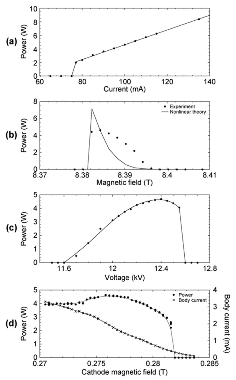
CW output power in the TE0,6 second harmonic mode as a function of (a) beam current, (b) main magnetic field, (c) voltage, and (d) cathode magnetic field. Magnetic tuning (b) is compared with nonlinear theory from MAGY simulations, and in (a), (c), and (d), the lines are added as a guide.
In Fig. 3(b), the experimentally measured continuous duty power of the design TE0,6,1 mode with varying magnetic field is compared with the theoretical results from MAGY, a self-consistent nonlinear code developed by the University of Maryland, College Park, and the Naval Research Laboratory, Washington, DC [8]. In the theoretical model, we assumed 30% losses in the quasi-optical mode converter. A conductivity one-fifth that of ideal copper is used based on cavity thermal load measurements of the second harmonic TE0,6,1 mode. The following parameters of the electron gun operation were obtained through EGUN simulations: the guiding center spread is 5.5%, the transverse velocity spread is 6%, and the pitch factor is 2.4 [5]. At beam parameters of 100 mA and 12.4 kV, a power of nearly 5 W is recorded. However, the theory shows a slightly elevated power of 7 W indicating that either the mode converter is less efficient than previously assumed or that the beam quality is below that which is expected. There is no present explanation for the difference in width of the theoretical and experimental curves.
The power was optimized as a function of beam voltage [Fig. 3(c)], yielding an optimum beam voltage of 12.4 kV. In our diode electron gun, the electron velocity pitch factor changes rapidly with cathode magnetic field, along with other factors such as main magnetic field and cathode voltage [5]. This rapid change is illustrated in Fig. 4. A first-order attempt at holding the alpha (ratio of transverse to longitudinal velocity of the electrons) constant was made in the voltage optimization measurement by maintaining a constant body current signal. The small but nonzero body current is attributed to reflected electrons originating from an unusually high alpha, and is less than 2% of the total beam current in most cases. Since we do not have an alpha probe in our experiment, an experimental illustration of the change in alpha with cathode magnetic field can be inferred from the change in body current and is shown in Fig. 3(d). Here, both the power and body current are shown as a function of changing cathode magnetic field. The body current increases from zero to four milliamperes with decreasing cathode magnetic field (increasing alpha) while the power increases with decreasing cathode magnetic field (increasing alpha and increasing beam compression) until a point where the overall beam quality suffers.
Fig. 4.

EGUN simulations for varying cathode magnetic fields at 12.4 kV and 100 mA.
C. Frequency Pulling
The dependence of the emission frequency on the operating parameters is an important metric of the frequency stability of the gyrotron. The DNP application requires approximately 5 MHz frequency stability near 460 GHz (corresponding to 700 MHz iH). While the gyrotron frequency at the nominal operating parameters is 458.56 GHz, in the present paper it is referred to as either 459 GHz or “near 460 GHz.” The dependence of the emission frequency of the TE0,6 design mode on the operating parameters such as the beam current, main magnetic field, beam voltage, and cathode magnetic field was characterized using a heterodyne frequency system. The heterodyne receiver system is highly accurate due to a phased locked loop which is capable of stabilizing the local oscillator to 1 Hz (Phase Matrix EIP 578B). Only a single parameter was varied for each measurement in order to simulate operation. While the beam voltage is not likely to change during operation, the control of the output power feedback will cause the beam current to vary in response to fluctuations in the output power. While in persistent mode, the main magnetic field will drift downward at a specified rate (ppm/hour) over long periods of time and the cathode magnetic field may vary due to heating of the gun coil.
The measured frequency pulling characteristics of the gyrotron are plotted in Fig. 5 and the frequency dependence on operating parameters is summarized in Table II. The total frequency change observed is within 30 MHz. Linear theory predicts that the pulling effects on frequency by the magnetic field are proportional to ω/Q [9].
Fig. 5.

Frequency tuning of the TE0,6 second harmonic mode with (a) beam current, (b) main magnetic field, (c) voltage, and (d) cathode magnetic field. Magnetic frequency tuning (b) is compared with nonlinear theory from MAGY simulations, and in (a), (c), and (d), the lines are added as a guide.
TABLE II.
Frequency Dependence on Operating Parameters
| Parameter | Sensitivity |
|---|---|
| Beam current | 0.4 MHz/mA |
| Magnetic field | 3.0 GHz/T |
| Beam voltage | 50 MHz/kV |
| Cathode magnetic field | 1.3 GHz/T |
The frequency pulling effects of the cathode voltage Vc and main magnetic field B in Fig. 5(b) and (c) have opposing slopes. For a given beam current, the observed shift in emission frequency resulting from changes of either the main magnetic field or the beam voltage is due to the effect on the cyclotron frequency, ωc(=eB/γme), where γ (= 1 + Vc/511) is the relativistic factor, and the cathode voltage Vc is in kilo volts. If the magnetic field alone is varied, the resulting frequency pulling will have a positive slope, and if the voltage is varied, the frequency pulling will have a negative slope. However, in theory over small values, coordinated changes in both the magnetic field and cathode voltage may leave the cyclotron frequency unchanged such that there is no change in the emission frequency. The same nonlinear theory (MAGY) as was used to simulate the power as a function of magnetic field yields results for the frequency pulling, which are compared with experimental data in Fig. 5(b) with coinciding slope.
D. Ohmic Losses
At high frequencies, a significant portion of the power generated in the cavity is not extracted and is instead deposited in the cavity walls in the form of ohmic heating. These ohmic losses are given by the ratio of diffractive to ohmic Q multiplied by the output power
| (1) |
where
| (2) |
| (3) |
The method, materials, and process of fabrication of the cavity are the main contributions to the experimental value of the ohmic losses. For example, the properties of the material (in our case copper), in particular the electrical conductivity and surface roughness, as well as machining anomalies such as irises, in essence determine the ohmic losses. The theoretical radio-frequency (RF) efficiency, diffractive Q, and conductivity for the second harmonic TE0,6,1 mode are given in Table III. The RF efficiency is the fraction of output power with respect to the total power generated in the cavity. With an initial value near 40% at the conductivity of ideal copper (5.8 × 10⁷ S/m), the RF efficiency rapidly decreases as the quality of copper degrades. By contrast, the RF efficiency decreases rapidly with increasing diffractive Q.
TABLE III.
Design and Measured Parameters From the Ohmic Loss Measurement of the Gyrotron Cavity at 458.6 GHZ
| Design | Measured | |
|---|---|---|
| Conductivity ×(5.8× 10⁷ S/m) | 0.5 | 0.25 |
| Diffractive Q | 31,000 | 47,000 |
| RF efficiency (%) | 32 | 24 |
A measurement of the ohmic losses in the TE0,6 second harmonic design mode of the 460-GHz gyrotron was made possible by the data acquisition capabilities of the computerized control system. By measuring the flow rate and change in temperature of the cavity cooling water, the amount of power transferred from the cavity to the water could be calculated. The temperature of the cavity cooling water was simultaneously measured at both the inlet and outlet of the cavity with separate thermistors, where the measurement was taken as spatially close to the cavity as possible to prevent heat transfer between the cooling hose and the ambient. Assuming that the water is in good thermal contact with the cavity and that the cavity is thermally isolated from any other source of heat internal or external to the tube (such as the collector which is isolated by a ceramic insulator), this is equivalent to measuring the thermal load on the cavity. A period of up to several minutes was allowed for thermal equilibrium to be reached.
Using wet calorimetry, the ohmic power distribution was measured for CW gyrotron output powers up to 4 W. The output microwave power was measured using dry calorimetry. The results of these measurements are shown in Table IV. The RF efficiency is nearly constant with output power and the cavity thermal load is linear with output power. The observed RF efficiency of 24% is approximately 8% less than the theoretical value. The effective electrical conductivity required to match the experimental results ranges between one-quarter and one-fifth that of ideal copper. An increase in the cavity diffractive Q from 31000 to 47000 might also explain the increased cavity losses, and this might result from errors in the manufacture of the shallow output taper. The design and measured values for the ohmic loss measurement are summarized in Table III. The measured quantities are given such that the value reflects a single parameter change in either electrical conductivity or diffractive Q. Both the increase in diffractive Q and decrease in conductivity are within reasonable bounds and in reality it is probably a combination of the two factors contributing to the slightly elevated ohmic losses.
TABLE IV.
Measured and Theoretical Ohmic Losses in the Gyrotron Cavity at 458.6 GHZ
| Output power (W) | Cavity thermal load (W) | RF efficiency (%) |
|---|---|---|
| 0 | 0 | - |
| 2.5 | 7.9 | 24.0 |
| 3.75 | 12.1 | 23.6 |
| 4.1 | 13.5 | 23.3 |
E. Spectral Purity
The radiation produced by the gyrotron has a finite linewidth which can be attributed to both intrinsic (natural) and extrinsic (technical) sources. The fluctuations of the technical parameters which dominate over the natural noise sources cause the broadening of the radiation linewidth in gyrotrons [10], [11]. Among these technical or operating parameters are the beam voltage, beam current, and external magnetic field.
The 460-GHz time domain signal is an amplitude modulated (AM) signal which can be demodulated yielding both the linewidth and technical noise of the device. An overmoded horn directed at the gyrotron output beam coupled a sample of the gyrotron radiation into the homodyne receiver. In our case, the main center line frequency of the gyrotron acts as a local oscillator; this frequency beats with any other frequencies that are generated by the gyrotron in the harmonic mixer, including those generated by spurious or competing gyrotron modes. The receiver consists of a mixer followed by three intermediate frequency (IF) amplifiers whose amplification bandwidth is from approximately 0.1–1000 MHz, and a low pass filter with 520 MHz cutoff frequency. Thus, the intermediate frequencies between 0.1 and 520-MHz are amplified, digitized, and passed through an FFT.
The results of homodyne measurements on the TE0,6,1 mode over 1-, 25-, and 500-MHz bands are shown in Fig. 6. Since the amplifiers do not pass dc, these signals are presumed to be well below the gyrotron center line frequency. The technical noise in the gyrotron is apparent in the tens of kilohertz (cf. Fig. 6). The high-voltage power supply is a likely source of the noise in this band. The specifications for the ripple on the power supply are 0.03% root mean square (rms) below 1 kHz and 0.75% rms above 1 kHz. In addition, the alternating current filament output is at 38 kHz. The gyrotron signal at higher frequencies shows little contamination [cf. Fig. 6(c)] indicating single mode operation.
Fig. 6.

Homodyne measurements of the technical noise for the second harmonic TE0,6,1 mode.
F. Radiation Patterns
The first element in the quasi-optical transmission line is the quasi-optical antenna located internal to the gyrotron and collinear to the cross-bore of the superconducting magnet. Its function is to efficiently convert the operating TE0,6 waveguide mode into a free-space Gaussian beam which will then be transmitted out of the vacuum tube to the DNP probe through a transmission line. That line can be either a corrugated metallic or hollow dielectric waveguide supporting the HE1,1 quasi-Gaussian mode or a mirror line supporting the free-space Gaussian mode. This experiment employs an internal quasi-optical mode converter to efficiently separate the microwave beam from the energetic electron beam; the microwave beam is directed to the experiment through an orthogonal cross bore in the superconducting magnet, while the electron beam is collected in a compact, water-cooled collector region, far from any fragile microwave structures or windows. This in turn increases the vacuum pumping conductance and reduces the ohmic losses in the output waveguide. The mode converter consists of a cylindrical waveguide with a step cut and a cylindrical focusing mirror. The waveguide antenna converts the higher order transverse electric gyrotron output into a linearly polarized beam which is subsequently collimated by the focusing mirror. The mode converter works well for TEm,p modes where m ≪ p.
A pyroelectric camera laser beam diagnostic system developed by Spiricon, Inc. (Pyrocam III) was used for millimeter and submillimeter-wave radiation pattern measurements. The camera is a pyroelectric array consisting of 124 by 124 elements where the element spacing is 100 by 100 μm, yielding an active area of 12.4 by 12.4 mm. The pyroelectric camera has been previously used to image the output beams of 250-GHz [12] and 140-GHz [13] gyrotrons. During these measurements, the gyrotron was operated in CW mode with an output power of less than 2 W. Since a pyroelectric detector is sensitive only to alternating signals, the CW gyrotron beam was modulated at 48 Hz by an optical chopper housed in the body of the camera. Since the gyrotron window is 25.4 mm in diameter and set inside the cross bore of the superconducting magnet, an epoxyglass waveguide (supporting the HE1,1 mode) with 25.4 mm inner diameter conveyed the output power to the pyroelectric camera over a distance of 66 cm. As a result, the detector aperture does not cover the entire area of the waveguide. The detector gain was set near the threshold of saturation to maximize the dynamic range of the measurement. Data were processed by subtraction of a separately recorded dark frame to eliminate systematic dead pixel artifacts and background noise, followed by averaging of 128 captured frames to improve the sensitivity of the measurement.
An image of the captured TE0,6 mode-converted beam at 459 GHz is displayed in Fig. 7(a). A Gaussian fit [cf. Fig. 7(b)] determined that the measured beam is slightly elliptical with a waist size in y of 4.91 ± 0.04 mm and a waist size in x of 4.67 ± 0.04 mm, where the beam waist is given by 1/e2 from the maximum intensity or −8.7 dB. The 4% ellipticity indicates a good performance of the internal quasi-optical mode converter. The output field patterns of the converted TE0,6, TE2,6, TE2,3, and TE2,2 modes were also measured (cf. Fig. 8). These modes span 157 through 459 GHz demonstrating that the pyroelectric camera functions continuously from millimeter to submillimeter wavelengths. The quasi-optical mode converter will convert most TEmp modes to free-space Gaussian beams where m ≪ p. In agreement with this prediction, images of the gyrotron operating in the TE0,6 and TE2,6 show a Gaussian beam, while images with the gyrotron operating in the TE2,3 and TE2,2 modes do not. Table V shows the beam waists of the four modes as calculated by a best fit Gaussian with 95% confidence interval. A rectangular grid diffraction pattern is observed on the high frequency intensity patterns that is not observed on the lowest frequency intensity pattern. The spacing of the elements in the pyroelectric array is 100 μm, which may cause interference effects with the gyrotron wavelengths in the hundreds of microns.
Fig. 7.

Planar section of the 460-GHz radiation intensity as recorded by a pyroelectric camera. (a) is the intensity 66 cm along the waveguide axis, (b) is a Gaussian fit of the intensity data, and (c) is the residual of the fit. Intensity is described on a linear scale in arbitrary units.
Fig. 8.

Linear radiation intensity patterns of the mode-converted (a) TE0,6, (b) TE2,6, (c) TE2,3, and (d) TE2,2 modes captured by a pyroelectric camera.
TABLE V.
Beam Waists of the Mode Converted Radiation Fields From Fig. 8 as Calculated by the Best Fit Gaussian
| TEm,p mode | Frequency (GHz) | x waist (mm) | y waist (mm) | Ellipticity (%) |
|---|---|---|---|---|
| TE0,6 | 459 | 4.67 ±0.04 | 4.91 ±0.04 | 4 |
| TE2,6 | 456 | 6.42 ±0.03 | 5.63 ±0.02 | 12 |
| TE2,3 | 233 | 5.25 ±0.02 | 6.60 ±0.02 | 20 |
| TE2,2 | 157 | 3.00 ± 0.02 | 3.81 ±0.02 | 21 |
G. CW Stability
Operating under a computerized control system, the 460-GHz gyrotron is capable of stable CW emission for extended periods. The control system, implemented in the Lab VIEW software package, is based upon similar principles as a computerized control system written for a low power CW 250-GHz gyrotron which has operated continuously for over 21 days and has been in service for seven years [12]. The stability of the emission in the TE0,6,1 second harmonic mode near 460 GHz and, separately, the TE2,3,1 fundamental mode near 230 GHz was monitored for a period of 1 h during which the gyrotron ran in complete CW mode. During this period, a constant output power was maintained by proportional, integral, and derivative feedback adjustments to the filament current based on the difference between the set point and monitored power signal. The output power was monitored in two cases, first with a diode and later with a calorimeter. In the case of diode monitoring, the output power was referenced at the start and finish of the monitoring period with the calorimeter. All aspects of the experiment were monitored by the computerized control system and logged, including the output power, pressure, beam voltage, beam current, filament current, and gun coil current. The superconducting magnet was in persistent mode.
A summary of the TE0,6,1 second harmonic and TE2,3,1 fundamental results is shown in Fig. 9 and Table VI. A statistical analysis of excursions of the 459-GHz power signal from its set point over the hour long experiment using a diode for feedback (Fig. 10) shows that power fluctuations are normally distributed and that the tolerances of the DNP experiment are met by the control system. Notably, the power was stable to within 1% for all cases over the hour long period using feedback from either a diode or calorimeter, where the dotted lines in Fig. 9 represent ± 1 % of the power signal. The pressure in all cases was low, but showed a tendency to increase for second harmonic operation. This increase in pressure was directly related to the increase in beam current required to maintain the constant output power.
Fig. 9.

Three separate one-hour duration stability tests of the (a) power, (b) pressure, (c) beam voltage, (d) filament current, (e) beam current, and (f) gun coil current for the TE0,6,1 second harmonic mode at 459 GHz using a diode (left) and calorimeter (center) and for the TE2,3,1 fundamental mode at 233 GHz using a diode (right) to monitor the output power. Dotted lines on (a) represent 1 % stability.
TABLE VI.
Stability of the Second Harmonic TE0,6,1 and Fundamental TE2,3,1 Modes in the 460-GHZ Gyrotron
| TE0,6,1 (diode) | TE0,6,1 (calorimeter) | TE2,3,1 (diode) | ||||
|---|---|---|---|---|---|---|
| Avg. | Std. dev. % | Avg. | Std. dev. % | Avg. | Std. dev. % | |
| Power (W) | 3.76 | 0.3 | 3.13 | 0.4 | 4.69 | 0.2 |
| Pressure (×10−8 Torr) | 4.34 | 3.4 | 3.80 | 1.7 | 1.21 | 1.7 |
| Beam voltage (kV) | 12.40 | 0.0 | 12.40 | 0.0 | 3.50 | 0.0 |
| Filament current (A) | 2.55 | 1.0 | 2.52 | 0.6 | 2.36 | 0.3 |
| *Beam current (mA) | 119.0 | 8.6 | 111.1 | 6.1 | 19.7 | 2.7 |
| Gun coil current (A) | 2.54 | 0.0 | 2.54 | 0.1 | 24.63 | 0.0 |
Beam current was monotonically increasing in the second harmonic experiment.
Fig. 10.

Statistical analysis of power fluctuations from set point for the diode controlled TE0,6,1 one-hour-long run. Solid line is a Gaussian fit to the data.
In both the fundamental and second harmonic operation, the output power is regulated through changes in the filament current, which, in turn, brings about proportional changes in the beam current. During constant power operation in the fundamental mode, however, the beam current and filament current change much less than they do for similar operation at the second harmonic. While the RF output powers were comparable for both the fundamental and second harmonic controlled runs, their beam powers differed by a factor of 20 due to the difference in efficiency; where a beam power of 70 W was used for the fundamental, 1.4 kW of beam power was used for the second harmonic. Experimental runs of the gyrotron indicate that the increase in beam current required to maintain a constant second harmonic output power is likely due to the overheating of the electron gun. An improvement of the electron gun cooling system will be implemented in future runs.
III. Conclusion
The 460-GHz experiment has successfully demonstrated that a gyrotron can efficiently produce over 8 W of average power at the second electron cyclotron harmonic in low voltage operation. To our knowledge, this is the highest CW output achieved by a gyrotron this far into the submillimeter wavelength band. The efficiency of the gyrotron was verified with measurements of the cavity ohmic losses which also confirmed the ratio of diffractive to ohmic Q. The stability characteristics were studied over the duration of 1 h, and demonstrated that the output power could be maintained stable to within 1 % under computer control. The limiting factor in operating at longer periods of time is likely the overheating of the electron gun. This will be corrected in future operation. Frequency pulling measurements determined that the stability of the frequency with respect to the beam voltage, beam current, and magnetic field drift was sufficient for DNP. The radiation pattern of the second harmonic design mode at 460 GHz shows that the beam is Gaussian with a 4% ellipticity and that the mode converter works reasonably well for several other observed second harmonic and fundamental modes. In addition, the gyrotron operates at useful CW output powers in several fundamental modes for which the design was not explicitly optimized; many of these modes also exhibit unusually broad magnetic tunability. The 460-GHz gyrotron will serve as a millimeter-wave source for sensitivity-enhanced nuclear magnetic resonance (dynamic nuclear polarization) experiments at a magnetic field of 16.4 T (700 MHz 1H), which will be the highest frequency DNP experiments attempted to date.
Acknowledgments
The authors would like to thank A. Fliflet, S. Gold, C. Joye, K. Kreischer, D. Lewis III, I. Mastovsky, N. Pereira, M. Shapiro, J. Sirigiri, P. Woskov, and A. Barnes.
Biographies
Melissa K. Hornstein (S’97-M’05) received the B.S. degree in electrical and computer engineering from Rutgers University, New Brunswick, NJ, in 1999, and the M.S. and Ph.D. degrees in electrical engineering and computer science from the Massachusetts Institute of Technology (MIT), Cambridge, MA, in 2001, and 2005, respectively.
From 2000 to 2005, she was a Research Assistant at the MIT Plasma Science and Fusion Center and the Francis Bitter Magnet Laboratory. She was involved in the design, development, testing, and analysis of a novel submillimeter wave second harmonic gyrotron oscillator, as well as other projects in the millimeter and submillimeter regime. Since 2005, she has been at the Naval Research Laboratory as an Nuclear Regulatory Commission (NRC) Postdoc in the Plasma Physics Division. Her research interests include terahertz sources and their applications, such as enhanced nuclear magnetic resonance spectroscopy via dynamic nuclear polarization.
Vikram S. Bajaj received the B.A. degree in biochemistry and the M.S. degree in chemistry concurrently from the University of Pennsylvania, Philadelphia, PA, in 2000. He is currently working toward the Ph.D. degree in the Department of Chemistry (Physical Chemistry Division), Massachusetts Institute of Technology (MIT), Cambridge, MA.
Since 2000, he has been a Research Fellow at the MIT Francis Bitter Magnet Laboratory, where his work involves structure determination of biomolecules through solid state nuclear magnetic resonance (NMR) and the development of dynamic nuclear polarization (DNP) for sensitivity enhancement in NMR spectroscopy.
Robert G. Griffin received the B.S. degree in chemistry from the University of Arkansas, Fayetteville, in 1964 and the Ph.D. degree in physical chemistry from Washington University, St. Louis, MO, in 1969. He did his postdoctoral research in physical chemistry at the Massachusetts Institute of Technology (MIT), Cambridge, with Prof. J. S. Waugh.
In 1972, after completing his postdoctoral training, he assumed a staff position at the Francis Bitter National Magnet Laboratory (FBML), MIT. In 1984, he was promoted to Senior Research Scientist, and was appointed to the faculty in the Department of Chemistry, MIT, in 1989. In 1992, he became Director of the FBML and is concurrently Director of the MIT-Harvard Center for Magnetic Resonance, where he had been Associate Director since 1989. He has published more than 300 articles concerned with magnetic resonance methodology and applications of magnetic resonance (NMR and EPR) to studies of the structure and function of a variety of chemical, physical and biological systems. In the last decade, this research has focused on the development of methods to perform structural studies of membrane and amyloid proteins and on the utilization of high-frequency (> 100 GHz) microwaves in EPR experiments and in the development of DNP/NMR experiments at these frequencies. He has served on numerous advisory and review panels for the National Science Foundation and the National Institutes of Health.

Richard J. Temkin (M’87-F’94) received the B.A. degree in physics from Harvard College, Cambridge, MA, and the Ph.D. degree in physics from the Massachusetts Institute of Technology (MIT), Cambridge.
From 1971 to 1974, he was a Postdoctoral Research Fellow in the Division of Engineering and Applied Physics, Harvard University. Since 1974, he has been with MIT, first at the Francis Bitter National Magnet Laboratory and later at the Plasma Science and Fusion Center (PSFC) and the Department of Physics. He currently serves as a Senior Scientist in the Physics Department, as Associate Director of the PSFC, and Head of the Waves and Beams Division, PSFC. His research interests include novel vacuum electron devices such as the gyrotron and free electron laser, advanced, high-gradient electron accelerators, quasi-optical waveguides and antennas at millimeter wavelengths, plasma heating, and electron spin resonance spectroscopy. He has been the author or coauthor of over 200 published journal articles and book chapters and has been the editor of six books and conference proceedings..
Dr. Temkin is a Fellow of the American Physical Society and The Institute of Physics, London, U.K. He has been the recipient of the Kenneth J. Button Prize and Medal of The Institute of Physics, London and the Robert L. Woods Award of the Department of Defense for Excellence in Vacuum Electronics research.

Footnotes
This work was supported by the National Institutes of Health under Grant EB002061, Grant EB002804, and Grant EB002026. The work of V. S. Bajaj was supported by an NSERC PGS Fellowship.
References
- 1.Hong K, Brand G, Idehara T. A 150–600 GHz step-tunable gyrotron. J Appl Phys. 1993 Oct;74(8):5250–5258. [Google Scholar]
- 2.Idehara T, Yoshida K, Nishida N, Ogawa I, Pereyaslavets ML, Tatsukawa T. Int J Infrared Millim Waves. 6. Vol. 19. Jun, 1998. CW operation of a submillimeter wave gyrotron (gyrotron FUIV) for high stability of the output frequency; pp. 793–801. [Google Scholar]
- 3.Zaytsev N, Pankratova T, Petelin M, Flyagin V. Millimeter- and submillimeter-wave gyrotrons. Radio Eng Electron Phys (USA) 1974 May;19(5):103–107. [Google Scholar]
- 4.Flyagin V, Luchinin A, Nusinovich G. Submillimeter-wave gyrotrons: theory and experiment. Int J Infrared Millim Waves. 1983 July;4(4):629–637. [Google Scholar]
- 5.Hornstein MK, Bajaj VS, Griffin RG, Kreischer KE, Mastovsky I, Shapiro MA, Sirigiri JR, Temkin RJ. Second harmonic operation at 460 GHz and broadband continuous frequency tuning of a gyrotron oscillator. IEEE Trans Electron Devices. 2005 May;52(5):798–807. [Google Scholar]
- 6.Kreischer K, Farrar C, Griffin R, Temkin R, Vieregg J. A 250 GHz gyrotron for NMR spectroscopy. 27th IEEE ICOPS Record Abstracts; New Orleans, LA. Jun. 2000; p. 198. [Google Scholar]
- 7.Bajaj V, Farrar C, Homstein M, Mastovsky I, Vieregg J, Bryant J, Elena B, Kreischer K, Temkin R, Griffin R. Dynamic nuclear polarization at 9 Tesla using a novel 250 GHz gyrotron microwave source. J Mag Res. 2002 Feb;160(2):85–90. [Google Scholar]
- 8.Botton M, Antonsen T, Levush B, Nguyen K, Vlasov A. MAGY: A time-dependent code for simulation of slow and fast microwave sources. IEEE Trans Plasma Sci. 1998 Jun;26(3):882–892. [Google Scholar]
- 9.Kreischer K, Danly B, Woskoboinikow P, Mulligan W, Temkin R. Frequency pulling and bandwidth measurements of a 140 GHz pulsed gyrotron. Int J Elec. 1984 Dec;57(6):851–862. [Google Scholar]
- 10.Dumbrajs O, Nusinovich G. Effect of technical noise on radiation linewidth in free-running gyrotron oscillators. Phys Plasmas. 1997 May;4(5):1413–1423. [Google Scholar]
- 11.Nusinovich G, Dumbrajs O. Technical noise in gyroklystrons and phase-locked gyrotron oscillators. Phys Plasmas. 1997 May;4(5):1424–1433. [Google Scholar]
- 12.Bajaj VS, Hornstein MK, Kreischer KE, Woskov PP, Mak ML, Herzfeld J, Temkin RJ, Griffin RG. A continuous duty cycle 250 GHz gyrotron oscillator for dynamic nuclear polarization in biological solid state NMR. J Mag Res. 2006 doi: 10.1016/j.jmr.2007.09.013. [DOI] [PMC free article] [PubMed] [Google Scholar]
- 13.Joye C, Griffin R, Hornstein M, Hu K, Kreischer K, Rosay M, Shapiro M, Sirigiri J, Temkin R, Woskov P. Operational characteristics of a 14-W 140-GHz gyrotron for dynamic nuclear polarization. IEEE Trans Plasma Sci. 2006 Jun;34(3):518–523. doi: 10.1109/TPS.2006.875776. [DOI] [PMC free article] [PubMed] [Google Scholar]