Abstract
This paper presents a new approach dealing with virtual exploratory navigation inside vascular structures. It is based on the notion of active vision in which only visual perception drives the motion of the virtual angioscope. The proposed fly-through approach does not require a pre-modeling of the volume dataset or an interactive control of the virtual sensor during the fly-through. Active navigation combines the on-line computation of the scene view and its analysis, to automatically define the 3D sensor path. The navigation environment and the camera-like model are first sketched. The basic stages of the active navigation framework are then described: the virtual image computation (based on ray casting), the scene analysis process (using depth map), the navigation strategy and the virtual path estimation. Experimental results obtained from phantom model and patient CT-data are finally reported.
Keywords: Algorithms; Angiography; methods; Angioscopy; methods; Humans; Pattern Recognition, Automated; methods; Radiographic Image Enhancement; methods; Radiographic Image Interpretation, Computer-Assisted; methods; Reproducibility of Results; Sensitivity and Specificity; Surgery, Computer-Assisted; methods; User-Computer Interface
Keywords: virtual angioscopy, active virtual sensor, automatic path planning
I. INTRODUCTION
The recent advances in medical imaging (e.g. high resolution patient data), the availability of methods for image analysis and computer graphics, the technological resources provided by micro-devices and the design of minimal access surgical procedures have opened the road to new concepts. Virtual endoscopy represents one of these areas and points out the applicative potential of three dimensional (3D) imaging. It leads to less invasive diagnosis and therapeutic achievements, and addresses important issues in computer aided diagnosis, interventional planning, and medical education.
Volumes provided by CT or MRI allow the user to move virtually within the anatomical structures. Different approaches addressing various clinical applications, such as virtual colonoscopy [1]–[7], virtual bronchoscopy [8]–[12], virtual angioscopy [13]–[19] and others, have been proposed in the literature. Most of them assume that a pre-computed model (organ inner surface, sensor path) of the anatomical structures to be explored virtually is available. Beyond the interactive observation of hollow organs, they are now dealing with the problems of precomputing a central path and automatic path planning [20]–[23], controlling the position and orientation of the virtual camera to fully examine the interior organ surface [24] [25], quantitative analysis of the observed lesions [26], fusion of multi-modality information [27], simulation of the physical properties of the endoscope [28], matching virtual and real endoscope views [29] [30], and evaluation and clinical validation [2] [31]. Although these problems are generic, their difficulty can vary, according to the explored organ, whose size, geometry, topology, arrangement in the numerical dataset and pathology are subject to significant disparities.
We investigate a new approach which aims to explore automatically vascular structures using virtual angioscopy. Conventional fly-through approaches require a centerline which is used as the virtual angioscopy path. It may be calculated off-line or on-line. The off-line computation of the centerline in tubular objects requires the preprocessing of the volumetric dataset by skeletonization and segmentation algorithms using region growing [32], multi-scale filtering [33], or deformable models [34] [35]. The on-line extraction of the centerline was recently investigated by locally analyzing volumetric data within a plane shifted perpendicularly to the tracked centerline [36] [37] or with 3D geometrical moments [38]. These approaches, and more generally virtual path determination approaches, have still to face some difficulties. Due to the detection problems (low contrast, noisy data), the free-form shape of the structures (tortuousity), the presence of different types of lesions (thrombus, calcified plaques), the possible branching of the cavities (leading to multiple candidate paths), automatic path planning is a challenging issue in virtual angioscopy. Moreover, it is generally performed prior to the visualization process which constitutes one of the primary functions of virtual angioscopy and may provide meaningful information.
This paper focuses on scene analysis and automatic path planning. The proposed method is based on the “active sensor” notion and can be related to vision guided navigation for mobile robots. Active navigation combines the online computation of the scene view and its analysis, to automatically define the 3D virtual path and the structural description of the unknown environment explored. No pre-modeling of the anatomical structures is used: surface detection, computation of optical-like virtual images, scene analysis, and path estimation are performed throughout the navigation. Thanks to a scene analysis process, short range to long range visions are also available. The former provides the information about the immediate surroundings (walls or obstacle) and determines the displacement of the sensor and the potential for collision. The latter gives useful indications about the target area to be reached.
The general framework of this study, whose basic functions have already been reported in the literature [39], [40], is summarized in Section II. Section III presents a complete description of the scene analysis process, going from the computation of feature points to the generation of a graph showing the topology of the observed structures. In order to plan the virtual sensor path, a navigation strategy based on the use of the information derived from the scene analysis is proposed in Section IV. The effectiveness of our approach is highlighted in Section V by its application to several experimental datasets acquired by helical CT-scan modality under clinical conditions, and then discussed in Section VI.
II. VIRTUAL EXPLORATORY NAVIGATION: BASICS FOR ACTIVE NAVIGATION
An overview of the functions involved in active navigation is given in Fig. 1. The main functionalities a virtual endoscope device should provide are: image computation and display, scene analysis, path estimation, collision avoidance, and operator controllability. Different loops can then be identified to automate the navigation: they deal with the motion of the sensor to be applied, according to the detection or not of a collision, and, in case of multiple cavities, the storage of candidate paths.
Fig. 1.
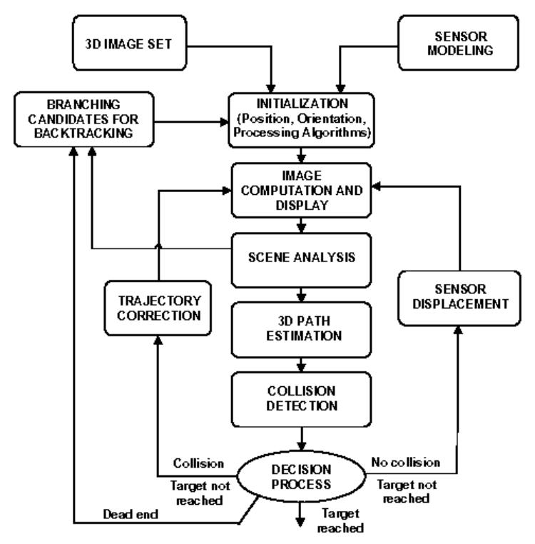
Overall flowchart of the active navigation.
The geometric model of the virtual camera introduced in the discrete volume is based on a classical perspective projection in which the focal length and the size of the imaging area determine the field of view. The rotations between the volume coordinate system and the local coordinate system attached to the virtual sensor are expressed in terms of Euler / Cardan angles. Yaw and pitch rotations are used to describe the virtual camera orientation. Roll rotation around the viewing axis is fixed at zero degree. Given a 3D image, the first task consists in interactively setting the virtual sensor parameters, which include its initial pose (position and orientation) within the volume and its field of view (FOV). These geometrical parameters must be completed by specifying the 3D discrete array resolution and the detection algorithm parameters. From this point on, two operational modes can be applied: (i) the semi-interactive mode, where some commands are entered interactively (stopping the navigation, deciding on the preferred path to track, …), and (ii) the fully automatic mode where a free (i.e. auto-constrained) navigation is carried out between an initial point and a target point, both defined by the user.
Virtual image computation is based on a ray casting technique integrating analysis functions. Several types of detection operators might be used [41, 42]. In this study we used a simple solution. Due to the large resolution difference between the local sensor image and the initial volume data (in the case of vascular structures notably), the trilinear interpolation of the voxel values and the surface normals is performed in order to avoid unrealistic discontinuities in the virtual image. Thus, a relatively good image quality can be obtained, even when considering small sized structures (1 mm of diameter), by seeking the transition surface between the contrast medium (or the cavity) and the vessel wall, with a coarse to fine progression rate along the ray. The surface point is found when the difference between the interpolated values at the origin and along the ray becomes higher than a user defined surface detection threshold.
Several solutions to path planning from the analysis of image sequences have been proposed in the computer vision literature [43]. They deal with problems of vision based-navigation for indoor and outdoor robots. In [44] a robot path planning approach [45] has been adapted to automatic path planning in virtual endoscopy. Concerning path generation for autonomous robot navigation in natural environments, one can generally distinguish reactive techniques based on local perception of the environment [46] [47], from planning based techniques which make use of a more global representation of the environment [48] [49]. Since the virtual image computation provides a set of cavity surface points whose coordinates are known within the camera reference system and also within the global frame of the volume image, the proposed method consists in reducing the problem to only one information: the depth map. Thus, this approach can be qualified as Map-Building-Based navigation. A number of studies dealing with depth map segmentation have already been carried out. Among them, one can mention: plane fitting and clustering [50], [51], iterative labeling of objects by means of Gaussian curvatures [52], or surface primitives (such as spheres and cylinders) fitting [53]. It must be emphasized that the environments we are dealing with are poorly featured when compared to indoor or outdoor environments. They cannot be described by means of simple primitives such as straight lines, corners or planes.
Assuming the piecewise linear approximation of the path, collision (an object must not pass through another) has to be examined. Based on the collision detection and the correction of its position, the camera-like sensor can be displaced and re-oriented. The last feedback implies the activation of a more complex decision process to choose the cavity to be explored when multiple candidates are detected. A backtracking procedure can be activated if the user-defined target is not reached (wrong previous path), as well as if the termination of a branch has been reached for instance. In the following sections we focus on the scene analysis and path planning process.
III. SCENE ANALYSIS
In our approach, the scene analysis process is based on the progressive construction of a global structure describing the hollow organ observed. At the local level (for each position of the sensor), a tree like representation is derived from the depth map processing. A node is given by a point featuring the frontier between different branches (border points), and a leaf corresponds to the maximum depth in a branch.
A. Depth map analysis
Thanks to the ray casting algorithm, the image computation process directly provides the distance between each detected surface point and the optical center of the virtual camera. This depth information can be coded by an image the same size as the virtual image (Fig. 2(a)–(c)). In this depth map, noted , the possible branches are associated to light gray regions. Thus, can be processed as a gray level image to detect local maxima, to select the relevant ones characterizing the branches and to detect points separating the branches in the bifurcation areas (border points).
Fig 2.
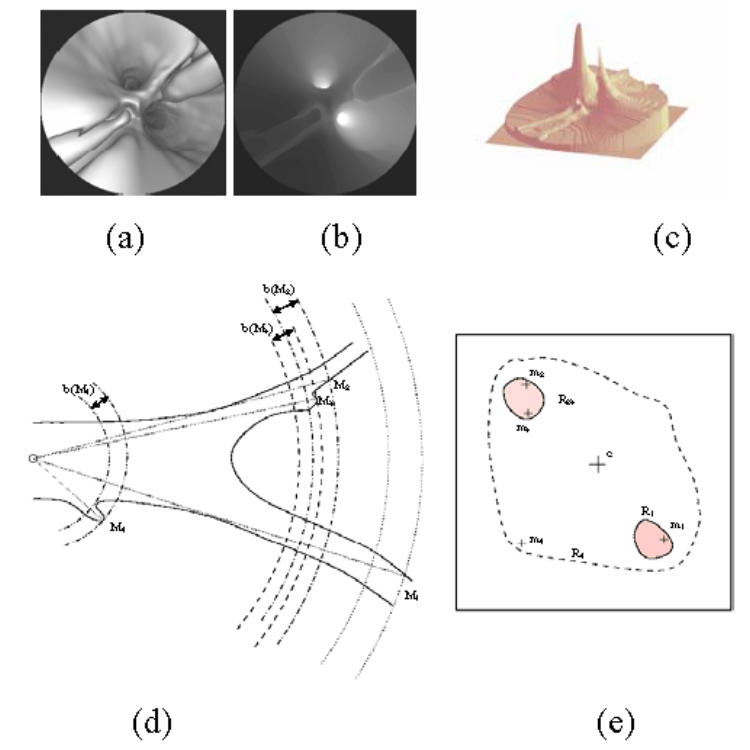
A typical depth map encountered in vascular structures: (a) the virtual endoscopy image, (b) the 2D gray level image of the depth and, (c) the 2.5D representation of the depth map. (d) An illustration of the detection of the depth maxima in a vascular bifurcation observed through a perspective geometry based virtual endoscope (Mi: 3D surface point corresponding to a depth maximum) and (e) the binarized depth map (mi: 2D projection of Mi on the image plane).
1) Detection of the depth maxima
A non linear filtering of the depth map is performed by imposing equality/inequality constraints which a depth maximum has to satisfy in relation to its neighbors. The maxima detection filters are defined as follows:
| (1) |
A good compromise between over- and under-detection is reached by using a filter. If no maximum is detected (or if the number of detected maxima is superior to the predefined depth selectivity parameter Nmax), the filtering is performed with (respectively with more selective filters to ). The set S of local depth maxima mi (associated with 3D surface points Mi) can then be reduced by considering a distance criterion. If two depth maxima are sufficiently close together (< dmax), the smallest maximum is removed from S. For all the experiments presented in this paper, dmax was fixed at 10 pixels.
2) Labeling of the depth maxima
The objective of this step based on the segmentation of the binarized depth map is twofold: (i) to label the depth maxima according to the branch they belong to, and (ii) to characterize each branch by its deepest maximum. In order to point out the regions characterizing the branches, a binary map Bi is created for each depth maximum mi. The binarization threshold Th is determined from two parameters: the value of the current depth maximum mi considered in the list S, and the backward parameter, b, which defines the minimal height of the hills that can be separated in the depth map: . The backward parameter b is a sigmoid function of the depth which guaranties a fine separation of the branches close to the virtual sensor and limits the number of regions beyond the depth x0 of its inflection point.
| (2) |
The labeling process consists in attributing a binary code to each depth maximum according to the region it belongs to. The coding scheme enables the distinction between regions of different natures as well as the simple handling of inclusion relationships. The labeling process works as follows:
- Initialization of n to zero.
-
- For each depth maximum mi of S listed in decreasing order:
Binarization of the depth map with the threshold Th(mi).
Segmentation of the binary map by means of a classical region growing algorithm using mi as seed point.
-
Labeling of the depth maxima:
If the detected region does not contain already labeled maxima, labeling of the depth maxima of the region with the binary word Ln equal to 2n and incrementation of n.
If the detected region contains already labeled maxima, assignment of a binary word to the non labeled depth maxima, given by the logic OR operation between the binary words affected to the already labeled maxima.
For example, in Fig. 2(d)–(e) showing the binary map obtained when considering the depth maximum m2, the region R23 is segmented. The depth maximum m1 (deeper than m2) has been treated previously and labeled by L0. The region R23 corresponding to a single branch at the considered position of the virtual sensor – the backward parameter taking a high value –, the depth maxima m2 and m3 are coded by the binary word L1. When the depth maximum m4 is considered, a region R4, including the regions R1 and R23, is created. Except for m4, all the depth maxima included in this region have already been treated and labeled. In this case a compound label L10 equal to L0 + L1 (logic OR operation) is affected to the new depth maximum m4.
In order to characterize a branch, only the deepest maximum with a single label (code with a single bit to 1) is retained. It has been the first one to be labeled in the branch and it is called the feature maximum. For instance, the region R23 and the corresponding vascular branch are characterized by the maximum m2 with the label L1. At the end of this process the branching structure describing the scene observed by the virtual sensor is composed of the 3D coordinates of the virtual sensor, the 3D coordinates (M) and the labels (L) of the feature maxima.
3) Detection of the border points
The feature maxima characterize the farthest regions from the virtual sensor likely to correspond to branches. Nevertheless, the depth maxima behave as viewpoint dependent descriptors. The spatial variability of the depth maxima between successive images makes them insufficient to describe and to follow the topological changes in the observed scene. Complementary elements, the border points, that intrinsically feature the frontier between different branches are introduced.
A border point is a depth local minimum separating two branches (represented by feature maxima) in the depth map. Considering the feature maxima in order of decreasing depth, the border point detection process starts with the second maximum (if it exists) and is repeated iteratively for all the following feature maxima. The depth map is binarized according to a first threshold value Thmax which is the same used for the labeling process. For instance, if we consider that the feature maximum mi has been detected in the scene, the first threshold is defined by: Thmax(mi) = Th(mi) with and b′(mi) = b(mi).
According to the definition of the feature maxima, the depth maximum mi is the single one within a region Ri. By increasing iteratively the value of b′(mi) (of a step equal to b(mi)), and consequently decreasing the threshold Th(mi), the region Ri grows until it merges with another region R (Th(mi) = Thmin) which contains a feature maximum which has not yet been separated from mi by a border point. The sought border point is located necessarily at a depth between Thmin and Thmax. The values of Thmin and Thmax (respectively associated to the binary maps Fmin and Fmax illustrated on Fig. 3(a)–(b)) are then refined by a bisection procedure until δ = Thmax − Thmin becomes lower than a predefined value Δ. The limit value Δ is fixed to 0.1 voxel that corresponds to the resolution step for the detection of the 3D surface points. A search window W is defined adaptively by computing the two mass centers C and C′ respectively associated with the regions Ri and R in Fmax. The square window W is placed at the center of [CC′] and its size is defined by: lw = CC′/2. The border point B is then defined as the local depth minimum of Fmin – Fmax in the window W (Fig. 3(c)–(d)).
Fig. 3.
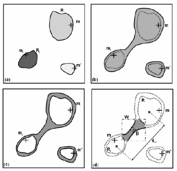
Seeking of the border point: (a) depth map binarized with Thmax (Fmax),(b) depth map binarized with Thmin (Fmin), (c) subtraction of the depth maps (Fmin-Fmax), (d) seeking of the depth minimum (border point) in the window W.
B. Structural description
At the local level, i.e. for a given position of the virtual sensor, a data structure can be derived from the feature points (feature maxima, border points) in order to define a structural description of the unknown scene. During the exploration of the anatomical structures, a global description is progressively constructed and updated by the local descriptions.
1) Local description
For each position of the virtual sensor, a structural description is constructed as a tree like structure. A node is given by a border point (featuring the frontier between different branches) and a leaf corresponds to the maximum depth in a branch. Each element of the binary tree is assigned with the 3D feature point (depth maximum or border point), the position and the orientation of the virtual sensor for which the feature point has been obtained, and the address of a possible child element.
The binary tree-like structures are relatively simple to handle and are well appropriate to the description of the anatomical structures that the virtual exploratory navigation is concerned with. A notable exception is encountered when the anatomical structure appears as a single tube-like shape where only one depth maximum is detected and no border point is defined. In this case the local description is reduced to a single element. It is said to be degenerated. The leaf is nonetheless retained within the description.
2) Global description
Different viewpoints along the virtual sensor trajectory lead to different local descriptions. Since border points are implicitly associated with geometrical features of the 3D scene, they are much less sensitive to viewpoint than the depth maxima. Border points are used to perform the matching of the successive local descriptions. Let and be the border points given respectively by the local descriptions di and di+1 at two positions Ci and Ci+1. matches if the following condition is verified: , where db is a heuristic parameter fixed at 10 voxels. The associated depth maxima (leaves of the tree) are also matched according to a distance criterion. In order to keep the longest branch in the global representation, a depth maximum is updated only when the new maximum is deeper than the one it is candidate to replace. A border point which is not associated with another one after the matching process highlights a topological variation in the explored structure: either a branch appearance, if the border point belongs to di+1, or a branch disappearance if it belongs to di.
In addition to the geometrical matching between the local descriptions, some tree editing operations are used to update the global description. Each node is assigned with a weighting factor defined by the number of its occurrences, so that topological events such as a branch appearance or disappearance can be represented with a certain degree of confidence. When a branch disappears, the representation of the corresponding node in the global description is not removed but its occurrence factor is no longer incremented, so that the information is kept (Fig. 4(a)). It might be used to move the virtual sensor backward to an older position in order to explore another branch in the volume. When a new branch appears in the field of view of the virtual sensor, the local description creates a new node in the tree structure (which cannot be matched with a previous node). This node must be inserted in the global description. The operation (Fig. 4(b)) is performed in such a way that the consistency of the description and the heritage relationships are preserved: the new node is inserted between the nodes (in the previous global description) corresponding to its father and its child (in the local description).
Fig. 4.
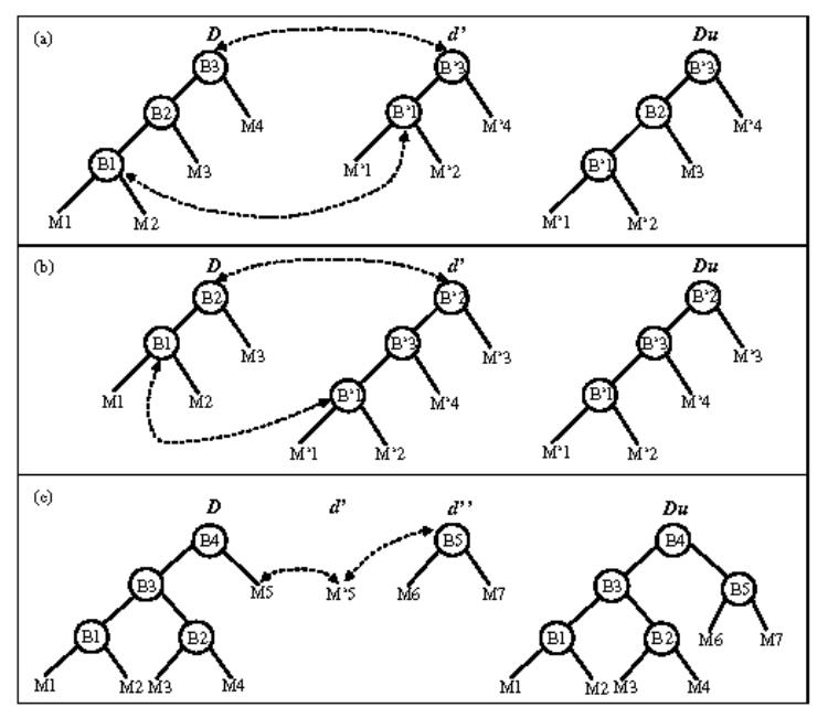
Updating of the global description for different topological events (D and Du are respectively the current and the updated global description, d′ and d″ are local descriptions): (a) in the case of the disappearance of a branch, (b) in the case of the appearance of a branch, (c) in the case of a degenerated description.
The tree insertion issue may be a more complex task when the element to be inserted is also a tree structure. Assuming that during its motion, the camera moves from a complex scene (the global description lets appear several nodes) to a simpler one like a single branch and later from this degenerated description to a branching area, the description evolves as described in Fig. 4(c). In this example M′5 corresponds to M5 in the global description, but the branch matching is impossible since d′ is degenerated. d″ does not match with D neither. Therefore, we keep a trace of the sensor displacement regarding D in order to determine an activated link, which in this case is B4 – M5. Then, thanks to the link stored previously, when d″ occurs, the local description is linked to the global one.
IV. NAVIGATION STRATEGY AND PATH PLANNING
The only environment map available to the virtual endoscope is given by the structural description it constructs by itself (scene analysis process). The virtual sensor determines its trajectory by combining information of two kinds (Fig. 5).
Fig. 5.
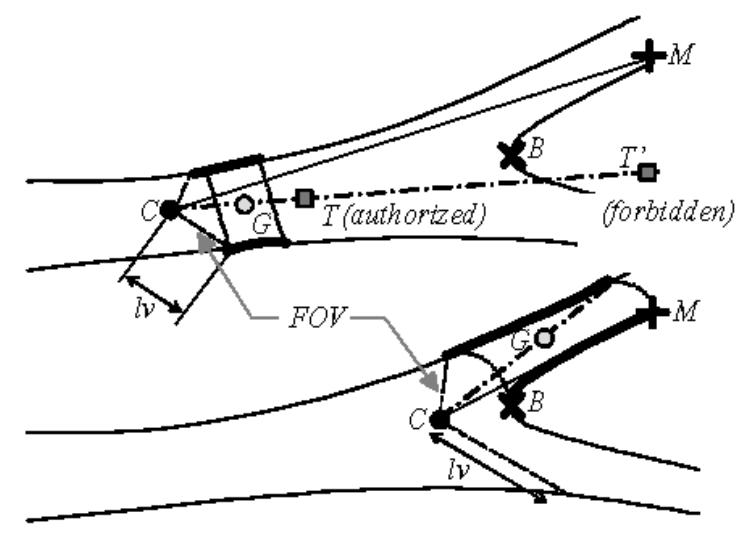
Displacement process: the bold contours represent the 3D surface points used for the computation of the displacement direction (C: optical center or virtual sensor position, CM: viewing direction, CG: displacement direction, T: local target point).
One, the viewing direction is determined according to the branch within which the sensor has to navigate. Considering that a 3D target point E has to be reached at the end of the virtual fly-through, a branch characterized by a depth maximum Ms is selected in the local description such as:
| (3) |
The depth maximum Ms is used to set up the viewing direction for the computation of the next virtual image.
Two, the direction of the next displacement within the free space is derived from the mean position G of a reduced set of 3D surface points observed by the virtual sensor. The magnitude of the displacement step MDS is chosen by the user at the beginning of the exploration. Thus, the displacement vector of the optical center C is determined by . In order to take into account the nature of the environment (bifurcation, single branch, …), the 3D surface points are selected according to their depth and the proximity or not of a border point. We define lv as the maximum depth at the periphery of the map. If the depth of the closest border is more than twice the value of lv, we assume that the virtual sensor is moving within a single branch. G is computed from the observable surface points located at a distance of less than 2lv from C. It determines a displacement vector noted Sc. If the depth of the closest border point is less than twice the value of lv, the virtual sensor is moving within a complex area (bifurcation for instance). G is computed from the observable surface points of the branch to follow located at a distance of more than the depth of the border point (region containing Ms). The displacement vector is then noted Sf.
Note that other features could have been chosen to constrain the sensor behavior. For instance, the viewing direction and the sensor displacement direction could have been fused. Our choice is mainly motivated by the fact that when a branch to follow is chosen – more particularly in a branching area –, the path planning has to be defined by the features of this particular branch, whereas the features of the other branch do not have to be considered.
In order to force the virtual sensor to stay inside the cavity, the next location, which is estimated from a current position, is compared to the depth map. To illustrate the collision detection process, we can consider a local 3D target point T and its projection in the depth map pT. The displacement of the virtual sensor is validated only if . When a collision is detected, there is no displacement and only the viewing direction is updated before the computation of the new image. If the collision is still detected, the focal length of the virtual sensor is iteratively reduced by half, in order to enlarge the field of view, and a new image is computed and analyzed at each iteration. If the virtual sensor is jammed, the navigation has to be resumed at a node from which one of the branches has not yet been explored. The restart position is given by the last location where a node with a high weighting factor was observable.
V. RESULTS
Since several parameters intervene in the proposed navigation scheme, we first study their influence both on depth map analysis for different scenes observed in patient datasets, and on virtual endoscope behavior from a phantom model dataset. We then present results of active navigation in the patient CT images.
A. Depth analysis
The size and the pattern of the convolution masks used in depth filtering constitute the a priori knowledge about the anatomical structures. In order to assess the influence of the depth selectivity parameter Nmax and of the surface detection threshold on depth maxima and consequently on border point detection, twenty different locations allowing the virtual sensor to observe various kinds of scenes (single branch, bifurcations, with or without lesion) in twenty different patient volumetric CT images have been considered. Table I summarizes the different configurations. All the tests were performed in interpolated standard helical CT images with voxel sizes ranging from 0.2×0.2×0.2 mm3 to 0.51×0.51×0.51 mm3 (slice thicknesses: from 1.5 mm to 5 mm; inter-slice distances: from 1 mm to 4 mm).
Table I.
Observed scenes in different vascular structures without (WL) or with lesions (S: stenosis, A: aneurysm, C: calcification, T: thrombus) presenting a number of observable anatomical branching points (NBP) ranging from 0 to 3. Although several of the scenes may be encountered in a same dataset, the scenes S1 to S20 were considered in different volumes.
| Scene | Vasculature | Observation | NBP |
|---|---|---|---|
| S1 | popliteal | single branch (WL) | 0 |
| S2 - S5 | popliteal | bifurcation (WL) | 4 × 1 |
| S6 | popliteal | bifurcation (SC) | 1 |
| S7 | popliteal | 2 ×1 bifurcation (WL) | 2 |
| S8 | carotid | single branch (WL) | 0 |
| S9 | carotid | bifurcation (WL) | 1 |
| S10 | carotid | 2 ×1 bifurcation (WL) | 2 |
| S11 | carotid | 3 ×1 bifurcation (WL) | 3 |
| S12 - S14 | carotid | bifurcation (SC) | 3 × 1 |
| S15 | aorta | single branch (AT) | 0 |
| S16 - S14 | aorta | bifurcation (C) | 2 ×1 |
| S18 | aorta | bifurcation (ATC) | 1 |
| S19- S20 | iliac | single branch (SC) | 0 |
At the initialization step of the active navigation process, a medical expert decided upon the position, orientation, field of view and surface detection threshold (SDTE), and an initial virtual image was computed in order to observe a particular scene. By considering contextual information (pose of the virtual angioscope in the CT volume), the expert indicated on the virtual image, where necessary, the possible location(s) of the observable anatomical branching point(s). This procedure was repeated for each of the 20 observed scenes.
Border point detection sensitivity and positive predictive value were computed by comparing the border points detected by the scene analysis process to the anatomical branching points identified by the expert. A border point was considered as a true positive when its projection in the virtual image frame was located at a distance of less than 10 pixels from the branching point indicated by the expert. The results from the border point detection comparison for different values of the depth selectivity parameter (Nmax = 3, 4, 5) and the surface detection threshold (SDT = SDTE−20%, SDTE−10%, SDTE, SDTE+10%, SDTE+20%) are summarized in Table II. For a fixed depth selectivity parameter and for each of the five surface detection thresholds there was 19 anatomical branching points in the gold standard. Computed across all twenty subjects, there was a total of 81 border points correctly detected with Nmax = 5, yielding an overall detection sensitivity of about 85 % and a positive predictive value of about 83 %.
Table II.
Border point detection sensitivity and positive predictive value (PPV) as a function of depth selectivity parameter and surface detection threshold.
| Sensitivity (%) | PPV(%) | |||||
|---|---|---|---|---|---|---|
| SDT \ Nmax | 3 | 4 | 5 | 3 | 4 | 5 |
| SDTE-20% | 83 | 83 | 89 | 79 | 79 | 81 |
| SDTE-10% | 95 | 94 | 95 | 82 | 81 | 82 |
| SDTE | 84 | 83 | 84 | 84 | 83 | 84 |
| SDTE +10% | 79 | 79 | 79 | 83 | 83 | 83 |
| SDTE +20% | 79 | 79 | 79 | 83 | 83 | 83 |
B. Virtual endoscope behavior
A phantom model representing a vessel with a stenosis and two bifurcations (Fig. 6) was used to illustrate the scene analysis process and to assess the influence of the field of view (FOV), the magnitude of the displacement step (MDS) and the choice of the starting point on the virtual path generated by active navigation. Contrast medium has been injected in the vessel lumen of a maximum of 4 mm in diameter (20 voxels) before the CT acquisition (3 mm thickness slices, reconstructed every 1.5 mm).
Fig. 6.
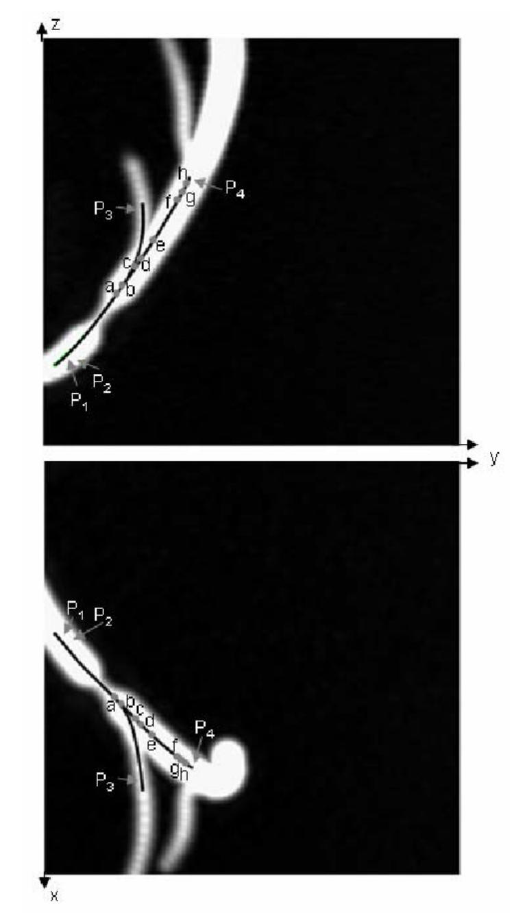
Two MIP images of the phantom model (voxel size: 0.2 × 0.2 × 0.2 mm3 after interpolation). The reference trajectories in the main branch (beginning: near points P1, P2; end: near point P4) and in the secondary branch (beginning: near points P1, P2; end: near point P3) are superimposed on the MIP images, a, b, c, d, e, f, g, and h denote eight selected poses along the virtual path in the main branch.
Fig. 7(a) shows the images as well as the local description computed by the virtual sensor inside the main branch. A starting point (P1) and a target point (P4) have been defined by the user before launching the virtual exploratory navigation. The virtual sensor passed through the lesion area and automatically reached the target point. At pose a, the vessel bifurcation is not yet detected. At poses b, c, and d, two branches characterized by two depth maxima are detected. At poses e and f, the first bifurcation has disappeared and the second bifurcation is not yet highlighted. At poses g and h, the second bifurcation is detected and represented by the local description. The global description is obtained from the matching of the successive local descriptions (Fig. 7(b)).
Fig. 7.
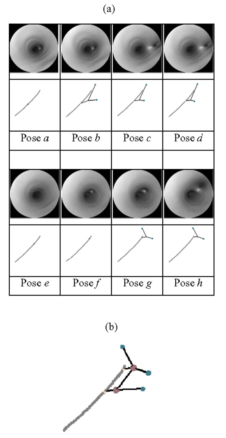
(a) Virtual images and local descriptions (gray: 3D path, child node: feature maxima, parent node: border points) constructed by the virtual sensor at 8 selected poses, (b) Global description obtained in the phantom model.
Several virtual paths have been automatically generated for different values of the navigation parameters. For a fixed target point P3 located in the secondary branch, the variable parameters were: the starting point (with two different positions P1 and P2 located in the main branch before the narrowing of the structure), the field of view FOV (120°, 140°, 160°) and the magnitude of the displacement step MDS (1, 2, 4, 8 voxels). The virtual paths have been quantitatively compared to the reference trajectory which is given by the centerline of the phantom CAD model. For each of the 24 combinations of parameters, the mean value and the standard deviation of the euclidean distances between each point of the virtual path and the closest point on the reference trajectory were used to quantify the results obtained by active navigation (Table III). The number of computed points per virtual path varied from 16 (MDS = 8) to 135 (MDS = 1). For both starting points P1 and P2, the distances between the virtual paths and the reference centerlines decrease when FOV increases. Since the surface points observable by the virtual endoscope are determined by the FOV, the best results are obtained when MDS leads to a local target position close to the center of the surface points used for the computation of the displacement direction (low FOV and high MDS, or high FOV and low MDS).
Table III.
Euclidean distance (in voxels) between the virtual path and the reference centerline. Mean (Standard Deviation) for different settings of MDS, FOV and starting point.
| MDS \ FOV | 120° | 140° | 160° |
|---|---|---|---|
| 1 voxel (P1) | 2.31 (1.59) | 1.9 (1.28) | 1.3 (1.04) |
| 2 voxels (P1) | 2.58 (1.93) | 1.79 (1.32) | 1.22 (0.94) |
| 4 voxels (P1) | 2.39 (1.88) | 1.79 (1.27) | 1.25 (0.99) |
| 8 voxels (P1) | 2.15 (1.81) | 1.7 (1.23) | 2.11 (2.02) |
| 1 voxel (P2) | 2.74 (1.92) | 2.04 (1.14) | 1.9 (1.76) |
| 2 voxels (P2) | 2.67 (1.76) | 2.03 (1.23) | 1.32 (0.93) |
| 4 voxels (P2) | 2.63 (1.85) | 2.09 (1.13) | 1.58 (1.28) |
| 8 voxels (P2) | 2.32 (1.46) | 2.89 (2.22) | 2.05 (1.14) |
As a final evaluation of virtual endoscope behavior, the evolution of the viewing direction of the virtual endoscope along the virtual path is reported in Fig. 8. for three different settings of FOV (120°, 140°, 160°) with MDS = 4 and starting point P1 One can observe that the viewing direction is nearly the same along the virtual path for FOV = 120° and 140°. The peaks between positions 60–80 correspond to the commutations between displacement vectors Sc and Sf which modify the path estimation and therefore the viewing direction. Since, with a FOV of 160°, the virtual endoscope remains closer to the centerline in the single branch area (displacement vector Sc), an important variation of the viewing direction is obtained in the bifurcation area (displacement vector Sf), whereas it becomes more stable in the single branch after the bifurcation.
Fig. 8.
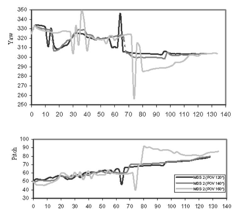
Evolution of viewing direction (pitch and yaw in degrees) along the virtual paths for different settings of FOV.
C. Virtual fly-through of patient vasculature
Our method was applied to the 20 CT volumes mentioned in Section V.1., in order to automatically navigate between a starting point and different target points defined by the user. The parameters MDS, FOV and SDT were also fixed at the beginning of the exploration. Fig. 9 shows three virtual paths obtained in the carotid arteries with stenosis as well as the detected surface points and border points. It is a typical example of the results obtained in one of the seven datasets of the carotids. Although there was an important variation of the depth maxima positions, the border points remained quite stable. Because of the complex topology in the stenosis area (calcified plaque), secondary branches have been detected. Nevertheless, the main branches were correctly matched. The bifurcation areas were successfully passed through and the virtual paths stayed inside the lumen in the different cases without any collision. Using a PC with a 2 GHz CPU and 1 GB memory, the average computation time was around 0.63s/pose (over a total number of 179 poses) for the virtual path going from P1 to E2. It varied locally from 0.6s/pose in a single branch to 1s/pose in a bifurcation area. The computation time at each main step of the algorithm was distributed in the following way: 63–73% for image computation, 4–7% for depth maxima detection, 0–13% for border points detection, and 16–26% for structural description, virtual sensor displacement and other processing tasks.
Fig. 9.
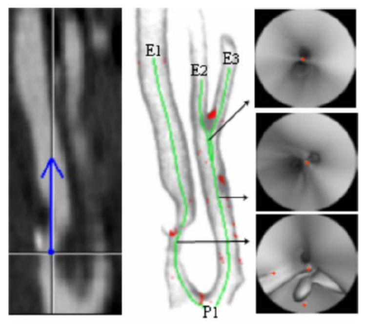
(a) CT slice at a particular position and the representation (blue) of the viewing direction of the virtual angioscope (CT acquisition parameters: 3 mm thickness slices, reconstructed every 1 mm, voxel size: 0. 24 × 0. 24 × 0.24 mm3 after interpolation). (b) Rendering showing the detected 3D surface points, the border points (red) and three virtual paths (green) computed automatically by virtual active navigation (SDT = 100 HU, FOV = 140°, MDS = 1, Nmax = 5,: starting point:P1, target points: E1, E2, E3). (c) Selected virtual angioscopy images with the representation of the border points (red).
Fig. 10 illustrates results obtained in one of the six datasets of the aorto-iliac structure. Two different virtual paths going from the supra-renal aorta to the iliac arteries have been computed. Due to the presence of thrombus and many calcified plaques, the number of secondary border points was relatively important. The target point E2 was successfully reached. Nevertheless, a secondary depth maximum at the level of a calcified plaque caused the virtual angioscope to be jammed and the target point E1 not to be reached. The backtracking from the last observable node with a high weighting factor (aorto-iliac bifurcation) did not allowed the virtual angioscope to reach the target point. Moreover, we noticed that if we start from the end of the iliac artery towards the previously mentioned starting point, by following only the deepest depth maximum, thus assuming that no bifurcation has to be observed, the virtual path is correctly completed.
Fig. 10.
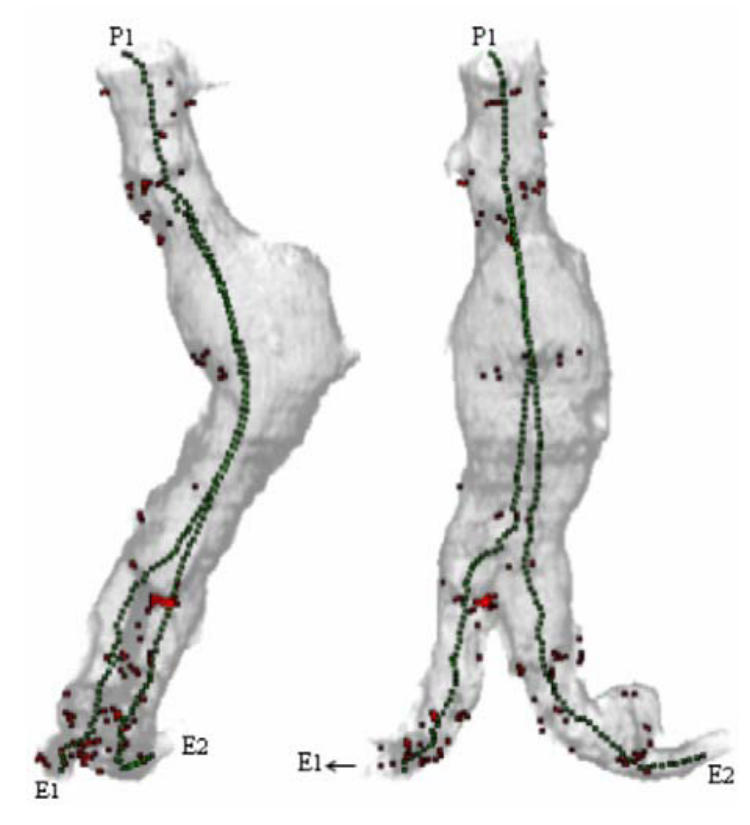
Rendering showing the detected 3D surface points, the 2D projection of the border points (red) and two virtual paths computed automatically by virtual active navigation (SDT = 90 HU, FOV = 140°, MDS = 1, Nmax = 5, starting point:P1, target points: E1, E2) in the aorta with aneurism and iliac arteries (CT acquisition parameters: 5 mm thickness slices, reconstructed every 4 mm, voxel size: 0.49 × 0.49 × 0.49 mm3 after interpolation).
In the seven datasets of popliteal arteries, the main branches were correctly passed through. Nevertheless, it was impossible to reach some lateral branches with the surface detection threshold fixed at the beginning of the navigation, i.e. at the starting point located in the main branch. Due to low contrast distribution in the bifurcation area, the relative threshold (referring to the difference between the values at the origin and along the ray) fixed in the main branch was either too low or too high to correctly detect the surface points in the small lateral branches (about 8 voxels and 1.7 mm diameter). It was confirmed by modifying the detection algorithm and considering two absolute thresholds (low threshold: detection of soft tissues, high threshold: detection of hard tissues) for which navigation from the main branch to the lateral branches were successfully completed.
VI. DISCUSSION
In the proposed virtual navigation approach, the difficulties of the tasks to be performed depend on the reliability of the detection (performance of the ray-casting algorithm in presence of low contrasted transitions, noise and artifacts), the scene complexity (shape of the surfaces bounding cavities, deviation from pipe-like cavity, hidden parts, multiple tracks, etc …), and the performance of the sensor control (obstacle avoidance, strategy to correct its pose, capability to face complex paths, and loss of control).
The quality of the scene analysis process has been assessed by considering the detection of the border points. Though the maximum probability of detecting a border point when there is an anatomical branching point (sensitivity) is 95 %, the maximum probability that a detected border point is actually an anatomical branching point is 84 %. That means that some secondary nodes do not correspond to anatomical features, notably in the lesion areas. Nonetheless they seem to be more scattered than the nodes which actually correspond to anatomical features, so that most of them might be filtered or discarded according to their weighting factor.
Several definitions of the optimality can be considered when generating virtual paths. They deal with: (i) minimal paths which are mainly concerned with robot motion planning to find the shortest path to the target [44], (ii) centerline paths which always stay inside the tubular structures and which are connected and far from the edges [20], [22], and (iii) reliable paths which ensure that the inner organ surface is fully examined [25]. Although the primary objective of this work was less to define an optimal path than to investigate a path planning approach based on active vision concept, a reference centerline has been considered in the phantom model to quantitatively appreciate the behavior of the virtual active angioscope. The closest paths to the reference centerline were generally obtained for a high field of view.
Although surface detection can be listed as a critical issue (possible failure of the detection process, volume artifacts), the study reported in this paper is not mainly aimed at dealing with this problem. The qualitative results obtained from different patient datasets (popliteal and carotid arteries) show that the interactive settlement of the surface detection threshold in the initialization step provides a simple solution to obtain successful virtual navigation inside vascular structures with lesions. The relatively high computation time compared with other tracking approaches has to be balanced by the fact that the proposed method is automatic. A minimal interaction is required from the user at the initialization step to define the surface detection threshold and to compute a virtual image at the desired starting and target points. The processing algorithms for depth map analysis and other tasks have still to be optimized, but the main time-consuming task remains image computation which may reach 73% of the total computation time. This process may be time-optimized by further considering coherency properties, such as pixel-space, voxel-space and frame-to-frame coherence, thus significantly reducing the number of cast rays and the number of detection operations per ray. Although the structural description may handle different kinds of topological events (branch appearance, disappearance), the existence of cycle (such as bypass) was not taken into account in this study. Moreover some target points were not reached due to the presence of secondary border points. The approach could be improved by reconsidering both the decision process and the surface detection process. The former was mainly concerned in this study with simple decision functions (go on with the navigation towards the target point in case of no collision, enlarge the field of view in case of a collision, select a node with a high weighting factor). It should be able to take the optimal decision to select branching candidates or to correct the virtual sensor trajectory when the target is not directly reached. Concerning the latter point, recent studies [54] allowed us to extend the geometry of the virtual sensor in order to use robust surface detection operators - consequently more time consuming - along rays cast in radial directions. An adaptive threshold could be derived from a reduced set of rays and introduced in the whole image computation process.
VII. CONCLUSION
A new method to guide the path planning in virtual angioscopy has been presented. It is based on the notion of active vision, in which visual perception completely drives the motion of the virtual sensor. The local scene interpretation during the navigation inside vascular structures allows the virtual angioscope to automatically determine its path, without the need of a pre-computed model of the patient data.
Through experiments performed on a phantom model and patient data, the conclusion that can be drawn from this study is the feasibility of the proposed method for guiding autonomous virtual sensor in complex vascular structures with lesions. Further investigations about the selection of branching candidates and the trajectory correction, could help to improve the robustness of the method. Moreover, the computation of quantitative parameters characterizing the anatomical structures from the virtual fly-through should be of main interest in clinical applications, notably for the planning of endovascular interventions. To this end, the difficulty facing us is related to the local orientation of the virtual sensor in the vessel lumen that can affect the results of the quantification. Moreover, further work should also deal with the application of virtual active navigation to other tubular anatomical structures and to spatio-temporal data.
Acknowledgments
The authors would like to thank Dr. Y. Holland, and Dr. C. Moisan for their contribution as well as Pr. J.L. Coatrieux for his helpful insights over the last years. They would also like to thank the CREATIS Laboratory (Villeurbanne, France) for providing the phantom model.
References
- 1.Oto A. Virtual endoscopy. European Journal of Radiology. 2002;42(3):231–239. doi: 10.1016/s0720-048x(02)00032-3. [DOI] [PubMed] [Google Scholar]
- 2.Fenlon HM, McAneny DB, Nunes DP, Clarke PD, Ferrucci JT. Occlusive colon carcinoma: virtual colonoscopy in the preoperative evaluation of the proximal colon. Radiology. 1999;210(2):423–428. doi: 10.1148/radiology.210.2.r99fe21423. [DOI] [PubMed] [Google Scholar]
- 3.Kay CL, Kulling D, Hawes RH, Young JW, Cotton PB. Virtual endoscopy--comparison with colonoscopy in the detection of space-occupying lesions of the colon. Endoscopy. 2000;32(3):226–232. doi: 10.1055/s-2000-100. [DOI] [PubMed] [Google Scholar]
- 4.Chen D, Liang Z, Wax MR, Li L, Li B, Kaufman AE. A novel approach to extract colon lumen from CT images for virtual colonoscopy. IEEE Trans Med Imaging. 2000;19(12):1220–1226. doi: 10.1109/42.897814. [DOI] [PubMed] [Google Scholar]
- 5.Dykes CM. Virtual colonoscopy: a new approach for colorectal cancer screening. Gastroenterol Nurs. 2001;24(1):5–11. doi: 10.1097/00001610-200101000-00002. [DOI] [PubMed] [Google Scholar]
- 6.Marsh A, Simistira F, Robb R. VR in medicine: virtual colonoscopy. Future Generation Computer Systems. 1998;14(3–4):253–264. [Google Scholar]
- 7.Hong L, Muraki S, Kaufman A, Bartz D, He T. presented at SIGGRAPH ’97. 1997. Virtual voyage: interactive navigation in the human colon; pp. 27–34. [Google Scholar]
- 8.Mori K, Hasegawa J, Suenaga Y, Toriwaki J. Automated anatomical labeling of the bronchial branch and its application to the virtual bronchoscopy system. IEEE Trans Med Imaging. 2000;19(2):103–114. doi: 10.1109/42.836370. [DOI] [PubMed] [Google Scholar]
- 9.Seemann MD, Claussen CD. Hybrid 3D visualization of the chest and virtual endoscopy of the tracheobronchial system: possibilities and limitations of clinical application. Lung Cancer. 2001;32(3):237–246. doi: 10.1016/s0169-5002(00)00228-2. [DOI] [PubMed] [Google Scholar]
- 10.Neumann K, Winterer J, Kimmig M, Burger D, Einert A, Allmann KH, Hauer M, Langer M. Real-time interactive virtual endoscopy of the tracheo-bronchial system: influence of CT imaging protocols and observer ability. European Journal of Radiology. 2000;33(1):50–54. doi: 10.1016/s0720-048x(99)00088-1. [DOI] [PubMed] [Google Scholar]
- 11.Haponik EF, Aquino SL, Vining DJ. Virtual bronchoscopy. Clin Chest Med. 1999;20(1):201–217. doi: 10.1016/s0272-5231(05)70135-0. [DOI] [PubMed] [Google Scholar]
- 12.Higgins WE, Ramaswamy K, Swift RD, McLennan G, Hoffman EA. Virtual bronchoscopy for three-dimensional pulmonary image assessment: state of the art and future needs. Radiographics. 1998;18(3):761–778. doi: 10.1148/radiographics.18.3.9599397. [DOI] [PubMed] [Google Scholar]
- 13.Summers RM, Choyke PL, Patronas NJ, Tucker E, Wise B, Busse MK, Brewer HB, Jr, Shamburek RD. MR virtual angioscopy of thoracic aortic atherosclerosis in homozygous familial hypercholesterolemia. J Comput Assist Tomogr. 2001;25(3):371–377. doi: 10.1097/00004728-200105000-00008. [DOI] [PubMed] [Google Scholar]
- 14.Unno N, Mitsuoka H, Takei Y, Igarashi T, Uchiyama T, Yamamoto N, Saito T, Nakamura S. Virtual angioscopy using three-dimensional rotational digital subtraction angiography for endovascular assessment. J Endovasc Ther. 2002;9(4):529–534. doi: 10.1177/152660280200900423. [DOI] [PubMed] [Google Scholar]
- 15.Schroeder S, Kopp AF, Ohnesorge B, Loke-Gie H, Kuettner A, Baumbach A, Herdeg C, Claussen CD, Karsch KR. Virtual coronary angioscopy using multislice computed tomography. Heart. 2002;87(3):205–209. doi: 10.1136/heart.87.3.205. [DOI] [PMC free article] [PubMed] [Google Scholar]
- 16.Sbragia P, Neri E, Panconi M, Gianni C, Cappelli C, Bargellini I, Bartolozzi C. CT virtual angioscopy in the study of thoracic aortic dissection. Radiol Med (Torino) 2001;102(4):245–249. [PubMed] [Google Scholar]
- 17.Smith PA, Heath DG, Fishman EK. Virtual angioscopy using spiral CT and real-time interactive volume- rendering techniques. J Comput Assist Tomogr. 1998;22(2):212–214. doi: 10.1097/00004728-199803000-00009. [DOI] [PubMed] [Google Scholar]
- 18.Ladd ME, Gohde SC, Steiner P, Pfammatter T, McKinnon GC, Debatin JF. Virtual MR angioscopy of the pulmonary artery tree. J Comput Assist Tomogr. 1996;20(5):782–785. doi: 10.1097/00004728-199609000-00019. [DOI] [PubMed] [Google Scholar]
- 19.Neri E, Bonanomi G, Vignali C, Cioni R, Ferrari M, Petruzzi P, Bartolozzi C. Spiral CT virtual endoscopy of abdominal arteries: clinical applications. Abdom Imaging. 2000;25(1):59–61. doi: 10.1007/s002619910012. [DOI] [PubMed] [Google Scholar]
- 20.Deschamps T, Cohen LD. Fast extraction of minimal paths in 3D images and applications to virtual endoscopy. Medical Image Analysis. 2001;5(4):281–299. doi: 10.1016/s1361-8415(01)00046-9. [DOI] [PubMed] [Google Scholar]
- 21.Swift RD, Kiraly AP, Sherbondy AJ, Austin AL, Hoffman EA, McLennan G, Higgins WE. Automatic axis generation for virtual bronchoscopic assessment of major airway obstructions. Computerized Medical Imaging and Graphics. 2002;26(2):103–118. doi: 10.1016/s0895-6111(01)00035-0. [DOI] [PubMed] [Google Scholar]
- 22.Wan M, Liang Z, Ke Q, Hong L, Bitter I, Kaufman A. Automatic centerline extraction for virtual colonoscopy. IEEE Trans Med Imaging. 2002;21(12):1450–1460. doi: 10.1109/TMI.2002.806409. [DOI] [PubMed] [Google Scholar]
- 23.Nain D, Haker S, Kikinis R, Crimson WE. In: An interactive virtual endoscopy tool,” presented at the Workshop on Interactive Medical Image Visualization and Analysis (IMIVA’01) Niessen W, Olabarriaga S, Gerritsen F, editors. Utrecht, The Netherlands: 2001. pp. 55–60. [Google Scholar]
- 24.Mori K, Hayashi Y, Toriwaki J-i, Suenaga Y, Hasegawa J-i. A method for specifying unobserved regions in virtual endoscopy system. presented at Computer Assisted Radiology and Surgery; Berlin. International Congress Series; 2001. 1230. pp. 454–461. [Google Scholar]
- 25.He T, Hong L, Chen D, Liang Z. Reliable path for virtual endoscopy: ensuring complete examination of human Organs. IEEE Transactions On Visualization And Computer Graphics. 2001;7(4):333–342. [Google Scholar]
- 26.Di Simone MP, Mattioli S, D’Ovidio F, Bassi F. Three-dimensional CT imaging and virtual endoscopy for the placement of self-expandable stents in oesophageal and tracheobronchial neoplastic stenoses. European Journal of Cardio-Thoracic Surgery. 2003;23(1):106–108. doi: 10.1016/s1010-7940(02)00620-6. [DOI] [PubMed] [Google Scholar]
- 27.Wahle A, Mitchell S, Ramaswamy S, Chandran KB, Sonka M. Virtual angioscopy in human coronary arteries with visualization of computational hemodynamics. presented at SPIE Medical Imaging: Physiology and Function from Multidimensional Images; San Diego, USA. 2001. pp. 4321–32.pp. 43 [Google Scholar]
- 28.Kuhnapfel U, Cakmak H, Maass H. Endoscopic surgery training using virtual reality and deformable tissue simulation. Computers & Graphics. 2000;24(5):671–682. [Google Scholar]
- 29.Mori K, Deguchi D, Sugiyama J, Suenaga Y, Toriwaki J, Maurer J, Takabatake CRH, Natori H. Tracking of a bronchoscope using epipolar geometry analysis and intensity-based image registration of real and virtual endoscopic images. Medical Image Analysis. 2002;6(3):321–336. doi: 10.1016/s1361-8415(02)00089-0. [DOI] [PubMed] [Google Scholar]
- 30.Bricault I, Ferretti G, Cinquin P. Registration of real and CT-derived virtual bronchoscopic images to assist transbronchial interventions. IEEE Trans Med Imaging. 1998;17(5):703–714. doi: 10.1109/42.736022. [DOI] [PubMed] [Google Scholar]
- 31.Auer DP, Sendtner P, Schneider G, Auer LM. Evaluation of virtual endoscopy for application in clinical neurosciences. presented at the 2nd Mt. BANDAI Symposium for Neuroscience; International Congress Series; 2002. pp. 141–151. [Google Scholar]
- 32.Yim PJ, Choyke PL, Summers RM. Gray-scale skeletonization of small vessels in magnetic resonance angiography. IEEE Trans Med Imaging. 2000;19(6):568–576. doi: 10.1109/42.870662. [DOI] [PubMed] [Google Scholar]
- 33.Sato Y, Nakajima S, Shiraga N, Atsumi H, Yoshida S, Roller T, Gerig G, Kikinis R. Three-dimensional multi-scale line filter for segmentation and visualization of curvilinear structures in medical images. Medical Image Analysis. 1998;2(2):143–168. doi: 10.1016/s1361-8415(98)80009-1. [DOI] [PubMed] [Google Scholar]
- 34.McInerney T, Terzopoulos D. Deformable models in medical image analysis: a survey. Medical Image Analysis. 1996;1(2):91–108. doi: 10.1016/s1361-8415(96)80007-7. [DOI] [PubMed] [Google Scholar]
- 35.Lorigo LM, Faugeras O, Grimson WEL, Keriven R, Kikinis R, Westin C-F. Co-dimension 2 geodesic active contours for MRA segmentation. Lecture Notes in Computer Science; presented at Information Processing in Medical Imaging. 16th International Conference, IPMI’99; 1999. pp. 126–139. [Google Scholar]
- 36.Wink O, Niessen WJ, Viergever MA. Fast delineation and visualization of vessels in 3-D angiographic images. IEEE Trans Med Imaging. 2000;19(4):337–346. doi: 10.1109/42.848184. [DOI] [PubMed] [Google Scholar]
- 37.Aylward SR, Bullitt E. Initialization, noise, singularities, and scale in height ridge traversal for tubular object centerline extraction. IEEE Trans Med Imaging. 2002;21(2):61–75. doi: 10.1109/42.993126. [DOI] [PubMed] [Google Scholar]
- 38.Toumoulin C, Boldak C, Dillenseger JL, Coatrieux JL, Rolland Y. Fast detection and characterization of vessels in very large 3-D data sets using geometrical moments. IEEE Trans Biomed Eng. 2001;48(5):604–6. doi: 10.1109/10.918601. [DOI] [PMC free article] [PubMed] [Google Scholar]
- 39.Bellemare ME, Haigron P, Lucas A, Coatrieux JL. Depth map based scene analysis for active navigation. presented at SPIE Medical Imaging, Physiology and Function from Multidimensional Images; San Diego, USA. 1999. pp. 202–213. [Google Scholar]
- 40.Bellemare ME, Haigron P, Coatrieux JL. Toward an Active Three Dimensional Navigation System in Medical Imaging. presented at Computer Vision, Virtual Reality and Robotics in Medicine and Medical Robotics and Computer-Assisted Surgery; Grenoble France. 1997. pp. 337–346. [Google Scholar]
- 41.Haigron P, Berre GL, Coatrieux JL. 3D navigation in medicine. IEEE Engineering in Medicine and Biology. 1996;15(2):70–78. [Google Scholar]
- 42.Luo LM, Hamitouche C, Dillenseger JL, Coatrieux JL. A moment based three dimensional edge operator. IEEE T-BME. 1993;40(7):693–703. doi: 10.1109/10.237699. [DOI] [PMC free article] [PubMed] [Google Scholar]
- 43.Souza GND, Kak AC. Vision for mobile robot navigation: a survey. IEEE Transactions On Pattern Analysis and Machine Intelligence. 2002;24(2):237–267. [Google Scholar]
- 44.Jolesz FA, Lorensen WE, Shinmoto H, Atsumi H, Nakajima S, Kavanaugh P, Saiviroonporn P, Seltzer SE, Silverman SG, Phillips M, Kikinis R. Interactive virtual endoscopy. American Journal of Radiology. 1997;169(5):1229–1235. doi: 10.2214/ajr.169.5.9353433. [DOI] [PubMed] [Google Scholar]
- 45.Lengyel J, Reichert M, Donald BR, Greenberg DP. Real-time robot motion planning using rasterizing computer graphics hardware. Computer Graphics (SIGGRAPH ’90 Proceedings) 1990;24(4):327–335. [Google Scholar]
- 46.Haddad H, Khatib M, Lacroix S, Chatila R. Reactive navigation in outdoor environments using potential fields. presented at International Conference on Robotics and Automation (ICRA’98); Leuven (Belgium). 1998. pp. 1232–1237. [Google Scholar]
- 47.Langer D, Rosenblatt J, Hebert M. A behavior-based system for off-road navigation. IEEE Transactions on Robotics and Automation. 1994;10(6):776–782. [Google Scholar]
- 48.Hait A, Simeon T, Taix M. Robust motion planning for rough terrain navigation. presented at IEEE/RSJ International Conference on Robotics and Systems; Kyongu (Korea). 1999. pp. 11–16. [Google Scholar]
- 49.Lacroix S, Chatila R. Motion and perception strategies for outdoor mobile robot navigation in unknown environments. presented at 4th International Symposium on Experimental Robotics; Stanford, California. 1995. pp. 538–547. [Google Scholar]
- 50.Hoffman H, Vu D. Virtual reality: teaching tool of the twenty-first century? Acad Med. 1997;72(12):1076–81. doi: 10.1097/00001888-199712000-00018. [DOI] [PubMed] [Google Scholar]
- 51.Lee K, Meer P, Park R. Robust adaptive segmentation of range images. IEEE Transactions on PAMI. 1998;20(2):200–205. [Google Scholar]
- 52.Besl PJ, Jain RC. Segmentation through variable-order surface fitting. IEEE Transactions on PAMI. 1988;10(2):167–192. [Google Scholar]
- 53.Rimey RD, Cohen FS. A maximum-likelihood approach to segmenting range data. IEEE Journal of Robotics and Automation. 1988;4(3):277–286. [Google Scholar]
- 54.Acosta O, Moisan C, Haigron P, Lucas A. Evaluation of Virtual Endoscopy for the Characterization of Stenosis in the Planning of Endovascular Interventions. presented at SPIE Medical Imaging: Physiology and Function from Multidimensional Images; San Diego, USA. 2002. pp. 42–53. [Google Scholar]


