1. Introduction
Tissue engineering aims to create living tissue substitutes from cells seeded onto 3-dimensional scaffolds. The role of the scaffold is to provide a temporary 3D environment that promotes cell adhesion and proliferation, provides temporary mechanical support and guides new tissue growth [1,2]. In general, the prerequisites of any scaffold design include biodegradability and a high porosity to support cell infiltration [2]. However, the design of the scaffold must also be tailored to the tissue of interest. For example, a modulus comparable to bone is an important design consideration in bone tissue engineering scaffolds [3].
Historically, scaffolds have been fabricated from biocompatible, biodegradable polymers combined with a porogen that is subsequently removed. Over the past two decades, a wide range of chemistries and pore formers have been examined to create scaffolds for tissue engineering. For example, techniques to create interconnected porous scaffolds have included fiber meshes [4], particulate leaching [5], gas foaming [6], electrospinning [7], and thermally induced phase separation [8]. Although these techniques have laid the foundation for generating porous structures for a variety of tissue engineering applications, they do not provide control over the pore structure, size or interconnectivity.
As the field of tissue engineering advances, the need for scaffolds that mimic the intricate and highly organized 3D structure of natural tissues increases. As a result, techniques such as rapid prototyping, also referred to as solid free-form fabrication, have gained increasing interest in the tissue engineering community [9,10]. Rapid prototyping utilizes a computer-aided design in combination with a specialized printer to produce a layer by layer 3D structure with intricate, reproducible features. Minimum feature sizes on the order of 100 μm have been obtained using rapid prototyping technology [3,11]. Indirect solid free form (iSSF) manufacturing has been recently developed that utilizes rapid prototyping technology in combination with traditional porogen forming techniques to create 3D porous structures. In iSSF, an inverse mold is produced by rapid prototyping, followed by infiltration of the polymer and porogen former, and then removal of the mold [12]. Using this technology, scaffolds have been fabricated to mimic the natural structure of trabecular bone, consisting of computer-designed global channels that were 500-800 μm in diameter, and local pores formed from particulate leaching that were 50-100 μm in size [12]. Rapid prototyping and indirect solid free form technologies have advanced scaffold development by enabling the creation of complex 3D architectures that mimic natural tissue structures.
Herein, we describe a simple, alternative approach to designing scaffolds with controlled microstructures, as well as macrostructures. Our approach utilizes a sphere-templating technique to control the microstructure [13], in combination with a novel photolithography process to control the scaffold macrostructure. Specifically, porous scaffolds with well-defined pore sizes were fabricated from degradable poly(2-hydroxyethyl methacrylate) (poly(HEMA)) hydrogels consisting of open, parallel channels of varying size. Scanning electron microscopy (SEM) and digital volumetric imaging (DVI) were used to visualize the 3D scaffold architectures and porous structures. To promote cell attachment, collagen type I was immobilized on the poly(HEMA) scaffolds. Electron spectroscopy for chemical analysis (ESCA) was used to determine the presence of collagen. A mouse skeletal myoblast cell line (C2C12) was seeded onto these novel scaffolds to assess their potential for tissue engineering.
2. Materials and Methods
2.1. Hydrogel Fabrication
The sphere template was prepared from uncrosslinked poly(methyl methacrylate) microspheres (PMMA, 25K MW, Polysciences, Inc. or Proflo, Beautiful Nails Products). The PMMA microspheres were placed between two glass slides in a Teflon mold (7 mm diameter, 760 μm thick) then sonicated (Aquasonic, VWR Scientific model 75 HT) for 10 minutes to compact the microspheres. The mold was heated to 140°C for 19 hours to fuse the microspheres.
To fabricate degradable poly(2-hydroxyethyl methacrylate) hydrogels, a degradable crosslinker, poly(ε-caprolactone)-b-tetraethylene glycol-b-poly(ε-caprolactone) endcapped with methacrylates, was synthesized. Briefly, 5 ml of tetraethylene glycol (TEG, Fisher Scientific, Inc.) was reacted with 35 ml of ε-caprolactone (Aldrich) in the presence of 100 μl stannous octoate (Aldrich) at 90°C for 6 hours under vacuum. The reaction was allowed to cool to room temperature. Approximately 100 ml methylene chloride and 10 ml of triethylamine were added to the reaction mixture. The reaction was cooled to 0°C and purged with nitrogen for several minutes. Methacryloyl chloride (7 ml) in 30 ml of methylene chloride was added dropwise to the reaction mixture under nitrogen. The solution was reacted overnight at 0°C and then at room temperature for an additional 24 hours. The solution was filtered to remove the triethylamine chloride salts. The final product was recovered by precipitating in cold hexane. The product was analyzed by 1H NMR. The methacrylation efficiency was calculated by comparing the area under the integral for the vinyl resonances (δ=6.1 ppm, s, δ=5.7 ppm) to the resonances for the methylene protons in TEG (δ=4.2 ppm). The methacrylation was approximately 100%. The number of ε-caprolactone units added to each side of the TEG was determined by comparing the methylene groups in the caprolactone (δ=2.3 ppm) to the methylene groups in the TEG molecule. Approximately 5 ε-caprolactone units were added to each side of the TEG molecule.
The monomer, 2-hydroxyethyl methacrylate (HEMA, Polysciences, Inc.), was purified through sequential extraction steps to remove the impurity, ethylene glycol dimethacrylate (EGDMA). EGDMA forms non-degradable crosslinks. Briefly, the monomer was diluted 1:1 with deionized water followed by four extractions with hexane to remove EGDMA. To remove the water, sodium chloride was added until saturation to force the HEMA monomer into a separate layer. Sodium sulfate was then added to the HEMA monomer to extract any residual water.
Degradable poly(2-hydroxyethyl methacrylate) hydrogels were fabricated from a monomer solution containing purified 2-hydroxyethyl methacrylate; 3 mol% degradable crosslinker (poly(ε-caprolactone)-b-tetraethylene glycol- b-poly(ε-caprolactone) endcapped with methacrylates) (mol crosslinker/mol HEMA); a photoinitiator, 1.5% (w/w) 2,2-dimethoxy-2-phenylacetophenone (Ciba Vision) in a solution of ethylene glycol (Fisher Scientific, Inc.) and distilled water (1:1.3 ratio).
Photomasks were designed in Freehand (Version 8) and printed onto transparency film using a 3600 dpi printer. The photomask was placed on top of the glass slide in the configuration described above with the sphere template. The polymerization solution was purged with nitrogen for several minutes and then poured over the microsphere template. The configuration was exposed to 365 nm initiating light using a UV light source (Novacure, Model 2100, Exfo, Inc.) equipped with a 365 nm bandpass filter and a light guide with a collimating lens adapter. The intensity was set to 4200 mW/cm2. The light guide was set 1 cm above the mold. The incident light intensity is dependent on the photomask region. The 93% opacity regions (corresponding to the desired patterned areas) resulted in an incident light intensity of ~45 mW/m2. The 0% opacity regions (corresponding to the undesired areas) resulted in an incident light intensity of ~850 mW/m2. The total exposure time was 35 s. Immediately after polymerization, the mold was dipped into an acetone/dry ice bath for 2 s to essentially stop the polymerization, and then in a methanol/ice bath for 5-15 minutes and a methanol/water (50/50) bath overnight. The polymerized gel and microsphere template were removed from the mold and placed in a 90% acetone/10% distilled water solution to dissolve the PMMA microspheres. The acetone/water solution was changed frequently for 48 hours.
2.2. Hydrogel Characterization
Hydrogels were dried under high vacuum for 2 hours. The structure of the porous and patterned hydrogels was characterized by scanning electron microscopy (FEI Sirion 30) with a 1 kV beam. The macroscopic features within the scaffold were quantified using NIH Image 1.6.
2.3. Collagen Immobilization
The hydrogels were disinfected by placing in 70% ethanol for 2 hours. The scaffolds were rinsed in sterile distilled water for 20 minutes and then dried by lyophilization. Under sterile conditions, the scaffolds were rinsed three times in acetone, then treated with 20 mM 1,1’ carbonyl diimidazole (CDI) (Aldrich Chemical Company) for 1 h at room temperature. The scaffolds were then rinsed and sonicated three times in acetone to remove unreacted CDI. Each scaffold was reacted with 0.3 mg of collagen type I (BD Biosciences) in 1 ml of carbonate/bicarbonate buffer (pH = 10.4) for 24 hours at 4°C on an orbital shaker. The gels were rinsed in phosphate buffered saline (pH 7.4) prior to use.
2.4. ESCA Analysis
Electron spectroscopy for chemical analysis was performed on a Surface Science Instruments Sprobe spectrophotometer. This instrument was equipped with a monochromatized A1 Kα X-ray source and a low energy electron flood gun for charge neutralization. The X-ray spot size was ~800 μm. A minimum of two spots were analyzed per sample. The pass energies of the emitted electrons were measured with a hemispherical energy analyzer, and ranged from 150 eV for compositional survey spectra to 50 eV for high resolution C1s scans. During spectral acquisition, the pressure in the analytical chamber was less than 5×10⁻⁹ Torr. Spectra were collected with a take-off angle of 55° resulting in a sampling depth of ~ 50 Å. The Service Physics ESCAVB Graphics Viewer program was used to determine peak areas and calculate elemental compositions from peak areas.
2.5. C2C12 Cell Studies
The scaffolds were incubated at 37°C in 100% fetal bovine serum (Invitrogen) for ~1 hour prior to seeding. A skeletal myoblast cell line (C2C12, ATCC) was used as a model cell type to examine the potential of these unique poly(HEMA) hydrogel scaffolds to support cell adhesion, spreading and growth. The scaffolds were seeded with 850,000 cells per scaffold in 15 uL in a 96-well plate, then centrifuged for 3 minutes at 150 g to facilitate cell infiltration into the scaffold. The scaffolds were transferred to a 12-well plate and cultured in Dulbecco’s Modified Eagle’s Medium (Invitrogen) supplemented with 10% fetal bovine serum at 37°C and 5% CO2 in a humid environment for four days. Media was changed daily. After four days of culture, the scaffolds were fixed in 10% neutral buffered formalin, and then processed for histological analysis or DVI.
Histological samples were dehydrated through graded ethanols/xylene and embedded in paraffin. Paraffin blocks were sectioned at 5 μm thickness onto charged Superfrost® Plus (VWR) slides, deparaffinized in xylene and rehydrated through graded ethanols and water. Sections were stained with hematoxylin (9 minutes) and eosin (3 dips), then dehydrated prior to coverslipping in Permount (Fisher Scientific). Images were obtained under differential interference contrast on a Nikon E800 upright microscope equipped with MetaMorph digital acquisition software (Universal Imaging).
DVI samples underwent whole-mount fluorescent staining to denote cell nuclei and cytoplasm, similar to a hematoxylin and eosin stain. Briefly, samples were equilibrated in 0.02M citrate buffer (pH 5.0, 1 hr), followed by overnight staining in a 0.1% eosin Y (Sigma) solution. After a 6 hr rinse in citrate buffer, samples were stained overnight in a 0.1% acridine orange (Sigma) solution, followed by an additional 2 hrs of rinsing in citrate buffer and dehydration through graded ethanols and xylene (1 hr per exchange). Samples were infiltrated in a polypropylene mold overnight with low viscosity Spurr embedding medium (Electron Microscopy Sciences) opacified with Sudan Black B (Fisher Scientific). Following infiltration, samples were cured overnight at 70°C and sectioned in a Digital Volumetric Imager (Microscience Group). The DVI (or surface imaging microscopy) sectioning process has been described previously [14]. C2C12 seeded samples were imaged with a 10X objective at a resolution of ~0.9 μm/voxel. Acridine orange/eosin fluorescence was visualized using 460-500 nm excitation light and emission filters for >600 nm (red) or 510-590 nm (green).
3. Results and Discussion
3.1. Scaffold Fabrication
Hydrogel scaffolds were created using a sphere-templating method to control pore structure, size and interconnectivity in combination with a novel photo-patterning process to independently control the macroarchitecture.
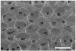
Sphere-templating techniques enable fabrication of porous materials consisting of highly interconnected spherical voids [13,15,16,17]. In this study, PMMA microspheres were utilized due to their wide range of available diameters. To control pore size, PMMA microspheres were sieved to achieve monodisperse fractions. The microspheres were close-packed via ultrasonic vibration between two glass slides and sintered at elevated temperatures to fuse the beads. The overall sintering time and temperature control the degree of fusion [18]. In this study, a sintering time of 19 hours at 140°C was used to fuse the beads – the fusion necks lead to interconnects between the pores when the beads are removed from the polymerized matrix. A representative SEM image of a cross-section of a porous hydrogel fabricated by the sphere-templating process is given in Table 1. Two monodisperse bead fractions were collected to form porous hydrogels with two different pore sizes and pores interconnects. The values are given in Table 1. The sphere-templating method allows tight control over the pore size, with standard deviations that are ~10% of the mean. An attractive feature of the sphere-templating technique is the ability to obtain uniform spherical pores, while independently controlling the pore size and interconnectivity.
Table 1.
Pore diameters and pore throat diameters
| Classification | Pore Diameters (μm)a | Pore Interconnect Diameters (μm)a |
 b b
|
|
| |||
| Small Pores | 62 ± 6 | 18 ± 2 | |
| Large Pores | 147 ± 15 | 62 ± 8 | |
based on SEM images (n=12);
representative SEM image of porous structure formed from a PMMA sphere template, where the pore interconnects can be seen by the smaller black dots (scale bar = 500 μm)
We have previously described a novel patterning process developed in our lab that is based on manipulation of polymerization kinetics to achieve patterns in thick non-degradable poly(HEMA) hydrogels [19]. In brief, patterned hydrogels were fabricated by creating an inverse photomask in which initiating light is allowed to pass through all areas of the photomask, but at different intensities. High light intensities caused significant deviations in the polymerization kinetics, resulting in longer polymerization times compared to lower light intensities. As a result, patterns in thick gels can be achieved [19]. Herein, we demonstrate that this patterning process can be used to pattern porous and degradable poly(HEMA) hydrogels. The novel photo-patterning process is illustrated in Figure 1. The infiltration of the monomer solution into the sphere template caused the PMMA sphere template to change from opaque to translucent, enabling transmittance of light through the sample. After a 35 s exposure, the partially polymerized regions corresponding to the unwanted regions under high light intensity were washed away. The PMMA microsphere template was removed through dissolution in a solution of acetone and water. The resultant gels were patterned and porous.
Figure 1.
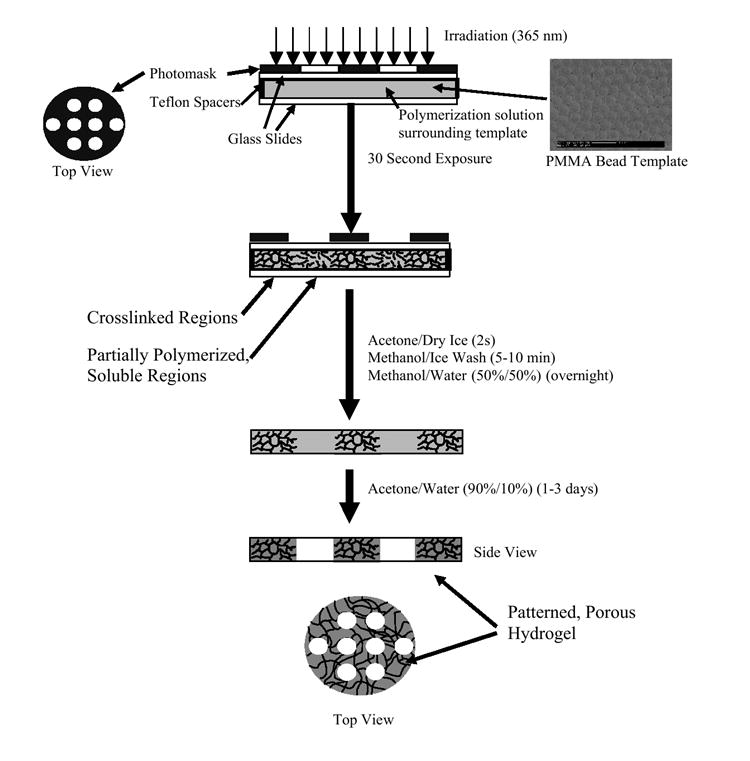
Method for patterning porous hydrogels.
The size and shape of the patterned hydrogel was controlled by the photomask. Photomasks were created with channel diameters of 200, 300, 400, and 500 μm spaced 1 mm apart. Scanning electron microscopy images of the resulting patterned gels with small and large pores are shown in Figures 2 and 3, respectively. Open channels were successfully produced in the presence of the sphere template using this novel photolithography technique, to produce patterned porous hydrogels that retained the inverse pattern of the mask with high fidelity. Using this method, a range of channel sizes was produced independent of pore size.
Figure 2.
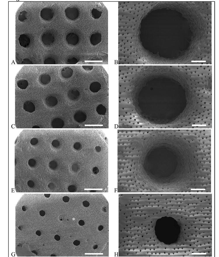
Patterned porous poly(HEMA) hydrogels with small pores (62 μm). Photomask channel diameters are 500 μm (A,B), 400 μm (C,D), 300 μm (E,F), and 200 μm (G,H). Scale bar is 1 mm for A,C,E,G and 200 μm for B,D,F,H. The * denotes bridging, which occurs when the polymerization solution is not removed prior to the onset of crosslinking.
Figure 3.
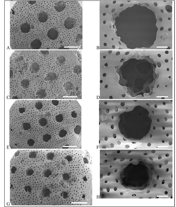
Patterned porous poly(HEMA) hydrogels with large pores (147 μm). Photomask channel diameters are 500 μm (A,B), 400 μm (C,D), 300 μm (E,F), and 200 μm (G,H). Scale bar is 1 mm for A,C,E,G and 200 μm for B,D,F,H.
The photomask channel diameters and the corresponding channel diameters that were patterned in the porous hydrogels are given in Table 2. In all cases, the channel diameter was significantly larger than the corresponding photomask dimensions. This may be attributed to several factors. First, the collimated light must transmit through 1 cm of air to the photomask made of transparency film, and then through a glass slide, before contacting the top surface of the monomer solution. These different mediums will contribute to increased beam spread and light scattering leading to decreased resolution. Second, quenching of radicals by oxygen may affect the resolution of the patterned features. The solution was purged with an inert gas prior to polymerization, yet the reaction was performed in the presence of air. Third, a dominating factor that will inherently lead to light scattering is the presence of the sphere template. Particle size and density are factors that affect the degree of light scattering. Here, the larger microsphere template resulted in larger channel diameters, compared to the smaller microsphere template under a given photomask. For example, gels prepared with the larger microsphere template resulted in channels that were 470 μm in diameter compared to the smaller microsphere template, which resulted in 360 μm channels – in both cases the photomask allowed light through 200 μm circles. These results suggest that an increase in particle size, more so than particle density, is the dominating cause for increased light scattering and hence lower resolution. Similar results were observed when poly(ethyelene glycol) hydrogels were patterned in the presence of cells [20]. Furthermore, the channel diameters tended to be larger in the center of the patterned hydrogel compared to channels along the edges (Figures 2 and 3). This result suggests that as the light hits the monomer solution, the intensity may not be uniform as a function of radial distance. The resolution of this technique may be improved by enclosing the polymerization in an inert atmosphere, or through the use of an alternative light source with a larger beam area to achieve uniform exposure across the sample.
Table 2.
Dimensions of channel diameters and channel-channel distances of photomask compared to actual dimensions based on SEM analysis
| Channel Diameter (μm) | ||
|---|---|---|
| Photomask Dimensions | Actual Dimensions | |
| Small Pores | Large Pores | |
| 500 | 700 ± 20 | 730 ± 70 |
| 400 | 600 ± 40 | 700 ± 30 |
| 300 | 370 ± 50 | 560 ± 50 |
| 200 | 360 ± 25 | 470 ± 70 |
n=6-14
In the small pore gels, bridging was evident in the 200 μm channels (Figure 2, indicated by the asterisk). Bridging occurs when the partially polymerized monomer solution is not completely removed prior to the onset of crosslinking. It is well known that these polymerizations will continue in the dark, i.e., after the light is turned off [21]. The partially polymerized, yet soluble regions will proceed to form a crosslinked gel if not dissolved and washed away immediately following the 35 s exposure. As the channel size is reduced, the potential for bridging to occur increases. From a practical perspective, bridging may be minimized by more rapidly removing the gel from the mold and quickly subjecting the gel to the methanol/water wash.
Gels with each of the pore sizes were selected to examine the cross-section of the pores and the channel. The scanning electron micrographs are shown in Figure 4. The sphere-templating technique enabled the formation of uniform spherical pores. Polymerization under the photomask did not affect the pore dimensions in the bulk of the hydrogel. The dimensions of the pores and pore interconnects in the patterned gels are similar to those listed in Table 1. In the bulk hydrogel, the spherical pores were highly uniform and interconnected as indicated by the pore throats (i.e, the smaller dark dots in Figure 4). Within the patterned channel, the pore structure differed depending on the size of the sphere template. The larger sphere template resulted in a porous structure along the channel walls that was similar to the bulk porous structure of the gel. In the presence of the smaller sphere template, however, the pore structure within the channel differed significantly from the remaining hydrogel. The pores lacked a uniform spherical shape and fewer pore interconnects were present. Immediately after polymerization, the unwanted regions must be washed away to prevent polymerization in the dark. It is possible that the smaller pores increase the time to fully wash away the partially polymerized areas, causing polymerization to continue even after the light has been turned off (i.e., in the dark). As a result, a weakly crosslinked system may form along the edges of the channel wall, in which the pores cannot maintain a spherical shape. Additional studies are necessary to understand this effect so strategies to minimize it can be developed.
Figure 4.

Cross-section of channels for the (A) porous poly(HEMA) gels with small pores (62 μm) and channel diameter of 200 μm and (B) porous poly(HEMA) gels with large pores (147 μm) and channel diameter of 300 μm.
The cross-section of the channel illustrates that the pattern was retained as a function of depth. Some tapering was observed in the channel as evident in Figure 4A. **There are several possible explanations. In thick samples (as described in this work), light absorption will vary as a function of thickness, which can affect the resolution of the pattern and result in tapered channels. Additionally, delays in the washing step that removes the partially polymerized, unwanted regions can cause continued polymerization in the dark. With the current set-up (see Materials and Methods section for details), the glass slides are often difficult to remove, particularly the side exposed directly to the UV light, which could contribute to tapered channels. Fabrication methods could be optimized to permit more efficient flushing of the unwanted regions.
A triblock copolymer crosslinker molecule consisting of hydrolytically labile ε-caprolactone units was utilized to create biodegradable patterned and porous scaffolds. Previous studies have indicated that poly(ε-caprolactone) degrades slowly (~20 months) under aqueous conditions [22]. Over the time course of our experiments (up to four days), these novel scaffolds did not undergo significant degradation, as confirmed by measurements showing no mass loss (data not shown). However, under accelerated degradation conditions (i.e., 2M sodium hydroxide) the scaffolds degraded completely overnight, indicating that these novel poly(HEMA) hydrogels are degradable. Additional chemistries, such as glycolide or lactide, may be incorporated into the crosslinker to increase degradation rate [23].
3.2. Cell Studies
Poly(HEMA) inherently exhibits low protein adsorption, and consequently, cell adhesion [24]. Therefore, cell adhesive proteins were introduced into the hydrogel to selectively control cell adhesion. In this work, collagen type I was immobilized via 1,1’ carbonyl diimidazole (CDI) onto these novel patterned and porous poly(HEMA) hydrogels to facilitate cell attachment. CDI chemistry has been used to attach proteins to polymeric surfaces including poly(vinyl alcohol) [25] and poly(HEMA) [26]. CDI was reacted with the hydroxyl side groups along the backbone of the poly(HEMA) to form an imidazole intermediate. The intermediate is highly reactive with lysine pendant amine groups that are associated with collagen type I [27].
Electron spectroscopy for chemical analysis (ESCA) was used to confirm the addition of CDI and the subsequent immobilization of collagen type I to the poly(HEMA) scaffold. It is important to note that ESCA analyzes only the surface chemistry of the poly(HEMA) scaffolds with a sampling depth of ~50 Å. Here, we analyzed the outer surface of the scaffolds. However, it may be assumed that the surfaces of the pores and the channels within the scaffold are of similar composition, since their dimensions are many orders of magnitude larger than the reacting species (CDI and collagen). Since nitrogen is not present in poly(HEMA), elemental nitrogen was assessed in the scaffolds to trace each step of the reaction. The results are given in Table 3. Poly(HEMA) scaffolds without modification showed no elemental nitrogen. When poly(HEMA) scaffolds were activated with CDI, nitrogen content increased to 0.8%. The reaction of the CDI intermediate with collagen occurs in a basic buffer solution. Poly(HEMA) scaffolds were placed in buffer without protein to serve as an internal control. The buffer solution without protein did not change the overall nitrogen content. However, the reaction of collagen type I with the CDI-activated scaffolds resulted in a significant increase in nitrogen content to 6.2%. This data indicates that collagen type I was successfully immobilized to the poly(HEMA) scaffolds.
Table 3.
Atomic percent composition of nitrogen for poly(HEMA) scaffolds
| Treatment | % Nitrogena |
|---|---|
| Poly(HEMA) | n/d |
| CDI-activated Poly(HEMA) | 0.8 ± 0.3 |
| CDI-activated Poly(HEMA) in Buffer | 0.9 ± 0.2 |
| CDI-activated Poly(HEMA) + Collagen Type I | 6.2 ± 0.7 |
n = 2-3
A mouse skeletal myoblast cell line, C2C12, was used to assess the potential of these novel materials as cell scaffolds for tissue engineering. Myoblasts were seeded onto scaffolds with the larger pore sizes and channel diameters of 730 μm. Scaffolds were cultured for four days. Post culture, the scaffolds were analyzed histologically with hematoxylin and eosin to examine cell presence and morphology. The histological micrographs are shown in Figure 5. Clumps of cells were present within the pores of the control poly(HEMA) scaffold, and although some cytoplasmic elongation was noted, little apparent adhesion to the pore surface was observed. When collagen was immobilized onto the scaffold, cells appeared to be more evenly dispersed over the scaffold, with significant evidence of cell elongation and spreading. It is important to note that the sections from the poly(HEMA) scaffolds with immobilized collagen did not adhere to the slides and were lost during histological processing. However, cellular mass remained on the slide for analysis.
Figure 5.
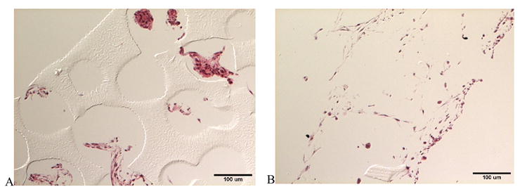
Differential interference contrast light micrographs of histological sections of C2C12 myoblasts seeded on patterned and porous poly(HEMA) scaffolds: (A) control and (B) treated with collagen type I. Imaged cross-sections were obtained from an interior area ~750 um from the edge of a scaffold disk.
The poly(HEMA) scaffolds with immobilized collagen were also examined in 3D using digital volumetric imaging technology (Figure 6). Cell nuclei fluoresce “red” due to staining with acridine orange, while cytoplasm fluoresces “green” due to eosin Y staining. The poly(HEMA) scaffolds also displayed non-specific acridine orange/eosin staining, resulting in high intensity red/green fluorescence (yellow upon overlay of signal). Significant overlap of acridine orange fluorescent signal was also seen in the cell cytoplasm, resulting in the red appearance of most cellular material. C2C12 cells were observed to adhere and spread upon the surface of the poly(HEMA). The myoblasts, which will fuse to form multinucleated myotubes upon differentiation, also appeared to form a network of fibrillar structures throughout the void space of the scaffolds. Interestingly, the cells/fibrillar structures appeared to be highly aligned circumferentially along the channel walls.
Figure 6.
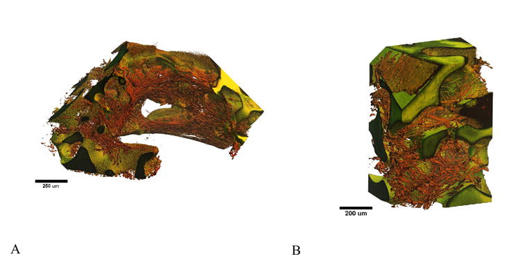
Digital volumetric imaging of C2C12 myoblasts on patterned and porous poly(HEMA) scaffolds treated with collagen. (A) Myoblasts align circumferentially along macro-channel walls. (B) Myoblasts adhered to the porous walls of the scaffold.
4. Conclusion
In summary, we describe herein a novel, simple and inexpensive approach to creating 3D scaffolds that provide independent control over the porous structure and the macroscopic patterned structure. This technique may easily be expanded to other photopolymerizable chemistries in which the polymerization kinetics under different light intensities allow for patterning. This technique provides an additional tool to tailor the 3D scaffold structure for a given cell type or tissue.
Acknowledgments
The authors are grateful for the financial support of this research through grants from the NIH (R24 HL64387) and a NIH NRSA fellowship (F32 HL74619) to SJB. Scanning electron microscopy was possible through the NSF-supported University of Washington Nanotechnology User Facility. Light microscopy and DVI were made possible through the University of Washington Engineered Biomaterials NSF-Engineering Research Center program (EEC-95,29161). The surface analysis experiments were performed at NESAC/BIO (NIBIB grant EB-002027).
Footnotes
Publisher's Disclaimer: This is a PDF file of an unedited manuscript that has been accepted for publication. As a service to our customers we are providing this early version of the manuscript. The manuscript will undergo copyediting, typesetting, and review of the resulting proof before it is published in its final citable form. Please note that during the production process errors may be discovered which could affect the content, and all legal disclaimers that apply to the journal pertain.
References
- 1.Kim BS, Mooney DJ. Development of biocompatible synthetic extracellular matrices for tissue engineering. Trends Biotechnol. 1998;5:224–230. doi: 10.1016/s0167-7799(98)01191-3. [DOI] [PubMed] [Google Scholar]
- 2.Hutmacher DW. Scaffold design and fabrication technologies for engineering tissues - state of the art and future perspectives. J Biomater Sci Polym Ed. 2001;1:107–124. doi: 10.1163/156856201744489. [DOI] [PubMed] [Google Scholar]
- 3.Hutmacher DW. Scaffolds in tissue engineering bone and cartilage. Biomaterials. 2000;24:2529–2543. doi: 10.1016/s0142-9612(00)00121-6. [DOI] [PubMed] [Google Scholar]
- 4.Freed LE, Vunjak-Novakovic G, Biron RJ, Eagles DB, Lesnoy DC, Barlow SK, Langer R. Biodegradable polymer scaffolds for tissue engineering. Bio/Technology. 1994;7:689–693. doi: 10.1038/nbt0794-689. [DOI] [PubMed] [Google Scholar]
- 5.Mikos AG, Thorsen AJ, Czerwonka LA, Bao Y, Langer R, Winslow DN, Vacanti JP. Preparation and characterization of poly(L-lactic acid) foams. Polymer. 1994;5:1068–1077. [Google Scholar]
- 6.Nam YS, Yoon JJ, Park TG. A novel fabrication method of macroporous biodegradable polymer scaffolds using gas foaming salt as a porogen additive. J Biomed Mater Res. 2000;1:1–7. doi: 10.1002/(sici)1097-4636(2000)53:1<1::aid-jbm1>3.0.co;2-r. [DOI] [PubMed] [Google Scholar]
- 7.Boland ED, Wnek GE, Simpson DG, Pawlowski KJ, Bowlin GL. Tailoring tissue engineering scaffolds using electrostatic processing techniques: A study of poly(glycolic acid) electrospinning. Journal of Macromolecular Science-Pure and Applied Chemistry. 2001;12:1231–1243. [Google Scholar]
- 8.Zhang RY, Ma PX. Poly(alpha-hydroxyl acids) hydroxyapatite porous composites for bone-tissue engineering. I. Preparation and morphology. J Biomed Mater Res. 1999;4:446–455. doi: 10.1002/(sici)1097-4636(19990315)44:4<446::aid-jbm11>3.0.co;2-f. [DOI] [PubMed] [Google Scholar]
- 9.Yeong WY, Chua CK, Leong KF, Chandrasekaran M. Rapid prototyping in tissue engineering: challenges and potential. Trends Biotechnol. 2004;12:643–652. doi: 10.1016/j.tibtech.2004.10.004. [DOI] [PubMed] [Google Scholar]
- 10.Hutmacher DW, Sittinger M, Risbud MV. Scaffold-based tissue engineering: rationale for computer-aided design and solid free-form fabrication systems. Trends Biotechnol. 2004;7:354–362. doi: 10.1016/j.tibtech.2004.05.005. [DOI] [PubMed] [Google Scholar]
- 11.Zein I, Hutmacher DW, Tan KC, Teoh SH. Fused deposition modeling of novel scaffold architectures for tissue engineering applications. Biomaterials. 2002;4:1169–1185. doi: 10.1016/s0142-9612(01)00232-0. [DOI] [PubMed] [Google Scholar]
- 12.Taboas JM, Maddox RD, Krebsbach PH, Hollister SJ. Indirect solid free form fabrication of local and global porous, biomimetic and composite 3D polymerceramic scaffolds. Biomaterials. 2003:181–194. doi: 10.1016/s0142-9612(02)00276-4. [DOI] [PubMed] [Google Scholar]
- 13.Marshall AJ, Ratner BD. Quantitative characterization of sphere-templated porous biomaterials. AICHE J. 2005;4:1221–1232. [Google Scholar]
- 14.Ewald AJ, McBride H, Reddington M, Fraser SE, Kerschmann R. Surface imaging microscopy, an automated method for visualizing whole embryo samples in three dimensions at high resolution. Developmental Dynamics. 2002;3:369–375. doi: 10.1002/dvdy.10169. [DOI] [PubMed] [Google Scholar]
- 15.Diego RB, Olmedilla MP, Aroca AS, Ribelles JLG, Pradas MM, Ferrer GG, Sanchez MS. Acrylic scaffolds with interconnected spherical pores and controlled hydrophilicity for tissue engineering. Journal Of Materials Science-Materials In Medicine. 2005;8:693–698. doi: 10.1007/s10856-005-2604-7. [DOI] [PubMed] [Google Scholar]
- 16.Ma PX, Choi JW. Biodegradable polymer scaffolds with well-defined interconnected spherical pore network. Tissue Eng. 2001;1:23–33. doi: 10.1089/107632701300003269. [DOI] [PubMed] [Google Scholar]
- 17.Marshall AJ, Ratner BD. Quantitative characterization of sphere-templated porous biomaterials. Aiche Journal. 2005;51:1221–1232. [Google Scholar]
- 18.Marshall AJ. Ph.D Thesis. University of Washington; 2004. Porous hydrogels with well-defined pore structure for biomaterials applications. [Google Scholar]
- 19.Bryant SJ, Hauch KD, Ratner BD. Spatial Patterning of Thick Poly(2-Hydroxyethyl Methacrylate) Hydrogels. Macromolecules. 2006;39:4395–4399. [Google Scholar]
- 20.Liu VA, Bhatia SN. Three-dimensional photopatterning of hydrogels containing living cells. Biomed Microdevices. 2002;4:257–266. [Google Scholar]
- 21.Berchtold KA, Haciglu B, Lovell L, Nie J, Bowman CN. Using changes in initiation and chain transfer rates to probe the kinetics of cross-linking photopolymerizations: Effects of chain length dependent termination. Macromolecules. 2001:5103–5111. doi: 10.1016/s0142-9612(02)00138-2. [DOI] [PubMed] [Google Scholar]
- 22.Tsuji H, Ikada Y. Blends of aliphatic polyesters.2. Hydrolysis of solution-cast blends from poly(L-lactide) and poly(epsilon-caprolactone) in phosphate-buffered solution. J Appl Polym Sci. 1998;3:405–415. [Google Scholar]
- 23.Sawhney AS, Pathak CP, Hubbell JA. Bioerodible hydrogels based on photopolymerized poly(ethylene glycol)-co-poly(alpha-hydroxy acid) diacrylate macromers. Macromolecules. 1993;4:581–587. [Google Scholar]
- 24.Lopez GP, Ratner BD, Rapoza RJ, Horbett TA. Plasma Deposition Of Ultrathin Films Of Poly(2-Hydroxyethyl Methacrylate)-Surface-Analysis And Protein Adsorption Measurements. Macromolecules. 1993;13:3247–3253. [Google Scholar]
- 25.Nuttelman CR, Mortisen DJ, Henry SM, Anseth KS. Attachment of fibronectin to poly(vinyl alcohol) hydrogels promotes NIH3T3 cell adhesion, proliferation, and migration. J Biomed Mater Res. 2001;2:217–223. doi: 10.1002/1097-4636(200111)57:2<217::aid-jbm1161>3.0.co;2-i. [DOI] [PubMed] [Google Scholar]
- 26.Martin SM, Ganapathy R, Kim TK, Leach-Scampavia D, Giachelli CM, Ratner BD. Characterization and analysis of osteopontin-immobilized poly(2- hydroxyethyl methacrylate) surfaces. J Biomed Mater Res. 2003:334–343. doi: 10.1002/jbm.a.10060. [DOI] [PubMed] [Google Scholar]
- 27.Hermanson GT. Bioconjugate techniques. Academic Press; San Diego: 1996. [Google Scholar]


