

Abstract
A critical step in V(D)J recombination is the synapsis of complementary (12/23) recombination signal sequences (RSSs) by the RAG1 and RAG2 proteins to generate the paired complex (PC). Using a facilitated ligation assay and substrates that vary the helical phasing of the RSSs, we provide evidence that one particular geometric configuration of the RSSs is favored in the PC. To investigate this configuration further, we used fluorescent resonance energy transfer (FRET) to detect the synapsis of fluorescently labeled RSS oligonucleotides. FRET requires an appropriate 12/23 RSS pair, a divalent metal ion, and high-mobility-group protein HMGB1 or HMGB2. Energy transfer between the RSSs was detected with all 12/23 RSS end positions of the fluorescent probes but was not detected when probes were placed on the two ends of the same RSS. Energy transfer was confirmed to originate from the PC by using an in-gel FRET assay. The results argue against a unique planar configuration of the RSSs in the PC and are most easily accommodated by models in which synapsed 12- and 23-RSSs are bent and cross one another, with implications for the organization of the RAG proteins and the DNA substrates at the time of cleavage.
The assembly of the gene segments coding for the variable portions of lymphocyte antigen receptors (immunoglobulins and T-cell receptors) occurs via a somatic recombination reaction known as V(D)J recombination. This process is mediated by two lymphoid cell-specific factors, RAG1 and RAG2 (recombination-activating gene products), that perform DNA cleavage at a pair of recombination signal sequences (RSSs) flanking the coding segments to be joined. RSSs consist of short palindromic heptamer and A/T-rich nonamer elements separated by a less well conserved spacer of 12 or 23 bp (12-RSS and 23-RSS). In vivo, recombination occurs most efficiently with a 12/23 RSS pair, a phenomenon referred to as the 12/23 rule.
Under appropriate conditions in vitro, the RAG proteins together with high-mobility-group protein HMGB1 or HMGB2 perform coupled DNA cleavage of RSS substrates in accordance with the 12/23 rule (16). This process is thought to be initiated by the binding of the RAG recombinase to one RSS, followed by the capture of a second RSS, thus assembling the synaptic, or paired, complex (PC) (22, 28). HMGB1 and HMGB2 proteins play critical roles in vitro in facilitating the binding of the RAG proteins to the 23-RSS and the formation of the PC (15, 16), activities thought to rely on their ability to recognize bent or distorted DNA structures (3, 7). DNA cleavage takes place in two steps: a nick is first introduced between the heptamer and the coding DNA, and the 3′ hydroxyl group thus liberated then attacks the other strand of the duplex to generate a covalently sealed hairpin coding end and a blunt signal end (16). Nicking can occur before or after synapsis, but hairpin formation occurs coordinately at the two RSSs within the PC (15). The PC is thus a critical intermediate in which the recombining partners are chosen and DNA double-strand breaks are made.
Numerous studies have identified functionally important residues and domains within the catalytically essential, or core, region of RAG1 (10): an N-terminal nonamer binding domain that interacts with the RSS nonamer, a central domain that interacts with RAG2 and the heptamer and contains two of three acidic residues thought to contribute to the RAG active site, and a C-terminal domain with dimerization and nonspecific DNA binding activity and the third active-site residue. Less is known about the RAG2 core region.
The structure of the PC is poorly understood. The PC is thought to contain two (37) or more than two (28) RAG1 monomers, two monomers of RAG2 (28, 37), and an unknown number of HMGB1 or HMGB2 subunits. The nonamer binding and catalytic domains that interact with a particular RSS are contributed by different RAG1 monomers (36). This and the dependence of hairpin formation upon synapsis suggest careful coordination between the catalytic events at the two RSSs, a possibility supported by the finding that nicking at one RSS is required for hairpin formation at the partner RSS (41).
Very little is known about the structure of the two DNA molecules in the PC. RAG1/2 and HMGB1/2 together induce bends in the 12- and 23-RSSs (1), and it is reasonable to think that the RSSs are also bent in the PC, although this has not yet been demonstrated. Recombination in vivo (33) and coupled DNA cleavage in vitro (12) are more sensitive to a short intersignal distance when the RSSs are oriented to mediate inversional recombination (which occurs with RSSs in direct repeat orientation) than when they are oriented to mediate deletional recombination (which occurs with RSSs in inverted repeat orientation), findings which support the parallel (as opposed to antiparallel) alignment of the two RSSs (33). No direct assessment of RSS orientation in the PC has thus far been carried out.
DNA footprinting and cross-linking studies have provided information about protein-DNA contacts in both pre- and postsynaptic RAG-RSS complexes (35). Contacts are detected throughout the RSS, are biased toward one face of the DNA helix, and are similar for the 12- and 23-RSSs. RAG1 interactions with the nonamer are evident, and contacts with the heptamer become stronger in the presence of RAG2, which itself seems to most closely contact the DNA near the site of cleavage.
The RAG1/2 complex has transposition activity and striking mechanistic similarities to transposases, particularly, a subclass of cut-and-paste transposases that perform DNA cleavage via a hairpin intermediate (30). For one of these, the Tn5 transposase, the structure of a (postcleavage) synaptic complex has been determined previously, revealing that the two DNA molecules are approximately coplanar and antiparallel and that both Tn5 monomers have extensive contacts with both DNA molecules (9). An important constraint faced by the RAG proteins is the need to bring the key DNA elements (heptamer and nonamer) of two substrates of different lengths (12-RSS and 23-RSS) into a productive configuration for cleavage while excluding two substrates of similar lengths (12/12 or 23/23).
We have used facilitated ligation and fluorescence resonance energy transfer (FRET) assays to begin to understand how RAG1 and RAG2 have solved this problem. The ligation results suggest that one particular geometric configuration of the RSSs in the PC is preferred. We then designed a series of fluorescently end-labeled oligonucleotide 12/23 RSS substrates with the expectation that certain configurations of the fluorophores would support energy transfer upon synapsis while others would not. Surprisingly, all different 12/23 RSS configurations tested yielded significant FRET, although little or no energy transfer was seen with 12/12 or 23/23 RSS combinations or with those in which the donor and acceptor were placed in cis at the two ends of the same RSS. While we cannot rule out the existence of multiple, structurally distinct synaptic complexes, we favor the simpler possibility that a single, unique RSS organization exists in the PC. Our findings place significant constraints on the organization of the RSSs in the PC, in particular by arguing against the types of planar parallel or antiparallel configurations considered previously. Instead, the simplest interpretation is a crossed configuration of the RSSs in which both DNA molecules are bent.
MATERIALS AND METHODS
Oligonucleotide RSS substrates.
Unlabeled and fluorescently labeled deoxyoligonucleotides were synthesized and purified by high-pressure liquid chromatography by Integrated DNA Technologies Inc. (Coralville, IA). The DNA substrates labeled at the 5′ end with fluorophores were made by annealing the following oligonucleotides with their complements: 12-RSS, 5′-GATCTGGCCTGTCTTACACAGTGATACAGACCTTAACAAAAACCTGCACTCGAGCGGAG-3′, and 23-RSS, 5′-GATCTGGCCTGTCTTACACAGTGATGGAAGCTCAATCTGAACTCTGACAAAAACCTCGAGCGGAG-3′. The fluorophores used, 6-carboxyfluorescein (FAM) and the carboxytetramethylrhodamine (TAMRA)-N-hydroxysuccinimide ester, were attached during synthesis by using nucleotides (an amino-modified nucleotide in the case of TAMRA) labeled at the 5′ end with phosphoramidite. In some experiments, a shorter 12-RSS oligonucleotide labeled at the 3′ end with FAM, 5′-GTCGACCACAGTGCTACAGACTGGAACAAAAACCCTGCAG-3′, was used. A shorter length was chosen for the 3′-end-labeled substrates (40 versus 59 nucleotides for the 5′-end-labeled 12-RSS) to ensure that the substrates would be of a homogeneous length. The annealing of oligonucleotides to generate double-stranded DNA was performed in binding buffer (BB; 10 mM Tris-HCl [pH 7.5], 50 mM NaCl, 5 mM MgCl2) by heating the complementary oligonucleotides mixed in equimolar amounts for 5 min at 95°C, followed by slow cooling to room temperature. To generate the prenicked substrate, the oligonucleotide 5′-GATCTGGCCTGTCTTA labeled with FAM at its 5′ end and 3′ dideoxy modified was mixed with the 5′-end-phosphorylated oligonucleotide 5′-CACAGTGCTACAGACTGGAACAAAAACCCTGCAG-3′ and annealed to the full-length 12-RSS bottom strand. The annealed, double-stranded, prenicked substrate was gel purified to remove any single-stranded unincorporated DNA.
Plasmids and DNA constructs.
Constructs S77 to S104 used in the facilitated ligation assay varied in length by 3-bp steps, contained XbaI sites at their ends, and were synthesized starting from IS95 (5) by using a two-step PCR approach (27) (primer sequences are shown in Table 1). In the first step, two amplification reactions were performed using IS95 DNA as the template and primers 1M and 2M or primers 3M and 4M. The two amplification products obtained in step one were mixed and used as the template for the second-step amplification along with primers 1M and 4M (with XbaI sites). The 3M primers were unique for each construct and were designed to have a 25-nucleotide sequence complementary to the 5′ end of primer 2M such that the overlap of the 2M and 3M primers would create the appropriate insertion or deletion of residues in the interval between the two RSSs. The products of the second-step PCR were cloned into the XbaI site of a modified pUC19 plasmid lacking a HindIII site (details and construct sequences are available upon request).
TABLE 1.
Sequences of oligonucleotides used in the construction of the helically phased DNA substrates
| Primer | Sequence (5′ to 3′)a |
|---|---|
| 1M | AGCTGCTCTAGAACAGCTATGACCATGATT |
| 2M | CGCAGTATCAGCCATGGATCTGCAGGGTTTTTGTTCCAGTCT |
| 3M-IS77 | GATCCATGGCTGATACTGCGGCCAATCGAGCCATGTCGTCGTCGA |
| 3M-IS80 | GATCCATGGCTGATACTGCGCGCGCCAATCGAGCCATGTCGTCGT |
| 3M-IS83 | GATCCATGGCTGATACTGCGTGTCGCGCCAATCGAGCCATGTCGT |
| 3M-IS86 | GATCCATGGCTGATACTGCGACTTGTCGCGCCAATCGAGCCATGT |
| 3M-IS89 | GATCCATGGCTGATACTGCGGTAACTTGTCGCGCCAATCGAGCCA |
| 3M-IS92 | GATCCATGGCTGATACTGCGGCAGTAACTTGTCGCGCCAATCGAG |
| 3M-IS98 | AGTCTGATCTAAGCTTGCCTGCAGTGTTAACTTGTCGCGCCAATCG |
| 3M-IS101 | AGTCTGATCTAAGCTTGCCTGCAGTCCATGGAACTTGTCGCGCCAA |
| 3M-IS104 | AGTCTGATCTAAGCTTGCCTGCAGTCCATGGGTTAACTTGTCGCGCCAA |
| 4M | TAGTGCTCTAGATTAGCTTCCTTAGCTCCT |
Underlining indicates XbaI sites.
Protein purification.
Throughout this work, RAG1 denotes core RAG1 (amino acids [aa] 384 to 1008), which was fused at its N terminus to maltose binding protein (MBP) and tagged at its C terminus with six histidine residues. RAG2 denotes core RAG2 (aa 1 to 383), which was fused at its N terminus to glutathione S-transferase (GST). These proteins were expressed and purified as previously described (15). Murine HMGB2 (aa 1 to 185) lacking the C-terminal acidic domain was expressed and purified as described previously (13). Full-length, polyhistidine-tagged HMGB1 purified from insect cells was a kind gift from P. Tattersall.
Facilitated ligation assays.
All ligation and cleavage reactions were performed in main buffer (10 mM Tris-HCl [pH 7.4], 50 mM KCl, 2.5 mM MgCl2, 1 mM ATP). The labeled substrate DNA (final concentration, 3 nM) was incubated for 10 min at 25°C either in the absence of any protein or with 22.5 nM HMGB2 mixed with 6 nM MBP-RAG1 carrying the D708A RAG1 mutation and without (HMGB2 control reactions) or with (complete reaction) 12.5 nM GST-RAG2. T4 DNA ligase (200 U; New England Biolabs) was then added with rapid mixing, and the reaction mixture was incubated an additional 2 min at the same temperature (5). Reactions were stopped by the addition of EDTA (16 mM final concentration), and DNA was purified by proteinase K treatment, phenol-chloroform extraction, and ethanol precipitation. The purified DNA was resolved on 5% acrylamide-Tris-borate-EDTA native gels which were dried and exposed for 24 h and imaged with a PhosphorImager (Molecular Dynamics). The scanned images were quantified using ImageQuant 5.2 (Molecular Dynamics).
DNA cleavage and binding assays.
The DNA probes used for DNA cleavage and binding assays were generated by 5′-end labeling of the top strand of the 12- or 23-RSS with T4 polynucleotide kinase (New England Biolabs) and [γ-32P]ATP (3,000 Ci/mmol; New England Nuclear), purification on a 7.5% acrylamide-8 M urea denaturing polyacrylamide gel (PAG), annealing to the complementary strand (fluorescently labeled in some cases) as described above, and gel purification on a 5% nondenaturing PAG. Cleavage assays (final assay mixture volume, 15 μl) were performed in BB by incubating 5 nM doubly (fluorescently and radioactively) labeled RSS DNA substrates in the absence or presence of the complementary RSSs (either in equimolar amounts or in a fivefold molar excess with respect to the radioactively labeled probe), 500 nM HMGB2, 65 nM RAG1, and 125 nM RAG2 at 37°C for the length of time indicated in Fig. 3B. Cleavage was stopped by the addition of EDTA to 16 mM followed by deproteinization and ethanol precipitation. The purified DNA strands were separated on 8.5% acrylamide-Tris-borate (TB)-8 M urea-40% formamide denaturing gels, which were dried and visualized using a PhosphorImager. Electrophoretic mobility shift assays (EMSAs; final assay mixture volume, 15 μl) were performed in Ca2+-modified BB (in which 5 mM MgCl2 was replaced by 5 mM CaCl2) by incubating 5 nM doubly labeled RSS DNA substrates in the absence or presence of their complementary RSSs or nonspecific DNA, 500 nM HMGB2, 65 nM RAG1, and 125 nM RAG2 at 25°C for 20 min. Samples were resolved on 6% acrylamide 37.5:1 (acryl-bisacryl) native PAGs in 0.5× TB buffer (45 mM Tris [pH 8.9], 45 mM borate) at room temperature. Gels were dried and visualized using a PhosphorImager.
FIG. 3.

Fluorophore-labeled 12- and 23-RSS substrates support RAG-mediated synapsis and cleavage in conventional assays. (A) EMSA using as a probe 5 nM 23-RSS doubly 5′ end labeled with FAM (circle) at its nonamer end and with 32P (star) at its heptamer end. Partner RSSs were omitted (lane 2) or added at 1× or 5× stoichiometry as indicated above the lanes (TAMRA is indicated as a black oval). Lane 1, no protein; lanes 2 through 9, 65 nM RAG1, 125 nM RAG2, and 500 nM HMGB2. Only the portion of the gel containing the shifted complexes is shown. Two exposures are provided to allow clear visualization of both strong and weak bands. 12- and 23-RSSs are indicated by white and gray triangles, respectively. The SC and PC are indicated by arrows. + and −, presence or absence, respectively, of the indicated component. (B) Kinetics of RAG-mediated DNA cleavage using the same doubly labeled 23-RSS (5 nM) as that described in the legend to panel A. The RAG and HMGB (HMG) proteins and 12-RSS partner were added as indicated above the lanes, and cleavage was allowed to proceed for the times (min) indicated. The structure and stoichiometry of the three partner RSSs are indicated at the top, using symbols as described in the legend to panel A. Lanes 1, 6, and 10, no protein; all other lanes, 65 nM RAG1, 125 nM RAG2, and 500 nM HMGB2. Lane 2, no partner RSS. The input substrate and nicked and hairpin products can be visualized, as depicted schematically at the right.
In-gel FRET.
EMSAs were performed as described above by using as probes RSS oligonucleotides doubly labeled with FAM and 32P in the absence or presence of a complementary partner RSS either unlabeled or labeled with TAMRA. Binding reactions were performed as described above, and products were resolved on discontinuous native PAGs (upper two-thirds, 4% acrylamide; bottom third, 7.5% acrylamide, 37.5:1 [acryl-bisacryl]) in 0.5× TB buffer. After electrophoresis, the wet gels were scanned using a FluorImager 595 (Molecular Dynamics) with a laser excitation filter of 480 nm and an emission filter of 530 nm. The gels were then exposed twice to PhosporImager screens, first while wet (20-min short exposure) and second when dry (16 h). Fluorescent and radioactive intensities of bands corresponding to each protein-DNA complex were quantified using ImageQuant 5.2, and results were expressed as percentages of the quenching of FAM fluorescence (for the equation used in the calculation, see Fig. 6A).
FIG. 6.

Detection of energy transfer in the PC by using an in-gel FRET assay. (A) Schematic diagram of the in-gel FRET assay. A 23-RSS labeled with the donor (circle) and 32P (star) was incubated with the RAG and HMGB2 proteins and either an unlabeled 12-RSS (lane 1) or a 12-RSS labeled with the acceptor (oval; lane 2). After gel electrophoresis, donor fluorescence (F) and radioactivity (R) were determined for each band and the percentage of quenching was determined as indicated by the formula. See the text for additional details. (B) EMSA using a discontinuous 4%/7.5% polyacrylamide gel. RSSs are indicated above the lanes by the symbols used in panel A; 12T indicates the 12-RSS labeled with TAMRA at its 5′ nonamer end. RAG proteins and partner RSSs were added as indicated above the lanes. U, unlabeled partner; L, TAMRA-labeled partner, +, present; −, absent. The same gel was scanned for radioactivity (left image) or fluorescence (right image) as described in Materials and Methods. Quantitation of lanes 5 and 6 allowed the percentages of quenching to be calculated for the PC (9.23%) and the SC (0.50%). Lane 1 shows that only the SC is formed in the absence of a partner. Lane 3 shows that a doubly labeled 12-RSS generates shifted complexes of the same mobility as the doubly labeled 23-RSS. (C) Results obtained from in-gel FRET experiments with the three configurations of fluorophores depicted, expressed as percentages of quenching of FAM fluorescence ± standard deviations (SD). The number of independent measurements made is indicated in parentheses below each value. Note that in some experiments, only one of the two shifted complexes was visualized and quantitated.
In-solution fluorescence data acquisition and analysis.
Emission fluorescence spectra were recorded on a Photon Technology International C-61 T-format fluorometer equipped with a circulating water bath to control cell temperature. All fluorescence measurements were performed with 150-μl quartz cuvettes (Starna, Atascadero, CA) at a 25°C constant temperature maintained by a circulating water bath. The emission fluorescence spectra were recorded with an excitation wavelength of 492 nm by using an 8-nm band pass for both the monochromator and the emission long pass. All fluorescence emission spectra were recorded between 510 and 650 nm by using 1-nm steps and 2-s integration times. Protein-DNA mixing for various samples was done in ice-cold BB buffer and was followed by a 10-min incubation at 25°C. After incubation, each sample mix was moved into the quartz cuvette for recording. For those samples containing a complete protein mix (RAG1, RAG2, and HMGB2), the first spectral recording was followed by a 10-min incubation at 25°C and a second recording. No photobleaching was detected between any two successive recordings. The standard complete reaction mixture contained 5 nM FAM-labeled RSS DNA (donor), 25 nM TAMRA-labeled RSS (acceptor), 1 μM HMGB2, 125 nM RAG1, and 250 nM RAG2. Control reaction mixtures, in which synapsis should not occur, were identical but lacked RAG2. Spectra were corrected for background created by lamp fluctuations and the lamp's wavelength dependence. The emission intensities of all spectra were expressed as relative numbers as detected by the photomultiplier. A standard rhodamine reference (constant emission output of ≈46,500 counts at its maximum wavelength of 580 nm) excited with the same source was used to monitor for emission intensity fluctuations. If sample absorption at the excitation wavelength exceeded 0.001 optical density unit, inner filter corrections were also applied according to the data in reference 23.
For each FRET experiment for a particular configuration of donor and acceptor fluorophore probes, emission spectra (excitation λ, 492 nm) were recorded for the following samples: (i) donor and acceptor RSSs or (ii) only the acceptor RSS, incubated with HMGB2 and RAG1 in the absence of RAG2, and (iii) donor and acceptor RSSs or (iv) only the donor RSS or (v) only the acceptor RSS, incubated with the complete protein mixture for 10 or 20 min. In addition, spectra were recorded for the donor RSS alone (no protein) and for the acceptor RSS alone (no protein) at 10 and 20 min, yielding data used by the Felix software (Photon Technology International) to calculate correction coefficients. The emission spectra shown in the figures (see Fig. 4 and 5) were obtained by subtracting the value for item ii above from that for item i to yield the no-RAG2 trace or the value for item v from that for item iii to yield the total-RAG-mix traces. The use of subtracted spectra corrects for the residual emission arising from the direct excitation of the acceptor.
FIG. 4.

Detection of the PC by FRET. Donor and acceptor RSS substrates were incubated with RAG1 and HMGB2 but no RAG2 or with RAG1, RAG2, and HMGB2 (total RAG mix) for 10 or 20 min in an Mg2+ buffer as described in Materials and Methods. Steady-state emission spectra were recorded using an excitation wavelength of 492 nm, and the spectra determined by subtraction (to correct for background TAMRA emission) are shown (see Materials and Methods). (A) Steady-state emission spectra obtained using a 23-RSS labeled at its heptamer end with FAM and a 12-RSS substrate (fivefold molar excess) labeled at its nonamer end with TAMRA. Fluorescence I, fluorescence intensity expressed in arbitrary units. (B) Steady-state emission spectra obtained using a 23-RSS labeled at its heptamer end with FAM and a 12-RSS (fivefold molar excess) labeled at its heptamer end with TAMRA. Results for the no-RAG2 control and the total RAG mix (10-min time point) are shown, as is the spectrum obtained for the total RAG mix after the addition of EDTA to a final concentration of 17 mM (20-min time point). +, with; −, without. (C) FRET requires HMGB2. Using the same configuration of fluorophores described in the legend to panel B, spectra were recorded (in the absence of HMGB2) with RAG1 alone and with RAG1 and RAG2 at 10 and 20 min.
FIG. 5.

FRET is 12/23 restricted and does not occur with fluors located in cis. Steady-state emission spectra were recorded as described in the legend to Fig. 4 by using the combinations of substrates depicted. (A) 12-RSS with FAM at the heptamer end and 12-RSS with TAMRA at the nonamer end. (B) 23-RSS with FAM at the heptamer end and 23-RSS with TAMRA at the nonamer end. (C) Doubly labeled 12-RSS with FAM at the heptamer end and TAMRA at the nonamer end with an unlabeled 23-RSS. (D) Doubly labeled 23-RSS with FAM at the heptamer end and TAMRA at the nonamer end with an unlabeled 12-RSS. Symbols are as defined in Fig. 4. Fluorescence I, fluorescence intensity expressed in arbitrary units.
Quenching of the FAM donor was not found consistently in our spectra, particularly in experiments involving 12-RSS substrates labeled with FAM at the 5′ end flanking the heptamer. For these RSSs, RAG binding led to an increase or a smaller-than-expected decrease (based on acceptor emission) in donor fluorescence. We attribute these effects to protein-fluorophore interactions that decrease the excited-state lifetime or the quantum yield of the FAM fluorescent probe since for these samples an increase in FAM fluorescence was observed even in the absence of a TAMRA-labeled partner.
Quantitation of the energy transfer efficiency was therefore calculated from the emission spectra by the acceptor sensitization method of Fairclough and Cantor (14):
 |
(1) |
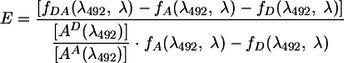
where E is the FRET efficiency and f(λ492, λ) represents the numerical integral of the emission spectrum excited at 492 nm between λ of 565 and 620 nm. The subscripts denote spectra as follows: A, no-RAG2 spectra; DA, total-RAG-mix spectra; and D, donor RSS with total RAG protein mix. AD(λ492) and AA(λ492) denote the absorbance values of the donor and acceptor fluors, respectively, at the maximum excitation λ of FAM of 492 nm.
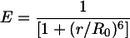
The distances between the ends of the 12-RSS and the 23-RSS substrates were calculated based on the average FRET efficiency E for fluorophores positioned at those ends. Because two sets of experiments (differing only by the exchange of the fluorophore positions) investigated the distance between any two ends, the value of E used was the average of the two mean values obtained for these two configurations. End-to-end distances were calculated as the interfluorophore distance, r, which is related to E and the Förster radius (R0, the distance at which the energy transfer is 50% efficient) for the FAM-TAMRA pair of fluorescent dyes (R0, 55 Å, which assumes a rotational-diffusion randomized value of the dipole orientation factor κ2 of 2/3) by the following equation (6, 32):
 |
(2) |
The equations were solved numerically using Maple 7.0 software.
RESULTS
Facilitated ligation of helically phased substrates.
Previous studies suggested that DNA cleavage by the RAG proteins occurs with one particular orientation of the RSSs in the PC (12, 33), and it is plausible that a stable PC also forms preferentially with one configuration of the RSSs. Alternatively, stable synapsis may occur with two or more configurations of the RSSs with only one supporting cleavage and the others being nonproductive. Assays that use cleavage as an end point cannot address this issue.
To test directly whether synapsis requires a particular geometric configuration of the RSSs, we designed a facilitated ligation experiment in which the rigidity of the DNA double helix was used to constrain the relative orientations of the two RSSs. The prototype DNA substrate, S89, was 256 bp long with compatible cohesive ends and contained a 12-RSS and a 23-RSS separated by 89 bp (8.5 turns of the DNA helix) (Fig. 1A). In the other substrates, the separation between the RSSs varied systematically in steps of 3 bp, from 77 to 104 bp, with each 3-bp increment changing RSS phasing by ≈ 103°. This is indicated by the rotation of the arrow assigned to the 23-RSS (Fig. 1C; the 12-RSS arrow does not move and is arbitrarily set pointing up).
FIG. 1.

Synapsis occurs preferentially for a unique helical orientation of the RSSs. (A) The prototype substrate for the facilitated ligation assay, S89, contains 89 bp between the nonamers of the 12-RSS and 23-RSS (white and gray triangles and arrows, respectively) and 50-bp left and right flanks terminating in XbaI-compatible ends. Black arrows indicate the relative orientations of the two RSSs. (B) The RSS is depicted as a triangle with the wide side corresponding to the heptamer (hep) and the narrow side corresponding to the nonamer (non). A vertical arrow indicates the site of cleavage. (C) The other substrates differ from S89 by increments of 3 bp in the distance separating the two RSSs. The relative orientations of the two RSSs are represented by arrows on clock faces with the arrow for the 12-RSS arbitrarily set pointing up. (D) Ligation (circularization) efficiencies for each of the 10 substrates. Values for each substrate are the averages of results from three independent experiments and were normalized to the ligation efficiency seen with RAG1 (R1) and HMGB2 for that substrate (error bars indicate standard deviations).
An important feature of the substrates was that the intersignal distance was less than the persistence length of duplex DNA (150 bp), and as a consequence, the DNA was very resistant to bending and torsional twisting (34, 40). After binding to the first RSS (along one face of the helix [35, 38]), the RAG proteins would attempt to bind to the appropriate face of the second RSS—and depending on the RSS phasing, this binding might require a significant torsional twist of the DNA. For DNA of the size of these substrates, a torsional twist of one half turn of the helix requires 2.8 to 3.5 kcal/mol, while the free energy of binding for high-affinity DNA binding proteins such as the LacI repressor is −8.5 kcal/mol (17, 21). Hence, if the two RSSs are out of phase, a significant fraction of binding energy must be expended to bring the RSSs into proper alignment. If only one geometric configuration is allowed in the PC, then ligation efficiency should exhibit a phasing of 10.5 bp, which would reveal itself by maximal ligation efficiency for two substrates whose intersignal distance differs by 21 bp, or two full helical turns. If, however, multiple geometric configurations are compatible with synapsis, such phasing should not be observed.
Ligations with T4 DNA ligase only or with preincubation with RAG1 and HMGB2 (no synapsis) or with RAG1, RAG2, and HMGB2 (synapsis expected) were performed. The RAG1 D708A active-site mutant protein was used in these experiments to prevent DNA cleavage. Reactions were quenched after 2 min, and substrate circularization was quantitated by polyacrylamide gel electrophoresis, as described previously (5). Results for each substrate were normalized to the amount of circularization measured for that substrate in the control reaction mixtures preincubated with RAG1 and HMGB2. The data showed that two optima for RAG-facilitated ligation were observed with substrates S80 and S101—whose intersignal distances differed by the predicted 21 bp (Fig. 1D). As would be expected from the short lengths and rigidity of the substrates, little ligation was seen when only T4 DNA ligase was added. Cleavage assays performed in Mg2+ buffer with wild-type RAG proteins revealed that S80 and S101 were also the most efficient substrates for RAG-mediated coupled DNA cleavage (see Fig. S1 in the supplemental material). We conclude that one particular helical alignment of the RSSs is preferred for RAG-mediated synapsis and hence that one particular geometric configuration of the RSSs in the PC is favored.
FRET assay to detect RSS synapsis.
The standard DNA oligonucleotide substrates used for FRET assays (Fig. 2A) contained consensus heptamer and nonamer elements, 16 bp flanking the heptamer (the coding flank), 15 and 10 bp flanking the nonamer in the 12- and 23-RSSs, respectively, and a fluorophore at one end. One RSS was labeled with FAM (the donor), while the other was labeled with TAMRA (the acceptor). In a typical reaction, DNA substrates were mixed with MBP-RAG1, GST-RAG2, HMGB2 (lacking the C-terminal acidic domain), and a divalent cation (usually Mg2+) and RSS binding and PC formation were allowed to occur for 10 min. The donor fluorophore was excited at 492 nm, and emission spectra from 510 to 650 nm were recorded. The FAM donor emits with a characteristic maximum λ of 520 nm; if FRET between the donor and the acceptor occurs, emission of the acceptor is detected (maximum λ, 585 nm) and emission by the donor is reduced. The major determinant of energy transfer efficiency is the distance between the acceptor and the donor, although other factors, such as fluorophore dipole orientation and fluorophore environment, can significantly influence the outcome (23).
FIG. 2.

Schematic diagram of the FRET assay. (A) The DNA substrates contained 12- or 23-RSSs (white and gray triangles, respectively) and were labeled with FAM (donor; large gray circle) or TAMRA (acceptor; small black oval). Their lengths (assuming B-form DNA) are shown at the top. The addition of the RAG1/2 and HMGB2 proteins and a divalent metal ion leads to the synapsis of the two RSSs (bottom). Parallel (left) and antiparallel (right) planar arrangements of the RSSs in the synaptic complex are shown for illustrative purposes. In the parallel configuration, the fluorophores are too far apart to allow energy transfer. In the antiparallel configuration, the two fluorophores may be close enough to support energy transfer. (B) Substrate combinations with fluorophores located at opposite ends of the two RSSs (heptamer and nonamer ends) are shown in the left column while those with the fluorophores located at the same ends of the two RSS substrates are shown in the right column. While most data were gathered using 5′-end-labeled substrates, two 3′-end-labeled 12-RSSs were also tested. These substrates were 40 bp in length and are indicated by the number 40 inside the triangle; other substrates were 59 bp (12-RSS) or 65 bp (23-RSS) in length.
Figure 2A depicts two simple, hypothetical situations in which unbent RSSs are arranged in planar parallel (left) and antiparallel (right) configurations. With the depicted locations of the fluorophores, FRET could be seen in the latter but not the former because of the long distance separating the fluors in the parallel configuration. The end-to-end length of the 12- and 23-RSS oligonucleotides, assuming standard B-form DNA, is 200 and 221 Å, respectively, while for this pair of fluorophores, the Förster distance (R0) at which the energy transfer is 50% efficient is ≈55Å (23). For interfluorophore distances ranging from 75 to 100 Å, FRET efficiency is predicted to drop from 13.5 to only 2.7% (as calculated from equation 2 in Materials and Methods). Because the background FRET efficiency is approximately 5% (which derives from sample-to-sample variations and small fluctuations in the emission spectra), donor-acceptor distances of more than ≈90 Å should not yield energy transfer detectable above the background. Hence, the assay provides a distance-sensitive molecular ruler with which to assess the proximity of the ends of labeled RSSs in the context of the PC.
RAG1/2-mediated synapsis and catalysis on substrates used for FRET.
To confirm that the fluorescent labels did not perturb DNA binding or cleavage, standard EMSA experiments were performed using doubly labeled (radioactive and fluorescent) 12- or 23-RSS oligonucleotides in the presence or absence of various oligonucleotide partners. The results obtained with a doubly labeled 23-RSS are shown in Fig. 3A; similar results were obtained with a doubly labeled 12-RSS (data not shown). As expected, when the 23-RSS was alone (lane 2) or in the presence of nonspecific DNA (lane 3), RAG1/2 and HMGB2 generated a single shifted complex (SC). The addition of a 12-RSS lacking (lane 4) or containing (lanes 5 to 8) a fluorescent tag resulted in the production of the PC, visualized as a band of slightly lesser mobility. The amount of PC detected was not influenced by the presence or by the position of the fluorophore on the partner 12-RSS. Higher levels of the PC were generated with a fivefold molar excess of the partner RSS (lanes 4, 5, and 7) than with equimolar amounts (lanes 6 and 8), a consistent observation that also pertained to coupled DNA cleavage and FRET (see below). When protein concentrations were increased twofold to match those used in the FRET assay, the only significant shifted complexes observed were the SC and the PC (see Fig. S2 in the supplemental material).
Coupled DNA cleavage (with Mg2+) was assessed using similar substrates and denaturing gel electrophoresis to detect both nicking and hairpin formation by the RAG proteins (Fig. 3B). The generation of hairpin products increased with time (lanes 3 to 5, 7 to 9, and 11 to 13), required a partner RSS (lane 2), and was significantly enhanced by a fivefold molar excess of partner RSS (e.g., compare lanes 5, 9, and 13). Levels of nicking and hairpin formation were the same whether the fluorescent dye was attached at the heptamer or the nonamer end of the partner RSS. Similar results were obtained with a doubly labeled 12-RSS paired with various 23-RSS partners (data not shown). Overall, the results indicate that the presence of the fluorophores does not alter the efficiency of synapsis or catalysis.
Detection of PC formation by FRET.
To determine whether FRET could be used to detect RSS synapsis, various combinations of fluorophore-labeled RSSs were incubated with RAG1/2, HMGB2, and Mg2+ under conditions that support optimal binding and cleavage (as described above), including a fivefold molar excess of the acceptor-labeled RSS. Most substrates were labeled at the 5′ end of the DNA strand. In four such arrangements, the acceptor and donor lay on opposite ends of the two RSSs; these configurations are designated HN1, HN2, HN4, and HN5 to indicate the heptamer (H) and nonamer (N) ends (Fig. 2B). In another four, the acceptor and donor fluorophores lay at the same ends of the two RSSs; these arrangements are labeled HH1, HH2, NN1, and NN2 (Fig. 2B). In addition, two 12-RSS substrates 3′ end labeled with FAM, which for technical reasons were only 40 bp in length (with a 6-bp coding flank and 6 bp flanking the nonamer), were created. The pairing of these substrates with various TAMRA-labeled 23-RSSs gave rise to configurations labeled HN3, HN6, HH3 and NN3 (Fig. 2B).
Figure 4A shows the results obtained with donor-labeled 23-RSS (heptamer end) and acceptor-labeled 12-RSS (nonamer end), the configuration of fluorophores (HN4) that yielded the strongest energy transfer (Table 2, line 4). Results for the 12/23 RSS pair incubated with RAG1 and HMGB2 but in the absence of RAG2, conditions that do not support synapsis, are presented, as well as the spectrum recorded for a complete reaction mixture containing RAG2 after a 10-min incubation at 25°C. Since some nicking occurs at this time point (Fig. 3B), we also recorded a spectrum from the same reaction after 20 min of incubation. There was no significant difference between the traces recorded after 10 and 20 min in this or in any other experiment. Furthermore, prenicking of the 12-RSS substrate did not substantially affect energy transfer efficiency (Table 2, compare lines 1 and 17). Together, the data indicate that DNA cleavage does not significantly alter the FRET results.
TABLE 2.
Summary of solution FRET data
| Linea | Configurationb | Donor positionc | Acceptor positionc | Reaction parameter varied | No. of independent expts | E values (%)d | r (Å)e |
|---|---|---|---|---|---|---|---|
| 1 | HN1 | 12, 5′, heptamer | 23, 5′, nonamer | 4 | 23.95 < 27.4 < 29.38 | 64.69 | |
| 2 | HN2 | 23, 5′, nonamer | 12, 5′, heptamer | 3 | 14.26 < 19.53 < 26.01 | 69.66 | |
| 3 | HN3 | 12, 3′, heptamerf | 23, 5′, nonamer | 3 | 29.87 < 30.38 < 30.93 | 63.15 | |
| 4 | HN4 | 23, 5′, heptamer | 12, 5′, nonamer | 5 | 21.76 < 40.18 < 48.00 | 58.77 | |
| 5 | HN5 | 12, 5′, nonamer | 23, 5′, heptamer | 3 | 8.77 < 9.82 < 10.97 | 79.59 | |
| 6 | HN6 | 12, 3′, nonamerf | 23, 5′, heptamer | 3 | 16.71 < 19.58 < 22.54 | 69.60 | |
| 7 | HH1 | 12, 5′, heptamer | 23, 5′, heptamer | 3 | 11.96 < 12.74 < 13.63 | 75.79 | |
| 8 | HH2 | 23, 5′, heptamer | 12, 5′, heptamer | 5 | 13.63 < 15.84 < 17.62 | 72.65 | |
| 9 | HH3 | 12, 3′, heptamerf | 23, 5′, heptamer | 3 | 28.32 < 29.40 < 30.28 | 63.64 | |
| 10 | NN1 | 23, 5′, nonamer | 12, 5′, nonamer | 3 | 6.32 < 10.04 < 14.26 | 79.26 | |
| 11 | NN2 | 12, 5′, nonamer | 23, 5′, nonamer | 3 | 23.71 < 27.94 < 32.62 | 64.40 | |
| 12 | NN3 | 12, 3′, nonamerf | 23, 5′, nonamer | 3 | 17.84 < 27.96 < 38.53 | 64.39 | |
| 13 | 12/12 | 12, 5′, heptamer | 12, 5′, nonamer | 2 | 2.61 (2.07, 3.15) | >90 | |
| 14 | 23/23 | 23, 5′, heptamer | 23, 5′, nonamer | 2 | 5.82 (5.31, 6.33) | 87.49 | |
| 15 | 12 cis/23 unlabeled | 12, 5′, nonamer | 12, 5′, heptamer | 2 | 1.65 (1.12, 2.18) | >90 | |
| 16 | 23 cis/12 unlabeled | 23, 5′, heptamer | 23, 5′, nonamer | 2 | 3.68 (1.55, 5.81) | >90 | |
| 17 | HN1 | 12, 5′, heptamer | 23, 5′, nonamer | 12-RSS prenicked | 4 | 19.87 < 25.73 < 31.72 | 65.62 |
| 18 | HN1 | 12, 5′, heptamer | 23, 5′, nonamer | HMGB2 replaced with HMGB1 | 4 | 17.89 < 23.15 < 28.92 | 67.17 |
| 19 | HN4 | 23, 5′, heptamer | 12, 5′, nonamer | Mg2+ replaced with Ca2+ | 3 | 18.24 < 20.96 < 24.65 | 68.61 |
| 20 | NN1 | 23, 5′, nonamer | 12, 5′, nonamer | Mg2+ replaced with Ca2+ | 2 | 9.51 (7.88, 11.14) | 80.06 |
| 21 | HN4 | 23, 5′, heptamer | 12, 5′, nonamer | RAG1 carried no-binding mutations R391L and R393L | 2 | 3.24 (3.46, 3.03) | >90 |
| 22 | HH2 | 23, 5′, heptamer | 12, 5′, heptamer | No HMGB protein | 2 | 4.66 (5.16, 4.17) | >90 |
| 23 | HH2 | 23, 5′, heptamer | 12, 5′, heptamer | EDTA added | 1 | 3.34 | >90 |
| 24 | HN4 | 23, 5′, heptamer | 12, 5′, nonamer | MBP-RAG1 and MBP-RAG2 included | 2 | 24.8 (22.6, 27) | 66.28 |
| 25 | HH2 | 23, 5′, heptamer | 12, 5′, heptamer | MBP-RAG1 and MBP-RAG2 included | 2 | 9.65 (7.5, 11.79) | 79.84 |
| 26 | NN2 | 12, 5′, nonamer | 23, 5′, nonamer | MBP-RAG1 and MBP-RAG2 included | 2 | 17.2 (14.64, 19.71) | 71.46 |
Line numbers correspond to those cited in the text.
Many of the configurations are depicted in Fig. 2B; 12/12, 23/23, 12 cis/23 unlabeled, and 23 cis/12 unlabeled are the configurations of fluorophores used for the experiments of which the results are depicted in Fig. 5A, B, C, and D, respectively.
Data describing the positions of the donor and acceptor fluorophores indicate the following: 12- or 23-RSS, 5′- or 3′-end attachment of the fluorophore, and heptamer or nonamer end of the substrate.
Energy transfer efficiency (E) obtained from the integration of spectra and calculated using equation 1 as described in Materials and Methods. Results for configurations and reaction parameters with which more than two independent experiments were performed are presented as follows: minimum value < average value < maximum value. Results for configurations and reaction parameters with which two independent experiments were performed are given as follows: average value (value 1, value 2). E values below 5% are not distinguishable from the background.
Donor-acceptor distance calculated from the average E value using equation 2. Where E is <5%, calculated r values are larger than 90 Å and cannot be meaningfully interpreted.
12-RSS oligonucleotides labeled at their 3′ termini were 40 bp long.
The comparison of spectra from control (no-RAG2) and complete reactions reveals two distinctive features of FRET. The first is the appearance of a broad peak of emission from the acceptor which is shifted toward the red end of the spectrum (TAMRA maximum λ of 585 nm compared to 595 nm observed for FRET). The second is the quenching of donor emission, observed as a decrease in emission centered around 520 nm. Enhanced, red-shifted acceptor emission was observed reproducibly for all pairs of RSSs that yielded FRET; in contrast, the quenching of donor emission was more variable. All quantitation of FRET in solution was therefore based on the increase in the acceptor emission (14).
RSS binding and synapsis by the RAG proteins requires a divalent cation (15, 19, 20). To test whether FRET was also divalent-cation dependent, RSS pairs were allowed to synapse in the complete reaction mix (containing Mg2+) and emission spectra were collected before and after the addition of saturating amounts of EDTA. Figure 4B shows the results of one such experiment using a configuration of donor and acceptor fluorophores (HH2) (Table 2, line 8) that yielded modest levels of energy transfer. The addition of EDTA eliminated FRET, as reflected by the quenching of acceptor emission and an increase in donor emission (the blue shift of donor emission after the addition of EDTA may be due to changes in Mg2+-FAM interactions which are known to occur at pH 7.5 [23]). In a second type of experiment, EDTA was added to the initial reaction mix, and as expected, this also prevented FRET (data not shown). Similar experiments demonstrated a requirement of a divalent cation for FRET with fluorophore-probe configurations that yielded strong energy transfer (data not shown). Other experiments demonstrated that Ca2+ (which supports DNA binding and synapsis but not cleavage by the RAG proteins) also yielded FRET. With the HN4 configuration, Ca2+ supported less energy transfer than Mg2+ (Table 2, lines 4 and 19), while with the NN1 configuration, results with the two cations were comparable (Table 2, lines 10 and 20). We conclude that FRET between pairs of RSSs requires a divalent cation and does not require DNA cleavage.
Efficient formation of the PC requires the presence of HMGB1 or HMGB2 proteins and an intact nonamer binding domain in RAG1 (15, 19, 39). Using the same 12/23 RSS pair as that described above for Fig. 4B, we found that FRET was eliminated when HMGB2 was omitted from the reaction mixture (Fig. 4C and Table 2, line 22). This was also the case for fluorophore configurations that yielded more efficient energy transfer (data not shown). Furthermore, full-length HMGB1 supported energy transfer with about the same efficiency as truncated HMGB2 for the one configuration tested (HN1) (Table 2, lines 1 and 18). Finally, the mutation of two key arginine residues in the RAG1 nonamer binding domain (R391L and R393L) that abolishes specific RSS binding (11) also eliminated FRET (Table 2, lines 4 and 21). These results demonstrate that FRET requires HMGB1/2 protein and normal recognition of the RSS by RAG1.
FRET is 12/23 restricted and does not occur with fluorophore probes located in cis.
Synapsis is most efficient with a 12/23 RSS pair, although it can be detected with a 23/23 RSS pair and to a lesser extent with a 12/12 RSS pair (22). To determine whether the FRET assay is 12/23 restricted, we performed experiments with 12/12 and 23/23 donor-acceptor pairs using the HN4 fluorescent probe arrangement that yielded maximal energy transfer with a 12/23 RSS pair. No FRET was detected with the 12/12 RSS pair (Fig. 5A), and only a small indication of energy transfer (5.8%) was seen with the 23/23 RSS pair (Fig. 5B), in sharp contrast to the results with the comparable 12/23 pair (Fig. 4A; Table 2, lines 4, 13, and 14). We conclude that energy transfer in this assay is 12/23 restricted. While it is possible that the weak or negligible FRET observed with 23/23 and 12/12 RSS pairs reflects very inefficient synapsis under our assay conditions, it is also possible that some synapsis of these RSSs occurs but fails to yield FRET because the geometric configuration of the DNA in such nonstandard complexes is different than that in the appropriate 12/23 PC.
Because of the lengths of the DNA substrates (Fig. 2A), if the donor and acceptor fluorophores are placed at opposite ends of the same DNA substrate (in cis), FRET should not occur unless RAG binding or PC formation results in sufficient DNA bending to bring the two ends into close proximity. To test this possibility, FRET assays were performed using doubly labeled 12- or 23-RSSs incubated with an unlabeled, complementary RSS in the presence of RAG1, RAG2, and HMGB2. Neither the 12-RSS (Fig. 5C) nor the 23-RSS (Fig. 5D) substrate yielded detectable FRET, indicating that the two ends of an individual DNA substrate molecule maintain a distance of more than ≈90 Å upon RAG binding and synapsis. This finding places important constraints on models of the PC.
These results also argue against the possibility that the FRET signals obtained with standard 12/23 RSS pairs were the result of RSS aggregation mediated by the RAG and HMGB proteins. If FRET arose from a nonspecific association of any two DNA molecules or from the formation of aggregates containing more than two DNA molecules, energy transfer should have been apparent in the experiments of which the results are shown in Fig. 5. The one situation in which the RAG proteins have been demonstrated to interact with more than two DNA substrates simultaneously is that of transposition, where the RAG proteins are able to capture target DNA while bound to two signal ends (16, 26). To test directly for a three-substrate type of interaction associated with PC formation, we modified the reaction components described in the legend to Fig. 5A and B by including increasing amounts of an unlabeled complementary RSS. The addition of even high concentrations of an unlabeled 23-RSS to the two labeled 12-RSSs for which results are shown in Fig. 5A failed to elicit detectable FRET; similarly, the addition of excess unlabeled 12-RSS to the two 23-RSSs for which results are shown in Fig. 5B also yielded no increase in energy transfer (data not shown). Such reactions should support efficient PC formation between a labeled RSS and the unlabeled RSS, but the results demonstrate that this does not result in association with a third RSS in a manner that can lead to FRET.
In summary, the requirements for energy transfer between two labeled RSSs parallel the parameters previously established for the formation of the PC, arguing that the FRET assay provides a suitable method of assessing PC formation in solution.
FRET is detected with all trans configurations of the fluorophores.
The FRET assay was performed for all of the configurations of acceptor and donor fluorescent probes shown in Fig. 2B, with the average efficiency of energy transfer for each configuration calculated in each case from the results of a minimum of three independent FRET assays (Table 2, lines 1 through 12). Two features of the data are immediately apparent. First, energy transfer was readily detected for all trans 12/23 arrangements of the fluorophores, in clear contrast to results with 12/12 or 23/23 RSS pairs or with fluorophores positioned in cis. And second, the efficiency of energy transfer varied considerably depending on the fluorophore configuration, ranging from an average of 40% for HN4 to 10% for HN5 and NN1.
If the RSSs adopt a simple parallel configuration, we would have expected that the same-end fluorophore configurations (HH and NN) (Table 2, lines 7 to 12) would have yielded significantly greater FRET than the opposite-end configurations (HN) (Table 2, lines 1 to 6). This result was not observed, with the average level of FRET for HN pairs (24.5%) being slightly higher than that for HH and NN pairs (20%). Nor are the data compatible with a simple antiparallel configuration of the RSSs, since in this case the HH and NN pairs should have yielded no energy transfer. Overall, the data suggest that both ends of the 12-RSS substrate are less than ≈90 Å from both ends of the 23-RSS substrate, for if this were not the case, one or more configurations would have failed to yield energy transfer. This interpretation of the data relies on the assumption that RSS synapsis by the RAG proteins results in only a single, well-defined complex, as suggested by the facilitated ligation data in Fig. 1 (see Discussion).
One would therefore expect that simply exchanging the positions of the fluorophores between the two RSSs should not substantially alter the FRET signal because such an exchange would not alter the donor-acceptor distance. For configurations HN1/HN2 and HH1/HH2, this expectation was met, whereas for HN4/HN5 and NN1/NN2, it was not. These results highlight the fact that the distance between the fluorophores is only one factor influencing FRET efficiency. Another important determinant is the orientation factor κ2, which is determined by the angular orientation between the donor excitation and the acceptor emission transition dipoles. On the assumption that the fluorophores are free to rotate, an averaged rotational orientation factor κ2 of 2/3 is used to calculate the donor-acceptor distance (6, 8, 23, 32). One possible explanation for the HN4/HN5 and NN1/NN2 discrepancies is that one or both fluorophores have a relatively rigid configuration within the PC, as may happen, for example, if the aromatic fluorophores stack on the end of the DNA helix. In this case, exchanging the positions of the donor and the acceptor can change the FRET efficiency because the two fluorophores assume different transition dipole orientations with respect to the main DNA axis as a result of the swap.
Such considerations suggest that the donor-acceptor distances calculated from our data must be interpreted cautiously. Nonetheless, for the purpose of constructing models, we have used equations 1 and 2 (which assume a randomized orientation factor κ2 of 2/3) to calculate the distance of each end of the 12-RSS substrate from each end of the 23-RSS substrate (utilizing only the data derived from the 5′-end-labeled, 59-bp 12-RSSs). For each calculation, we used the average of the FRET efficiencies for the two relevant configurations (e.g., the distance from the 12-RSS heptamer end [H12] to the 23-RSS heptamer end [H23] was calculated using the average of the values for HH1 and HH2). This method yielded the following values for what we will refer to as the trans end-to-end distances: H12 to H23, 74 Å; H12 to N23, 67 Å; N12 to H23, 66 Å; and N12 to N23, 70 Å. The cis end-to-end distances (H12 to N12 and H23 to N23) are unknown but must be greater than 90 Å.
In-gel FRET demonstrates energy transfer in the PC.
To address the possibility that the energy transfer observed in solution derives from a higher-order protein-DNA association such as an interaction between two or more PCs, we assessed energy transfer specifically in the PC by using an in-gel FRET approach similar to that used to study λ integrase recombination intermediates (4). The donor 23-RSS was labeled fluorescently at one end and radioactively at the other (Fig. 6A) and was allowed to synapse with a complementary 12-RSS that was either unlabeled or labeled with the acceptor fluorophore (Fig. 6A, lane 1 or 2, respectively). After electrophoresis to separate the PC from the SC, gels were scanned with a FluorImager and a PhosphorImager (a sample gel is presented in Fig. 6B), and the fluorescence emission intensity and radioactivity corresponding to each band were determined (as shown for the PC in Fig. 6A). If the acceptor was in close proximity to the donor in the PC, donor fluorescence would be quenched specifically in the PC band in lane 2. Radioactivity provides an independent measure of the amount of the donor RSS present in each band. Fluorescence intensity was normalized by dividing by radioactive intensity, and the percentage of quenching was calculated from these normalized values (Fig. 6A).
This experiment was performed for three different configurations of the donor and the acceptor, and fluorescence quenching in the PC but not the SC was consistently observed (Fig. 6C). The absence of quenching in the SC was expected and reflects the precision with which measurements of fluorescence intensity and radioactivity could be performed. Quenching in the PC correlates qualitatively with FRET in solution (HN4 > HN2 > HH2) and was reproducible. Values of quenching in the gel were lower than efficiencies of energy transfer in solution at least in part because acrylamide is a fluorescence quencher that reduces the Förster radius (25). Other factors that may contribute to this result include the use of Ca2+ for the in-gel FRET analysis and the fact that some contamination of the PC with the SC is unavoidable. The results from the in-gel FRET analysis provide further support for the conclusion that the FRET signal observed in solution was derived from the PC.
Finally, we asked whether some feature unique to our preparations of RAG proteins influenced the FRET results, for example, by contributing to the formation of higher-order assemblies in solution. FRET experiments were performed with three configurations (HN4, HH2, and NN2) of fluorophores by using MBP-RAG1 and MBP-RAG2 coexpressed and purified from 293T cells in the Swanson laboratory (2). These proteins supported significant FRET for all three fluorophore configurations, with the magnitude of energy transfer paralleling, but somewhat lower than, that obtained with our standard bacterial MBP-RAG1 plus 293T-cell-derived GST-RAG2 (Table 2, compare lines 4 to 24, 8 to 25, and 11 to 26). We conclude that two different preparations of RAG proteins support energy transfer with HN, HH, and NN configurations of the fluorophores.
DISCUSSION
In this study, we examined the structure of the synaptic complex formed by the RAG proteins using facilitated ligation and FRET assays. Facilitated ligation experiments indicated that synapsis is particularly favorable when the nonamers of two RSSs (positioned for deletional recombination) are separated by either 80 or 101 bp. Once the RAG proteins bind to one RSS, this helical phasing appears to align the second DNA binding surface with its recognition site on the other RSS so as to allow efficient synapsis. With different intersignal distances and helical phasings, some of the binding energy must be expended on DNA twisting, reducing the stability of the synaptic complex. That coupled cleavage is also maximal with these two substrates indicates that the synaptic complex formed is both energetically favorable and competent for catalysis. These data support the conclusion that one particular arrangement of the RSSs is favored in the PC.
FRET is an attractive method to study the PC because of its sensitivity to distances in the 10- to 90-Å range (18). Several features of our data indicate that the assay specifically measures the formation of the PC. FRET was observed only for a 12/23 RSS pair and required RAG1/2, HMGB1/2, and a divalent cation (Mg2+ or Ca2+), all of which have been shown by other assays to be important for PC formation. Despite extensive efforts, we were unable to detect evidence of nonspecific interactions or aggregation that may contribute to the observed FRET signal. Finally, the results of in-gel FRET assays support the conclusion that energy transfer derives from the PC. We conclude that FRET can be used to characterize the formation and structure of the PC both in solution and in polyacrylamide gels.
A major goal of these studies was to test the hypothesis that the RSSs are arranged in a planar parallel or antiparallel configuration. Our study leads to two general findings that have implications for this issue. First, FRET was detected for all trans configurations of the acceptor and donor fluorophores on complementary 12- and 23-RSS substrates. Second, no FRET was detected for cis configurations of the fluorophores. These two observations imply that synapsis leads to relatively close (less than ≈90-Å) juxtaposition of the ends of the 12-RSS substrate with those of the 23-RSS substrate while leaving the two ends of each individual RSS separated by a distance of more than ≈90 Å, the detection limit of the assay.
We consider two general types of models to explain our findings. In the first, the synapsis of two RSSs by the RAG proteins leads to an ensemble of two (or more) structurally distinct complexes. In such models, one (or more) complex can support FRET by particular pairs of RSS ends while a different complex can allow energy transfer between other pairs of RSS ends. A simple version is that synapsis results in the formation of roughly equivalent amounts of parallel and antiparallel configurations of the RSSs. Other versions of an ensemble model can be generated by incorporating RSS bending and deviations from planarity. A simple parallel-antiparallel ensemble model requires, however, a remarkable degree of flexibility on the part of the RAG and HMGB proteins. The two putative synaptic configurations would confront the proteins with dramatically different orientations and spacing of the key DNA binding elements (heptamers and nonamers) and would presumably require major differences in domain and subunit interactions. Furthermore, this model cannot easily be reconciled with the results of the facilitated ligation assay.
We therefore favor the second major type of model which posits a unique RAG1/2-RSS synaptic complex. In this case, all of the FRET that we detect must derive from this complex and hence each end of the 12-RSS substrate must lie close enough to each end of the 23-RSS substrate to yield FRET while keeping the cis ends >90 Å apart. Simple parallel or antiparallel configurations of the RSSs are clearly ruled out. Indeed, if one assumes that the two RSSs are arranged pseudosymmetrically in the PC, as suggested by DNA footprinting data (35), it is difficult to satisfy these criteria unless the two RSSs cross each other (we use the term cross to mean that the projections of the two RSSs onto a plane intersect, not that the two duplexes necessarily make physical contact at a point of intersection). Further, given the lengths of the substrates (>200 Å), a crossed arrangement of unbent RSSs also cannot satisfy the requirements. Rather, it is necessary both to bend and to cross the two RSSs. Our data provide information about the distances between the ends of the substrates but not about the path taken by the two RSS duplexes, and hence, any specific model for RSS conformation in the PC is speculative. Nonetheless, it is useful to consider some of the allowed structures.
As a starting point, the four substrate ends were arranged so as to satisfy the calculated trans end-to-end distances and maximize the cis end-to-end distances This yields a planar and nearly rectangular configuration of the ends with cis end-to-end distances of ≈100 Å (Fig. 7A). The two RSS rods with an arrowhead indicating the nonamer end were added by assuming that each contains a single bend and that they follow similar trajectories, yielding the two pseudosymmetric arrangements shown in Fig. 7B and C. (We note that the basic features of these models do not depend critically on the calculated end-to-end distances but instead emerge from the constraint that each end of the 12-RSS substrate be less than 90 Å from each end of the 23-RSS substrate while keeping cis ends separated by >90 Å.) These two arrangements differ in the relative directions of the RSS bends and hence in how closely the two helices approach each other (at their midpoints, where bending is maximal, the centers of the two DNA helices are separated by ≈180 Å in Fig. 7C). The model in Fig. 7C has the advantage of allowing the DNA substrates to wrap around a protein core in such a way that the proteins have equivalent access to, and hence can easily make equivalent contacts with, the two RSSs. Such a “DNA outside” configuration was observed for a γδ resolvase synaptic complex (24), and the two duplexes are separated by protein in synaptic structures formed by Tn5 and Mu transposases (9, 42). For these reasons, we favor a model resembling Fig. 7C over that of Fig. 7B.
FIG. 7.

Models for the PC. (A) A possible arrangement of the substrate ends. The four ends are represented as squares and were arranged to lie in a single plane so as to maximize the distances between cis pairs of ends (which are separated by ≈100 Å). The calculated distances between ends (see the text) are indicated. (B and C) Two possible configurations of the RSSs in the PC consistent with the FRET data. The 12- and 23-RSSs are depicted as bent red and blue cylinders, respectively, with arrowheads representing the nonamer ends of the substrates. A bend of ≈60° in each RSS allows the ends of the substrates to satisfy the FRET data. In panel C, the substrate ends are depicted as deviating from planarity to provide visual perspective.
Previous functional studies provided evidence in favor of a parallel configuration of the RSSs during coupled cleavage by the RAG proteins (12, 33), but our data argue that the stable PC does not adopt such a configuration. One possibility for reconciling these observations is that DNA wrapping around the proteins in a crossed RSS configuration (e.g., Fig. 7C) creates constraints on the path followed by the intersignal DNA such that a short intersignal segment could more easily traverse from nonamer (heptamer) end to nonamer (heptamer) end (deletional RSS orientations) than from heptamer end to nonamer end (inversional orientations). DNase I footprinting data indicate that as much as 16 bp of the coding flank is bound by the RAG proteins in the PC (29), consistent with the notion of significant constraints on the path of the DNA both within and flanking the RSSs. A second possibility is that at some step leading up to coupled cleavage, the RSSs shift away from the approximately right-angle crossed configuration and become aligned in a more parallel fashion. Such an alternative configuration may be an intermediate step in the formation of the PC or in hairpin formation and would be difficult to detect with our FRET assay, particularly if the configuration was short lived.
A variety of data support the idea that HMGB1 and HMGB2 bind within the spacer of the 23-RSS (reviewed in reference 35), where they may stabilize a bend that brings the heptamer and nonamer closer together (31, 39). In constructing our models, we have assumed that each RSS contains a single bend and that the two RSSs are bent equally. These assumptions yield bend angles of approximately 60°, comparable to the ≈55 to 60° angle estimated previously for a single RSS bound by RAG/HMGB (1). Jones and Gellert have proposed an asymmetric RAG complex with greater bending of the 23-RSS to explain why synapsis is more tightly restricted to 12/23 RSS pairs when a 12-RSS, rather than a 23-RSS, is bound first by the RAG proteins (22). Such asymmetry is attractive given the different distances separating the heptamer and nonamer in the 12- and 23-RSSs and can easily be incorporated into models of the PC in which the RSSs are bent and crossed.
Supplementary Material
Acknowledgments
We thank A. Miranker and L. Regan for their generosity in providing access to their spectrofluorometers, J. Knight and B. W. Koo and the members of their labs for assistance, and P. Tattersall for the generous gift of full-length HMGB1. We are grateful to A. Miranker, N. Grindley, O. Henegariu, and members of the Schatz lab for discussions and helpful ideas and to M. Gellert for helpful comments on the manuscript. We thank M. S. Hayden for help in the graphical display of our models.
This work was supported by grant AI32524 to D.G.S. from the National Institutes of Health. M.C. was a postdoctoral associate and D.G.S. is an investigator of the Howard Hughes Medical Institute.
Footnotes
Published ahead of print on 30 April 2007.
Supplemental material for this article may be found at http://mcb.asm.org/.
REFERENCES
- 1.Aidinis, V., T. Bonaldi, M. Beltrame, S. Santagata, M. E. Bianchi, and E. Spanopoulou. 1999. The RAG1 homeodomain recruits HMG1 and HMG2 to facilitate recombination signal sequence binding and to enhance the intrinsic DNA-bending activity of RAG1-RAG2. Mol. Cell. Biol. 19:6532-6542. [DOI] [PMC free article] [PubMed] [Google Scholar]
- 2.Bergeron, S., D. K. Anderson, and P. C. Swanson. 2006. RAG and HMGB1 proteins: purification and biochemical analysis of recombination signal complexes. Methods Enzymol. 408:511-528. [DOI] [PubMed] [Google Scholar]
- 3.Bergeron, S., T. Madathiparambil, and P. C. Swanson. 2005. Both high mobility group (HMG)-boxes and the acidic tail of HMGB1 regulate recombination-activating gene (RAG)-mediated recombination signal synapsis and cleavage in vitro. J. Biol. Chem. 280:31314-31324. [DOI] [PMC free article] [PubMed] [Google Scholar]
- 4.Biswas, T., H. Aihara, M. Radman-Livaja, D. Filman, A. Landy, and T. Ellenberger. 2005. A structural basis for allosteric control of DNA recombination by lambda integrase. Nature 435:1059-1066. [DOI] [PMC free article] [PubMed] [Google Scholar]
- 5.Ciubotaru, M., and D. G. Schatz. 2004. Synapsis of recombination signal sequences located in cis and DNA underwinding in V(D)J recombination. Mol. Cell. Biol. 24:8727-8744. [DOI] [PMC free article] [PubMed] [Google Scholar]
- 6.Clegg, R. M. 1992. Fluorescence resonance energy transfer and nucleic acids. Methods Enzymol. 211:353-388. [DOI] [PubMed] [Google Scholar]
- 7.Dai, Y., B. Wong, Y. M. Yen, M. A. Oettinger, J. Kwon, and R. C. Johnson. 2005. Determinants of HMGB proteins required to promote RAG1/2-recombination signal sequence complex assembly and catalysis during V(D)J recombination. Mol. Cell. Biol. 25:4413-4425. [DOI] [PMC free article] [PubMed] [Google Scholar]
- 8.Dale, R., J. Eisinger, and W. Blumberg. 1979. The orientational freedom of molecular probes. The orientation factor in intramolecular energy transfer. Biophys. J. 26:161-193. [DOI] [PMC free article] [PubMed] [Google Scholar]
- 9.Davies, D. R., I. Y. Goryshin, W. S. Reznikoff, and I. Rayment. 2000. Three-dimensional structure of the Tn5 synaptic complex transposition intermediate. Science 289:77-85. [DOI] [PubMed] [Google Scholar]
- 10.De, P., and K. K. Rodgers. 2004. Putting the pieces together: identification and characterization of structural domains in the V(D)J recombination protein RAG1. Immunol. Rev. 200:70-82. [DOI] [PubMed] [Google Scholar]
- 11.Difilippantonio, M. J., C. J. McMahan, Q. M. Eastman, E. Spanopoulou, and D. G. Schatz. 1996. RAG1 mediates signal sequence recognition and recruitment of RAG2 in V(D)J recombination. Cell 87:253-262. [DOI] [PubMed] [Google Scholar]
- 12.Eastman, Q. M., T. M. Leu, and D. G. Schatz. 1996. Initiation of V(D)J recombination in vitro obeying the 12/23 rule. Nature 380:85-88. [DOI] [PubMed] [Google Scholar]
- 13.Eastman, Q. M., I. J. Villey, and D. G. Schatz. 1999. Detection of RAG protein-V(D)J recombination signal interactions near the site of DNA cleavage by UV cross-linking. Mol. Cell. Biol. 19:3788-3797. [DOI] [PMC free article] [PubMed] [Google Scholar]
- 14.Fairclough, R. H., and C. R. Cantor. 1978. The use of singlet-singlet energy transfer to study macromolecular assemblies. Methods Enzymol. 48:347-379. [DOI] [PubMed] [Google Scholar]
- 15.Fugmann, S. D., A. I. Lee, P. E. Shockett, I. J. Villey, and D. G. Schatz. 2000. The RAG proteins and V(D)J recombination: complexes, ends, and transposition. Annu. Rev. Immunol. 18:495-527. [DOI] [PubMed] [Google Scholar]
- 16.Gellert, M. 2002. V(D)J recombination: RAG proteins, repair factors, and regulation. Annu. Rev. Biochem. 71:101-132. [DOI] [PubMed] [Google Scholar]
- 17.Heath, P. J., J. B. Clendenning, B. S. Fujimoto, and J. M. Schurr. 1996. Effect of bending strain on the torsion elastic constant of DNA. J. Mol. Biol. 260:718-730. [DOI] [PubMed] [Google Scholar]
- 18.Hillisch, A., M. Lorenz, and S. Diekmann. 2001. Recent advances in FRET: distance determination in protein-DNA complexes. Curr. Opin. Struct. Biol. 11:201-207. [DOI] [PubMed] [Google Scholar]
- 19.Hiom, K., and M. Gellert. 1998. Assembly of a 12/23 paired signal complex: a critical control point in V(D)J recombination. Mol. Cell 1:1011-1019. [DOI] [PubMed] [Google Scholar]
- 20.Hiom, K., and M. Gellert. 1997. A stable RAG1-RAG2-DNA complex that is active in V(D)J cleavage. Cell 88:65-72. [DOI] [PubMed] [Google Scholar]
- 21.Horowitz, D. S., and J. C. Wang. 1984. Torsional rigidity of DNA and length dependence of the free energy of DNA supercoiling. J. Mol. Biol. 173:75-91. [DOI] [PubMed] [Google Scholar]
- 22.Jones, J. M., and M. Gellert. 2002. Ordered assembly of the V(D)J synaptic complex ensures accurate recombination. EMBO J. 21:4162-4171. [DOI] [PMC free article] [PubMed] [Google Scholar]
- 23.Lakowicz, J. R. 1999. Principles of fluorescence spectroscopy, 2nd ed. Kluwer Academic/Plenum Publishers, New York, NY.
- 24.Li, W., S. Kamtekar, Y. Xiong, G. J. Sarkis, N. D. Grindley, and T. A. Steitz. 2005. Structure of a synaptic gammadelta resolvase tetramer covalently linked to two cleaved DNAs. Science 309:1210-1215. [DOI] [PubMed] [Google Scholar]
- 25.Lorenz, M., and S. Diekmann. 2001. Quantitative distance information on protein-DNA complexes determined in polyacrylamide gels by fluorescence resonance energy transfer. Electrophoresis 22:990-998. [DOI] [PubMed] [Google Scholar]
- 26.Matthews, A. G., S. K. Elkin, and M. A. Oettinger. 2004. Ordered DNA release and target capture in RAG transposition. EMBO J. 23:1198-1206. [DOI] [PMC free article] [PubMed] [Google Scholar]
- 27.Mikaelian, I., and A. Sergeant. 1992. A general and fast method to generate multiple site directed mutations. Nucleic Acids Research 20:376. [DOI] [PMC free article] [PubMed] [Google Scholar]
- 28.Mundy, C. L., N. Patenge, A. G. Matthews, and M. A. Oettinger. 2002. Assembly of the RAG1/RAG2 synaptic complex. Mol. Cell. Biol. 22:69-77. [DOI] [PMC free article] [PubMed] [Google Scholar]
- 29.Nagawa, F., S. Hirose, H. Nishizumi, T. Nishihara, and H. Sakano. 2004. Joining mutants of RAG1 and RAG2 that demonstrate impaired interactions with the coding-end DNA. J. Biol. Chem. 279:38360-38368. [DOI] [PubMed] [Google Scholar]
- 30.Oettinger, M. A. 2004. Molecular biology: hairpins at split ends in DNA. Nature 432:960-961. [DOI] [PubMed] [Google Scholar]
- 31.Sawchuk, D. J., F. Weis-Garcia, S. Malik, E. Besmer, M. Bustin, M. C. Nussenzweig, and P. Cortes. 1997. V(D)J recombination: modulation of RAG1 and RAG2 cleavage activity on 12/23 substrates by whole cell extract and DNA-bending proteins. J. Exp. Med. 185:2025-2032. [DOI] [PMC free article] [PubMed] [Google Scholar]
- 32.Selvin, P. R. 1995. Fluorescence resonance energy transfer. Methods Enzymol. 246:300-334. [DOI] [PubMed] [Google Scholar]
- 33.Sheehan, K. M., and M. R. Lieber. 1993. V(D)J recombination: signal and coding joint resolution are uncoupled and depend on parallel synapsis of the sites. Mol. Cell. Biol. 13:1363-1370. [DOI] [PMC free article] [PubMed] [Google Scholar]
- 34.Shore, D., and R. L. Baldwin. 1983. Energetics of DNA twisting. II. Topoisomer analysis. J. Mol. Biol. 170:983-1007. [DOI] [PubMed] [Google Scholar]
- 35.Swanson, P. C. 2004. The bounty of RAGs: recombination signal complexes and reaction outcomes. Immunol. Rev. 200:90-114. [DOI] [PubMed] [Google Scholar]
- 36.Swanson, P. C. 2001. The DDE motif in RAG-1 is contributed in trans to a single active site that catalyzes the nicking and transesterification steps of V(D)J recombination. Mol. Cell. Biol. 21:449-458. [DOI] [PMC free article] [PubMed] [Google Scholar]
- 37.Swanson, P. C. 2002. A RAG-1/RAG-2 tetramer supports 12/23-regulated synapsis, cleavage, and transposition of V(D)J recombination signals. Mol. Cell. Biol. 22:7790-7801. [DOI] [PMC free article] [PubMed] [Google Scholar]
- 38.Swanson, P. C., and S. Desiderio. 1998. V(D)J recombination signal recognition: distinct, overlapping DNA-protein contacts in complexes containing RAG1 with and without RAG2. Immunity 9:115-125. [DOI] [PubMed] [Google Scholar]
- 39.van Gent, D. C., K. Hiom, T. T. Paull, and M. Gellert. 1997. Stimulation of V(D)J cleavage by high mobility group proteins. EMBO J. 16:2665-2670. [DOI] [PMC free article] [PubMed] [Google Scholar]
- 40.Vologodskii, A. 1992. Topology and physics of circular DNA. CRC Press, Boca Raton, FL.
- 41.Yu, K., and M. R. Lieber. 1999. Mechanistic basis for coding end sequence effects in the initiation of V(D)J recombination. Mol. Cell. Biol. 19:8094-8102. [DOI] [PMC free article] [PubMed] [Google Scholar]
- 42.Yuan, J. F., D. R. Beniac, G. Chaconas, and F. P. Ottensmeyer. 2005. 3D reconstruction of the Mu transposase and the type 1 transpososome: a structural framework for Mu DNA transposition. Genes Dev. 19:840-852. [DOI] [PMC free article] [PubMed] [Google Scholar]
Associated Data
This section collects any data citations, data availability statements, or supplementary materials included in this article.