Abstract
Sarcolipin was incorporated into a lipid bilayer anchored to a mercury electrode through a hydrophilic tetraethyleneoxy chain. The behavior of this tethered bilayer lipid membrane incorporating sarcolipin was investigated by electrochemical impedance spectroscopy and by recording charge versus time curves after potential jumps. When the transmembrane potential starts to become negative on the trans side, evidence is provided that sarcolipin aggregates into ion-conducting pores. Over the range of physiological transmembrane potentials, these pores are permeable to small inorganic anions such as chloride, phosphate, or sulfate but impermeable to inorganic cations such as Na+ and K+. Only at transmembrane potentials more negative than ∼−150 mV on the trans side do sarcolipin channels allow the translocation of the latter cations. A tentative relationship between this property of sarcolipin and its regulatory function on Ca-ATPase of sarcoplasmic reticulum is proposed.
INTRODUCTION
Sarcolipin (SLN) is a 31 amino acid integral membrane protein that regulates the sarco(endo)plasmic reticulum Ca-ATPase (SERCA). SLN is highly expressed in fast-twitch, skeletal muscle sarcoplasmic reticulum (SR), whereas it is expressed at ∼10-fold lower concentrations in slow-twitch skeletal muscle SR, mimicking the expression pattern of the SERCA1 isoform. By contrast, phospholamban (PLN), a major regulator of the kinetics of cardiac contractility, is highly expressed in heart muscle SR and in slow-twitch muscle SR, mimicking the expression pattern of the SERCA2a isoform (1). The transmembrane domain of SLN and PLN is highly conserved, but SLN lacks an extended cytoplasmic domain. SLN is predominantly α-helical (from residue 9 through residue 27) (2,3), and its secondary structure is stable in sodium dodecyl sulfate and shows resistance to thermal perturbation (4).
Both SLN and PLN inhibit Ca-ATPase at low concentrations (1,5), due to an apparent decrease in the affinity of the calcium pump for Ca2+. In contrast to PLN, SLN has been reported to stimulate maximal Ca2+ uptake rates (Vmax) (1,4). However, Smith et al. (6) did not detect significant effects of SLN on the rate of ATP hydrolysis by Ca-ATPase or on the Ca2+-dependence of Ca-ATPase activity; rather, they found that SLN leads to reduced levels of accumulation of Ca2+ by Ca-ATPase through effects on leak and slippage pathways. Although the inhibitory effect of PLN is relieved by its phosphorylation, originally no evidence of SLN phosphorylation was found (1). Therefore, it has been proposed that the regulatory function of SLN in SERCA1 might be modulated by the level of SLN expression rather than by SLN phosphorylation (7). More recently, it has been shown that stimulation of β-adrenergic pathway by isoproterenol reverses SLN inhibition of SERCA, implying the presence of a posttranslational control of SLN by phosphorylation (8). Thus, overexpression of SLN in mouse heart has been recently reported to decrease SR Ca2+ transport and cardiac contractility (9) and to become superinhibitory if it binds as a binary complex with PLN (8). In fact, the binding of SLN to monomeric PLN is tight enough to alter the PLN monomer-pentamer equilibrium in favor of the PLN/SLN heterodimer (10), which can be accommodated in the regulation binding site of SERCA1a (11).
In contrast to PLN, SLN shows only a weak tendency to self-association. In nonionic surfactants, a monomer to dimer equilibrium exists over the concentration range from 20 to 100 μM, whereas a concentration of ∼1 mM is required to form aggregates in the range of hexamers (4). SLN also forms aggregates in a lipid environment. Thus, oligomers from dimers to hexamers were observed at a protein/lipid molar ratio of 1:320 to 1:350 (4). SLN spans lipid bilayers by adopting a highly defined α-helical structure and is oriented perpendicularly to the plane of membrane bilayers (2,3), with the N-terminal sequence facing the cytosol and the C-terminus protruding into the lumen of the SR (1). So far, no evidence exists that SLN oligomers in a lipidic environment may form ion-conducting pores.
Lipid bilayers tethered to a metal surface via a hydrophilic “spacer”, often called tethered bilayer lipid membranes (tBLMs), provide a friendly environment to channel-forming peptides and proteins, thus maintaining their functionally active state and allowing an investigation of their function. The interposition of a hydrophilic layer between the metal surface and the lipid bilayer is essential for creating the hydrophilic environment needed for the proper folding of the extramembrane section of integral proteins and for allowing an ionic flow across the lipid bilayer, upon incorporation of an ion channel (12). In recent work carried out by two of us (13–15), use has been made of a mercury-supported tBLM prepared with a “thiolipid” used by Naumann et al. (16–18) for the preparation and characterization of tBLMs on gold electrodes. The thiolipid, 2,3-di-O-phytanyl-sn-glycerol-1-tetraethylene glycol-D,L-α-lipoic acid ester, briefly referred to as DPTL, consists of a tetraethyleneoxy (TEO) chain covalently linked to a lipoic acid residue for anchoring to the metal at one end and bound via ether linkages to two phytanyl chains at the other end.
The tBLM is obtained by anchoring a DPTL monolayer to a mercury electrode and by self-assembling a diphytanoylphosphatidylcholine (PC) monolayer on top of it. This gives rise to a lipid bilayer separated from the mercury surface by the TEO chain, which acts as a hydrophilic ionic reservoir on the metal side of the lipid bilayer. Thanks to its liquid nature, mercury provides a defect-free surface to the self-assembling film and imparts a high fluidity to the tBLM by allowing the lateral movement of the thiolipid molecules anchored to its surface. An advantage of this tBLM over conventional BLMs is its robustness. Thus, it is stable for more that 24 h, and its stability is not endangered by potential differences as high as 400 mV across the lipid bilayer moiety and by additions or changes of solution in the electrolysis cell.
The aim of this article is to investigate the properties of SLN when incorporated into the tBLM in the absence of Ca-ATPase.
MATERIALS AND METHODS
The water used was obtained from water produced by an inverted osmosis unit, upon distilling it once and then distilling the water so obtained from alkaline permanganate. Merck (Rahway, NJ) suprapur KCl was baked at 500°C before use to remove any organic impurities. Reagent grade Na2HPO4, NaH2PO4, Na2SO4, and sodium oxalate were purchased from Merck. PC was purchased in chloroform solution from Avanti Polar Lipids (Birmingham, AL). Sphingomyelin (SM) was obtained from Lipid Products (Surrey, UK). Cholesterol (Chol) was purchased from Sigma (St. Louis, MO) and used without further purification. ATP (∼97%) was purchased from Fluka (Milwaukee, WI). The DPTL lipid was provided by Prof. Adrian Schwan (Department of Chemistry, University of Guelph, Guelph, Ontario, Canada).
SLN was prepared by following stepwise Fmoc solid-phase peptide synthesis and reverse-phase high performance liquid chromatography purification protocols described previously (2,4). PC solutions were prepared by diluting proper amounts of stock solutions of this phospholipid with pentane. SM and Chol stock solutions were prepared by dissolving these lipids in chloroform. The lipid mixture employed in all measurements had the composition PC/SM/Chol (59:15:26) and was obtained by diluting proper amounts of each lipid stock solution with pentane. This lipid composition was chosen because it is close to that of the membrane of an average mammalian cell. Solutions of 0.2 mg/ml DPTL in ethanol were prepared from a 2 mg/ml solution of DPTL in ethanol. Stock solutions of this thiolipid were stored at −18°C. Stock solutions of 1 mg/ml SLN in ethanol were stored at +4°C.
All measurements were carried out in aqueous 0.1 M KCl. Use was made of a homemade hanging mercury drop electrode (HMDE), described elsewhere (19). A homemade glass capillary with a finely tapered tip, ∼1 mm in outer diameter, was employed. Capillary and mercury reservoir were thermostated at 25°C ± 0.1°C in a water-jacketed box to avoid any changes in drop area due to a change in temperature. One glass electrolysis cell containing the aqueous solution and a small glass vessel containing the ethanol solution of the thiolipid were placed on a movable support inside the box (20). The HMDE and the support were moved vertically and horizontally, respectively, by means of two oleodynamic systems that ensured the complete absence of vibrations. Chronocoulometric and electrochemical impedance spectroscopy measurements were carried out with an Autolab instrument PGSTAT 12 (Eco Chemie, Utrecht, The Netherlands) supplied with the FRA2 module for impedance measurements, SCAN-GEN scan generator, and GPES 4.9005 Beta software. Potentials were measured versus an Ag|AgCl electrode immersed in the 0.1 M KCl working solution or versus an Ag|AgCl (0.1 M KCl) separate reference electrode and are referred to this electrode.
Monolayers of DPTL were self-assembled on the HMDE by keeping the mercury drop immersed in the small vessel containing the thiolipid solution for ∼20 min. In the meantime, a lipid solution in pentane was spread on the surface of the aqueous solution in the glass cell, in an amount corresponding to 5–6 lipid monolayers, and the pentane was allowed to evaporate. Using the oleodynamic system, the DPTL-coated HMDE was then extracted from the vessel, washed with ethanol to remove the excess of adsorbed thiolipid, and kept in a N2 atmosphere for the time strictly necessary to allow the solvent to evaporate. Immediately afterward, the electrolysis cell containing the aqueous solution on whose surface the lipid film had been previously spread was brought below the HMDE and the latter was lowered to immerse it into the aqueous solution across the lipid film; this procedure causes a lipid monolayer to self-assemble on top of the DPTL monolayer, giving rise to a lipid bilayer interposed between the hydrophilic moiety of the thiolipid and the aqueous solution.
The applied potential was then repeatedly scanned over a potential range from −0.200 to −1.200 V while continuously monitoring the curve of the quadrature component, Y″, of the electrode admittance at 75 Hz against the applied potential, E, using alternating current (a.c.) voltammetry, until a stable Y″ versus E curve was attained. The minimum differential capacity of the resulting (DPTL/lipid)-coated mercury ranged from 0.55 to 0.65 μF cm−2 and was therefore close to the capacity, ∼0.8 μF cm−2, of a solvent-free black lipid membrane. SLN and valinomycin were incorporated into this tBLM by adding their stock solutions to the electrolysis cell in an amount yielding a final concentration of 0.7 μM and 30 nM, respectively. The incorporation of valinomycin required a mild stirring for 5 min while keeping the electrode at an applied potential of −0.500 V. The incorporation of SLN is much slower and was carried out by first stirring the solution for ∼1 min to homogenize it and by then proceeding in the unstirred solution as described in the Results section.
RESULTS
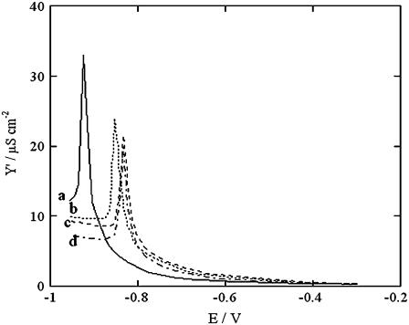
The procedure adopted for the incorporation of SLN consisted of scanning the applied potential from −0.300 to −0.950 V at 15 min intervals by a.c. voltammetry in aqueous 0.1 M KCl containing 0.7 μM SLN while recording the in-phase component, Y′, of the electrode admittance at 10 Hz. The Y′ versus E curves, shown in Fig. 1, exhibit a sharp peak that shifts progressively toward less negative potentials until it is stabilized in the proximity of −0.85 V after ∼1.5 h. This indicates that SLN incorporation into the tBLM practically attains equilibrium after this time.
FIGURE 1.
Y′ versus E plots at a tBLM in aqueous solution of 0.1 M KCl and 0.7 μM SLN, recorded after 15 (a), 45 (b), 90 (c), and 120 min (d) from SLN addition to the 0.1 M KCl solution.
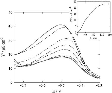
SLN incorporation in the tBLM may also be monitored indirectly by first incorporating valinomycin from its 30 nM solution in aqueous 0.1 M KCl. This K+-selective ionophore yields a Y′ versus E curve with a hump, due to K+ translocation across the lipid bilayer moiety of the tBLM. Upon addition of 0.7 μM SLN to this solution, repeated potential scans from −0.30 to −0.95 V yield Y′ versus E curves that decrease progressively, as shown in Fig. 2. The maximum of these curves attains a limiting value after ∼2 h (see the inset of Fig. 2).
FIGURE 2.
Y′ versus E plots at a tBLM in aqueous solution of 0.1 M KCl and 30 nM valinomycin, recorded (proceeding downward) after 0, 15, 38, 63, 87, 110, 135, and 159 min from the addition of 0.7 μM SLN. The inset shows a plot of the decrease, ΔY′, in the maximum of the Y′ versus E curves with respect to its initial value, against time.
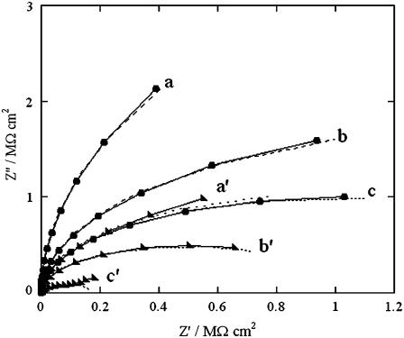
Impedance spectra of the tBLM, both in the absence of SLN and upon its incorporation, were recorded over the frequency range from 10−2 to 105 Hz at different potentials ranging from −0.3 to −0.9 V. Fig. 3 shows plots of the quadrature component of the electrochemical impedance, Z″, against its in-phase component, Z′, as obtained at three significant applied potentials in aqueous 0.1 M KCl on the same tBLM, both in the absence and in the presence of incorporated SLN. The resistance of the tBLM was estimated straightforwardly by fitting the curves in Fig. 3 to an equivalent circuit consisting of a resistance R and a capacity C in parallel (namely, an RC mesh simulating the tBLM), with in series the resistance RΩ of the aqueous solution. The dashed curves are fits of the curves to this equivalent circuit. Incidentally, an RC mesh yields a semicircle of diameter R on a Z″ versus Z′ plot. The fitting is satisfactory and provides accurate values of the “overall” resistance R of the tBLM under the different experimental conditions. In the tBLM of Fig. 3, the incorporation of SLN decreases the tBLM resistance from 11.7 to 2.1 MΩ cm2 at −0.500 V, from 3.6 to 1 MΩ cm2 at −0.700 V, and from 2 to 0.2 MΩ cm2 at −0.800 V, whereas the corresponding capacity varies only within the narrow range from 0.73 to 0.9 μF cm−2.
FIGURE 3.
Solid curves are Z″ versus Z′ plots at a tBLM in 0.1 M KCl at −0.500 V (a), −0.700 V (b), and −0.800 V (c) in the absence of SLN; a′, b′, and c′ are the corresponding plots after incorporation of SLN from its 0.7 μM solution. The dashed curves are fits of the corresponding solid curves to an equivalent circuit consisting of an RC mesh with the solution resistance, RΩ = 3 Ω cm2, in series. The R and C values of the mesh are 11.7 MΩ cm2, 0.73 μF cm−2 (a); 2.1 MΩ cm2, 0.77 μF cm−2 (a′); 3.6 MΩ cm2, 0.73 μF cm−2 (b); 1.0 MΩ cm2, 0.77 μF cm−2 (b′); 2.0 MΩ cm2, 0.73 μF cm−2 (c); and 0.2 MΩ cm2, 0.90 μF cm−2 (c′).
It should be noted that the Z″ versus Z′ plot in Fig. 3, often referred to as the Nyquist plot, ascribes a low weight to the high-frequency range of impedance data. To account for the high-frequency range in greater detail, a refined equivalent circuit is required. This will be examined in the Discussion section. At the present stage, the sufficiently accurate values of the overall resistance of the tBLM indicate unequivocally that the incorporation of SLN in the lipid bilayer moiety of the tBLM causes an appreciable increase in its conductivity. The lipid composition of the outer monolayer does not affect the increase in conductivity due to SLN incorporation to an appreciable extent. However, with a pure PC outer monolayer, after a few hours SLN causes a moderate increase in conductivity even at the most positive potentials investigated; moreover, after 1 day, it tends to shift the Y′ peak in Fig. 1 up to −0.6 V, ultimately destabilizing the lipid bilayer. In this respect, the presence of Chol was found to be important for the stability of the lipid bilayer in the presence of SLN.
To make an approximate estimate of the level of SLN incorporation in the tBLM, an SLN/lipid mixture molar ratio of 1:100 was rapidly dissolved in pentane and immediately spread on the surface of a 0.1 M KCl aqueous solution, allowing the pentane to evaporate. This operation was carried out in <5 min to avoid any SLN denaturation. A DPTL-coated mercury drop was then immersed in the solution to form the tBLM, and, after scanning the potential up to stabilization, as usual, its resistance was measured from the impedance spectrum. The resistance at −0.500 V was found to be equal to 3.0 MΩ cm2 and therefore relatively close to that, 2.1 MΩ cm2, obtained by incorporating SLN from its 0.7 μM aqueous solution.
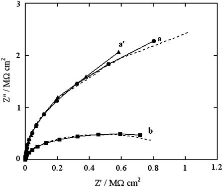
After verifying the increase in conductivity produced by SLN incorporation in a tBLM from aqueous 0.1 M KCl, analogous experiments were conducted in aqueous 0.04 M Na2H2ATP, whose pH was adjusted at 6.0 by addition of NaOH. At this pH, ATP is mainly present as HATP3−. This anion is known to be completely inpermeant to lipid bilayers, and its passage across biological membranes takes place only via certain integral proteins, such as the ATP:ADP antiporter. After recording the impedance spectra of the tBLM in the ATP solution at different applied potentials, the solution was diluted with an equal volume of an NaCl solution containing the same concentration of Na+ ions. The impedance spectra of the new solution were then recorded at the same applied potentials to verify the selectivity of any SLN pores to monovalent inorganic ions. Curves a and a′ in Fig. 4 are Z′ versus Z″ plots obtained at −0.580 V in the ATP solution in the absence and in the presence of SLN, respectively. The two plots are almost identical and yield an overall resistance of the tBLM of 7 MΩ cm2. Addition of the NaCl solution causes the resistance to drop to 1 MΩ cm2 (see curve b in Fig. 4). On the other hand, dilution of the ATP solution with the NaCl solution has no effect on the Z″ versus Z′ plot at −0.850 V (data not shown).
FIGURE 4.
Solid curves are Z″ versus Z′ plots at a tBLM in a pH 6 aqueous solution of 0.04 M Na2H2ATP at −0.580 V in the absence of SLN (a), after incorporation of SLN from its 0.7 μM solution (a′), and after subsequent dilution with an equal volume of an NaCl solution containing the same concentration of Na+ ions (b). The dashed curves are fits of the corresponding solid curves to an equivalent circuit consisting of an RC mesh with the solution resistance RΩ in series. The R, C, and RΩ values of the mesh are 7 MΩ cm2, 0.56 μF cm−2, 5 Ω cm2 (a), and (a′); and 1 MΩ cm2, 0.57 μF cm−2, 3.5 Ω cm2 (b).
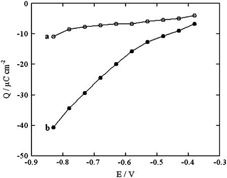
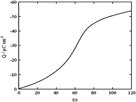
Analogous results were obtained by diluting the ATP solution with an equal volume of Na2HPO4, Na2SO4, or sodium oxalate solutions containing the same concentration of Na+ ion. Here too, an appreciable increase in conductivity was observed over the potential range from −0.45 to −0.65 V, but no change over the potential range from −0.80 to −1.00 V. Fig. 5 shows plots of the charge after potential jumps from a fixed initial value Ei = −0.380 V to progressively more negative values, Ef, on a tBLM incorporating SLN. The jumps were carried out in aqueous 0.04 M Na2H2ATP, both before and after addition of an equal volume of NaCl. Each potential jump was preceded by a rest time of 120 s at −0.380 V to restore the initial conditions. The charge was measured at a time of 120 s from the instant of the potential jump, when the charge due to the movement of ions across the tBLM had practically attained its maximum value. It is apparent that the presence of NaCl causes the charge to become more negative than does its absence, as the final potential becomes progressively more negative. The charge versus time curves after a potential jump from −0.300 V to −0.800 V are sigmoidal in shape, as shown in Fig. 6. The foot of the sigmoidal curve tends to become shorter if the potential jump is carried out immediately after keeping the tBLM at −0.800 V for a sufficiently long time.
FIGURE 5.
Q versus Ef plots at a tBLM incorporating SLN from its 0.7 μM solution in aqueous 0.04 M Na2H2ATP before (a) and after (b) addition of an equal volume of NaCl with the same concentration of Na+ ions. Q is the charge recorded upon stepping the potential from a fixed initial value Ei = −0.380 V to progressively more negative values E, after waiting 120 s before each potential jump.
FIGURE 6.
Charge versus time curve at a tBLM incorporating SLN from its 0.7 μM solution in aqueous 0.1 M KCl, after a potential jump from −0.300 to −0.800 V.
DISCUSSION
The potential difference across the lipid bilayer moiety of the tBLM (namely, the transmembrane potential) is close to zero when the electric potential applied to the whole mercury/(aqueous solution) interphase is close to −0.540 V (21,22) (see further). Therefore, the incorporation of SLN in a tBLM in contact with aqueous 0.04 M HATP3− does not increase the conductivity of the lipid bilayer moiety in the proximity of the transmembrane potential. Since it is well known that the bulky trivalent anion HATP3−cannot permeate through ion channels, it must be concluded that the SLN pores, if any, do not allow the translocation of monovalent cations across a lipid bilayer in the proximity of its transmembrane potential. On the other hand, the addition of chloride, phosphate, sulfate, or oxalate ions to the solution, while keeping the concentration of Na+ ions constant, increases the conductivity of the tBLM by almost an order of magnitude, the exact percentage decrease depending on the pristine resistance of the tBLM. At any rate, tBLMs incorporating SLN from ATP solutions were found to attain practically the same final resistance, upon chloride addition, independent of its pristine value, as expected with well-behaved lipid bilayers. This indicates unequivocally that, over the physiological range of transmembrane potentials, SLN forms channels that have a high selectivity for small inorganic anions but are practically impermeable to inorganic cations. The impermeability of vesicle membranes incorporating SLN to protons was reported by Smith et al. (6).
Further support to these conclusions comes from the two charge versus potential curves a and b in Fig. 5, recorded in aqueous 0.04 M HATP3− before and after addition of NaCl, respectively, while keeping the Na+ concentration constant. Under both experimental conditions, the SLN incorporated into the tBLM does not allow the flow of the bulky HATP3− anions across the lipid bilayer. In the absence of Cl− ions, the charge shows a very slight negative shift as the final potential passes from −0.380 to −0.780 V (see curve a in Fig. 5). In other words, the potential jumps from −0.380 V to progressively more negative potentials do not cause an appreciable flow of Na+ into the TEO hydrophilic spacer, despite the incorporation of SLN. Conversely, in the presence of Cl− ions, these are accumulated in the hydrophilic spacer at the initial potential of −0.380 V. The progressive jumps toward more negative potentials cause their gradual expulsion from the spacer, due to electrostatic repulsion. Their movement away from the electrode creates an electric potential difference, positive toward the electrode. This is compensated for by an electron flow along the external circuit toward the electrode, which is recorded as an additional negative capacitive current. This confirms that the SLN channels are substantially impermeable to Na+ ions at potentials positive of −0.750 V, whereas they are permeated by Cl− ions.
A further confirmation comes from the progressive decrease in the conductivity of valinomycin upon addition of SLN, shown in Fig. 2. This is due to the gradual formation of SLN channels, which increases the Cl− concentration within the hydrophilic spacer at the expense of the concentration of the K+ ions that are selectively shuttled by valinomycin. At −0.700 V the Y′ versus E curves tend to merge because the Cl− ions start to be electrostatically repelled from the spacer. The slightly sigmoidal curve in the inset of Fig. 2, which is a measure of the number of SLN channels as a function of time, denotes an initial induction period indicative of a nucleation of SLN monomers with channel formation. This is also apparent from the sigmoidal shape of the charge versus time curve in Fig. 6, which denotes a nucleation and growth of channel-forming aggregates (23).
Stefanova et al. (24,25) examined the properties of a Pi transporter present in the SR, which transports phosphate into the lumen of the SR, increasing the level of accumulation of Ca2+ in the SR by forming insoluble salts with Ca2+. It was, therefore, of interest to verify whether SLN channels exhibit some properties of this Pi transporter. The uptake of Pi in SR vesicles, after addition of ATP to activate Ca-ATPase, was reported to be depressed by millimolar concentrations of a number of phosphonocarboxylic acids (24). Moreover, the Pi transporter was reported to be stimulated by ATP and its effect was found to be higher at pH 5.3, where Pi is present as  than at pH 8.1, where it is present in the more negatively charged form
  (25). To verify whether the SLN channels exhibit these features, SLN was incorporated into the tBLM from its 0.7 μM solution in aqueous 0.04 M Na2H2ATP at pH 6, and the solution was then diluted with an equal volume of Na2HPO4, as usual.
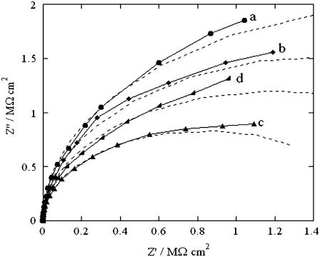
This dilution caused an increase in conductivity by ∼300%. The subsequent addition of 2.0 mM phosphonopropionic acid did not cause any detectable decrease in conductivity (data not shown). However, this test may not be particularly significant if the high concentration of ATP has an enhancing effect that counterbalances a possible depressing effect by the phosphonopropionic acid. To verify this point, SLN was slowly incorporated into a tBLM by the same procedure as in Fig. 1 from an aqueous solution of 5 × 10⁻² M NaH2PO4, whose pH was adjusted at 5.3 by a small addition of NaOH. After attaining equilibrium conditions for the incorporation of SLN, the  ion was found to cause only a modest decrease in the resistance of the tBLM (see Fig. 7). The subsequent addition of 0.5 mM ATP caused an appreciable decrease in resistance. The further addition of NaOH to adjust the solution pH at 8.5 caused the resistance to increase again. The latter test indicates that SLN channels exhibit some properties of the Pi transporter. A deeper investigation of the properties of the SLN channels will be the subject of a future note.
FIGURE 7.
Solid curves are Z″ versus Z′ plots at a tBLM in a pH 5.3 aqueous solution of 5 × 10⁻² M NaH2PO4 at −0.580 V in the absence of SLN (a), after incorporation of SLN from its 0.7 μM solution (b), after subsequent addition of 5 × 10⁻⁴ M Na2H2ATP (c), and after subsequent pH adjustment at 8.5 with 0.5 M NaOH (d). The dashed curves are fits of the corresponding solid curves to an equivalent circuit consisting of an RC mesh with a solution resistance RΩ = 8 Ω cm2 in series. The R and C values of the mesh are 3.8 MΩ cm2, 0.56 μF cm−2 (a); 3.2 MΩ cm2, 0.56 μF cm−2 (b); 1.7 MΩ cm2, 0.57 μF cm−2 (c); and 2.4 MΩ cm2, 0.56 μF cm−2 (d).
A more detailed analysis of the impedance spectra of tBLMs incorporating SLN from aqueous 0.1 M KCl was carried out by using the approach already adopted for the incorporation of valinomycin (13), outer membrane porin gene (OmpF) porin (14), and melittin (15) in the same tBLM. According to this approach, the sections of the whole electrified interface with different dielectric properties, namely the lipoic acid residue, the TEO hydrophilic spacer, the lipid bilayer moiety, and the aqueous solution adjacent to the tBLM, are represented by an equivalent circuit consisting of four RC meshes in series, one per each of these substructural elements. The elements of this equivalent circuit represent necessarily ideal lumped-constant properties, even though the K+ and Cl− ions are distributed in space across the tBLM, albeit nonhomogeneously. This equivalent circuit yields semicircles in a Z′ω versus Z″ω plot, where ω is the angular frequency. Naturally, when the relaxation times of the RC meshes are too close to each other, these semicircles are partially fused.
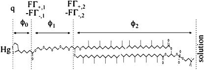
The R and C values of the different meshes were determined by fitting the experimental Z′ω versus Z″ω plots, which account satisfactorily for the low-frequency range, with the Autolab PGSTAT 12 software. The experimental dependence of the R and C values for the TEO and the lipid bilayer moieties upon potential was then simulated on the basis of a general electrochemical model of the tBLM. This model, described in detail in Becucci et al. (14,15), assumes that the charges within the tBLM are located as shown in Fig. 8: a free electronic charge density q on the surface of the mercury electrode, two charge densities FΓ+,1 and −FΓ−,1 at the boundary between the lipoic acid residue and the TEO moiety, and two charge densities FΓ+,2 and −FΓ−,2 at the boundary between the TEO moiety and the lipid bilayer. Here, Γ+,1, Γ+,2 and Γ−,1, Γ−,2 are surface concentrations of K+ and Cl− ions, respectively. The potential difference φt across the whole tBLM due to this charge distribution is expressed by the equation
 |
(1) |
In this equation, C0, C1, and C2 are, respectively, the “intrinsic” capacities of the lipoic acid residue, the hydrophilic spacer, and the lipid bilayer, as measured in the absence of ionophores, whereas φ0, φ1, and φ2 are the potential differences across these dielectric slabs. φ1 includes the dipole potential, χ1, of the hydrophilic spacer, which was estimated at ∼−0.250 V, negative toward the metal, on the basis of independent measurements (22).
FIGURE 8.
Schematic picture of the different substructures of a tBLM, with the primary structure of the DPTL thiolipid in contact with that of a PC molecule. The figure shows the potential differences across the different substructures and the proposed location of the different charges.
Recent data indicate that the extrathermodynamic absolute potential difference φt across the whole mercury|(aqueous solution) interphase is more positive than the potential E measured versus a saturated calomel electrode (SCE) by ∼0.250 V (21). Therefore, φt can be directly related to the applied potential E. In the absence of ionophores, the surface concentrations of K+ and Cl− vanish, and Eq. 1 becomes
 |
(2) |
By extracting q from Eq. 2 and replacing its expression in that of the transmembrane potential φ2, we obtain
 |
(3) |
Using the C0, C1, C2 values for the tBLM determined in Becucci et al. (13) in the absence of ionophores (i.e., C0 = 4 μF cm−2, C1 = 7 μF cm−2, C2 = 1 μF cm−2) and setting χ1 = −0.250 V, the transmembrane potential in the absence of ionic charges in the TEO moiety is approximately given by φ2 = 0.72 × (E/SCE + 0.500 V). Under these conditions, φ2 equals zero for E = −0.500 V/SCE (−0.540 V versus Ag|AgCl (0.1 M KCl)), as already stated, and its rate of change with E equals 0.72.
The incorporation of a channel-forming peptide or protein alters the conductance and capacity of the substructural elements with respect to their intrinsic values by an amount that will be denoted by an overbar. Roughly speaking, the alteration,  in the conductance of any given substructural element i is set equal to the rate of change with E of the current that flows to and fro along the element, and the alteration,
  in its capacity is set equal to the rate of change with E of the charge that accumulates at the boundary of the element, on its metal side. To this end, the currents, j+,2 and j−,2, which flow along the lipid-bilayer moiety and require the K+ and Cl− ions to surmount the corresponding potential energy barriers, are expressed by Butler-Volmer-like equations (14,15). Under equilibrium conditions (i.e., for j+,2 = j−,2 = 0), these equations reduce to Langmuir isotherms, with potential independent adsorption equilibrium constants, K+,2 and K−,2. Analogous expressions are used for the currents, j+,1 and j−,1, flowing along the hydrophilic spacer.
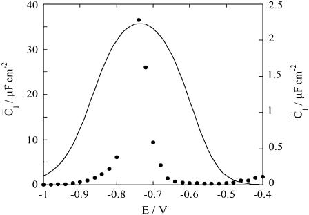
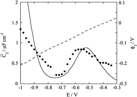
Figs. 9 and 10 show the potential dependence of the capacities,  and
and  ascribed to the hydrophilic spacer and to the lipid bilayer, as obtained by fitting the impedance spectra to the above equivalent circuit. To predict the shape of the curves in these figures on the basis of the model, use was made of the above values of χ1 and of the intrinsic capacities C0, C1, and C2. The equilibrium constants for the translocation of K+ and Cl− ions across the hydrophilic spacer were set equal to those, K+,1 = 5 × 10⁻³ and K−,1 = 5 × 10⁻³, providing the best fit to the impedance spectra of a tBLM incorporating both the channel-forming protein OmpF porin (14) and the channel-forming peptide melittin (15). In fact, the movement of these ions within the hydrophilic spacer is expected not to be affected by the molecules incorporated into the adjacent lipid bilayer. To fit the experimental impedance spectra, the equilibrium constants, K+,2 and K−,2, for the translocation of K+ and Cl− ions across the lipid bilayer were varied gradually.
FIGURE 9.
Plot of the capacity  of the hydrophilic spacer against E for a tBLM incorporating SLN from its 0.7 μM solution in aqueous 0.1 M KCl. Solid circles are experimental values, and the solid curve was calculated from the model for C0 = 4 μF cm−2, C1 = 7 μF cm−2, C2 = 1 μF cm−2, χ1 = −0.250 V, a = 50 V−1, Δ = −0.050 V, K+,1 = K−,1 = 5 × 10⁻³, K+,2 = 1 cm3 mol−1, and for K−,2 = 1 × 104 cm3 mol−1. The left-hand vertical axis refers to the solid circles, the right-hand one to the solid curve.
FIGURE 10.
Plot of the capacity  of the lipid bilayer against E for a tBLM incorporating SLN from its 0.7 μM solution in aqueous 0.1 M KCl. Solid circles are experimental values, and the solid curve was calculated from the model for the same values as in Fig. 8. The dashed curve is the curve of the transmembrane potential φ2 against potential calculated from the model.
The best fit was obtained for K+,2 and K−,2 equal to 1 cm3 mol−1 and 1 × 104 cm3 mol−1, respectively. Incidentally, the K+,2 value is much less than that, 3 × 105 cm3 mol−1, found for both OmpF porin and melittin. On the other hand, it is close to that, 3 cm3 mol−1, for the translocation of Cl− ion across the OmpF porin channel, which has a well-documented cationic selectivity. In principle, the equilibrium constants for ion translocation across the lipid bilayer should not depend on the nature of the incorporated ionophore, but only on the two phases separated by the bilayer. In practice, however, true equilibrium conditions are not attained even at the lowest frequencies adopted in the present a.c. measurements. Consequently, the differential capacity  which is estimated from the low-frequency range of the impedance spectrum, does not refer to true equilibrium conditions, and K−, 2 and K+,2 should be regarded as “pseudoequilibrium” constants.
To account for the low conductivity exhibited by the tBLM incorporating SLN at the most positive applied potentials, despite its appreciable anionic selectivity, it must be postulated that the SLN molecules assume a favorable orientation for channel formation only when moving toward more negative potentials. In other words, we must ascribe voltage-gated properties to SLN. These properties can be simulated by multiplying  and
and  by the probability of SLN assuming an orientation suitable for channel formation, as expressed by the well-known Boltzmann equation
 |
Here, Δ is the φ2 value at which the probability of a favorable orientation for channel formation is 0.5, and a is a parameter that measures the rate of increase of this probability.
An analogous approach was used to account for the voltage-gated properties of OmpF porin (14) and of melittin (15). By varying Δ and a gradually, a satisfactory fit to the  versus E curve in Fig. 10 was obtained for a = 50 V−1 and Δ = −0.050 V. The figure also shows a plot of the potential difference φ2 across the lipid bilayer moiety calculated from the model, namely the transmembrane potential. When the Cl− ions start to flow into the spacer, their accumulation shifts φ2 toward more negative values. This causes the zero transmembrane potential to be attained at an E value more positive than that, − 0.540 V, predicted in the absence of ions in the spacer. Then, as E is made progressively more negative, the gradual decrease in the Cl− concentration and the concomitant increase in that of K+ ions slows down the decrease of φ2 with decreasing E. Thus, the rate of decrease of φ2 with a decrease of E in Fig. 10 is about equal to 0.3, and, hence, smaller than the 0.72 value expected in the absence of ions in the spacer.
This situation is clearly different from that encountered with conventional BLMs, where it is the transmembrane potential φ2, and not the applied potential E, which is directly controlled. In practice, the hump of the  versus E plot, with a maximum at ∼−0.55 V, is due to the movement of Cl− ions across the lipid bilayer, whereas the rising section at potentials negative of −0.70 V is due to that of K+ ions. Fig. 9 shows the capacity
  of the hydrophilic spacer against the applied potential E and the corresponding curve calculated from the model. The two curves have a similar shape, with the maximum at ∼−0.75 V, but the calculated curve is much smaller than the experimental one. The potential dependence of the conductance,
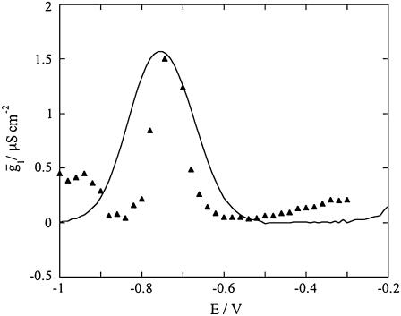
  across the hydrophilic spacer is shown in Fig. 11 and is similar to that exhibited by the corresponding capacity,
FIGURE 11.
Plot of the conductance  of the hydrophilic spacer against E for a tBLM incorporating SLN from its 0.7 μM solution in aqueous 0.1 M KCl. Solid triangles are experimental values, and the solid curve was calculated from the model for the same values as in Fig. 8 and for
To calculate the  versus E curve on the basis of the model, the backward rate constants,
  and
and  for the translocation of K+ and Cl− ions across the hydrophilic spacer are required, with the forward rate constants being given by
  and
and  Since this translocation is expected to be independent of the channel-forming protein incorporated into the lipid bilayer moiety, use was made of the
  and
and  values providing the best fit with a tBLM incorporating OmpF porin (14), namely,
  Agreement between experimental and calculated
  versus E curves is rather satisfactory. The conductance,
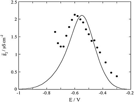
  across the lipid bilayer moiety is plotted against E in Fig. 12. To calculate the
  versus E curve from the model, the two further free parameters
  and
and  expressing the backward rate constants for the translocation of K+ and Cl− ions across the lipid bilayer, are required. In practice, the parameter
  may be varied over a broad range of values without affecting the calculated curve, because of the low permeability of SLN channels to K+ ions. The best fit is obtained by ascribing a value of 0.4 cm2 s−1 mol−1 to
FIGURE 12.
Plot of the conductance  of the lipid bilayer moiety against E for a tBLM incorporating SLN from its 0.7 μM solution in aqueous 0.1 M KCl. Solid circles are experimental values, and the solid curve was calculated from the model for the same values as in Fig. 8 and for
CONCLUSIONS
Both electrochemical impedance spectra and potentiostatic charge versus time curves indicate that incorporation of SLN molecules in a lipid bilayer yields channels selective toward inorganic anions and practically impermeable to monovalent inorganic cations, over the range of physiological transmembrane potentials. SLN forms channels when the transmembrane potential starts to become negative on the trans side of the lipid bilayer (see Fig. 5 and the φ2 versus E plot in Fig. 10). Only at transmembrane potentials more negative than ∼−120 mV on the trans side (see Fig. 10) do SLN channels allow the translocation of K+ and Na+ ions. This is also confirmed by the conductance of a tBLM in 0.04 M Na2H2ATP remaining unchanged at these negative potentials, upon addition of a NaCl solution of equal Na+ concentration.
It may be tempting to relate the property of SLN to allow the passage of phosphate and oxalate across a lipid bilayer in the presence of ATP to its regulatory function on SERCA1. In this connection, Odermatt et al. (1) reported that SLN stimulates maximal Ca2+ uptake rates. These authors measured Ca2+ uptake directly in microsomes expressing SERCA1 and coexpressing SERCA1 and SLN (and, therefore, probably in the absence of any Pi transporters of the SR) in a medium containing 5 mM potassium oxalate. Apparently, oxalate was not initially contained in the microsomes, so the increase in Vmax could be due to oxalate transport by SLN channels. Mutations in SERCA1 that diminish the regulatory function with PLN also diminish the regulatory function with SLN; it was, then, proposed that SLN fits into the site of PLN interaction with SERCA1a, albeit with a lower affinity (11). Incidentally, a direct interaction of SLN with Ca-ATPase is supported by an increased heat production by Ca-ATPase (26).
It may be tentatively hypothesized that, although the transmembrane domain of a SLN molecule is in contact with the lipid-facing surface of SERCA lined by M2, M4, M6, and M9, another face of the same molecule may interact with other SLN monomers giving rise to an anion-conducting oligomer. If this is the case, then this channel, in close contact with the SERCA, experiences the local transmembrane potential produced by the activity of this electrogenic pump. At high Ca2+ cytoplasmic concentrations, the SERCA pumping activity is expected to make the SR transmembrane potential locally positive on the luminal side; at the same time, the phosphate ion concentration on the cytoplasmic side of the pump increases, due to ATP hydrolysis. These two local changes may cooperate in moving the phosphate ions through the SLN channels from the cytoplasmic to the luminal side of the membrane. This phosphate translocation will then reduce the concentration of free Ca2+ ions, thereby increasing the level of Ca2+ accumulation in the lumen and enhancing the SERCA activity.
Acknowledgments
Thanks are due to Ente Cassa di Risparmio di Firenze for financial support through the PROMELAB project.
Editor: Thomas J. McIntosh.
References
- 1.Odermatt, A., S. Becker, V. K. Khanna, K. Kurzydlowski, E. Leisner, D. Pette, and D. H. MacLennan. 1998. Sarcolipin regulates the activity of SERCA1, the fast-twitch skeletal muscle sarcoplasmic reticulum Ca2+-ATPAse. J. Biol. Chem. 273:12360–12369. [DOI] [PubMed] [Google Scholar]
- 2.Mascioni, A., C. Karim, G. Barany, D. D. Thomas, and G. Veglia. 2002. Structure and orientation of sarcolipin in lipid environments. Biochemistry. 41:475–482. [DOI] [PubMed] [Google Scholar]
- 3.Buffy, J. J., B. A. Buck-Koehntop, F. Porcelli, N. J. Traaseth, D. D. Thomas, and G. Veglia. 2006. Defining the intramembrane binding mechanism of sarcolipin to calcium ATPase using solution NMR spectroscopy. J. Mol. Biol. 358:420–429. [DOI] [PubMed] [Google Scholar]
- 4.Hellstern, S., S. Pegoraro, C. B. Karim, A. Lustig, D. D. Thomas, L. Moroder, and J. Engel. 2001. Sarcolipin, the shortest homologue of phospholamban, forms oligomeric structures in detergent micelles and in liposomes. J. Biol. Chem. 276:30845–30852. [DOI] [PubMed] [Google Scholar]
- 5.Wawrzynow, A., J. L. Theibert, C. Murphy, I. Jona, A. Martonosi, and J. H. Collins. 1992. Sarcolipin, the proteolipid of skeletal muscle sarcoplasmic reticulum, is a unique, amphipathic, 31-residue peptide. Arch. Biochem. Biophys. 298:620–623. [DOI] [PubMed] [Google Scholar]
- 6.Smith, W. S., R. Broadbridge, J. M. East, and A. G. Lee. 2002. Sarcolipin uncouples hydrolysis of ATP from accumulation of CA2+ by the Ca2+-ATPase of skeletal-muscle sarcoplasmic reticulum. Biochem. J. 361:277–286. [DOI] [PMC free article] [PubMed] [Google Scholar]
- 7.Gayan-Ramirez, G., L. Vanzeir, F. Wuytack, and M. Decramer. 2000. Corticosteroids decrease mRNA levels of SERCA pumps, whereas they increase sarcolipin mRNA in the rat diaphragm. J. Physiol.. 524:387–397. [DOI] [PMC free article] [PubMed] [Google Scholar]
- 8.Gramolini, A. O., M. G. Trivieri, G. Y. Oudit, T. Kislinger, W. Li, M. M. Patel, A. Emili, E. G. Kranias, P. H. Backx, and D. H. MacLennan. 2006. Cardiac-specific overexpression of sarcolipin in phospholamban null mice impairs myocyte function that is restored by phosphorylation. Proc. Natl. Acad. Sci. USA. 103:2446–2451. [DOI] [PMC free article] [PubMed] [Google Scholar]
- 9.Babu, G. J., P. Bhupathy, N. N. Petrashevskaya, H. Wang, S. Raman, D. Wheeler, G. Jagatheesan, D. Wieczorek, A. Schwartz, P. M. L. Janssen, M. T. Ziolo, and M. Periasamy. 2006. Targeted overexpression of sarcolipin in the mouse heart decreases sarcoplasmic reticulum calcium transport and cardiac contractility. J. Biol. Chem. 281:3972–3979. [DOI] [PubMed] [Google Scholar]
- 10.Asahi, M., K. Kurzydlowski, M. Tada, and D. H. MacLennan. 2002. Sarcolipin inhibits polymerization of phospholamban to induce superinhibition of sarco(endo)plasmic reticulum Ca2+-ATPases (SERCAs). J. Biol. Chem. 277:26725–26728. [DOI] [PubMed] [Google Scholar]
- 11.Asahi, M., Y. Sugita, K. Kurzydlowski, S. De Leon, M. Tada, C. Toyoshima, and D. MacLennan. 2003. Sarcolipin regulates sarco(endo)plasmic reticulum Ca2+-ATPase (SERCA) by binding to transmembrane helices or in association with phospholamban. Proc. Natl. Acad. Sci. USA. 100:5040–5045. [DOI] [PMC free article] [PubMed] [Google Scholar]
- 12.Guidelli, R., G. Aloisi, L. Becucci, A. Dolfi, M. R. Moncelli, and F. Tadini Buoninsegni. 2001. New directions and challenges in electrochemistry. Bioelectrochemistry at metal/water interfaces. J. Electroanal. Chem. 504:1–28. [Google Scholar]
- 13.Becucci, L., M. R. Moncelli, R. Naumann, and R. Guidelli. 2005. Potassium ion transport by valinomycin across a Hg-supported lipid bilayer. J. Am. Chem. Soc. 127:13316–13323. [DOI] [PubMed] [Google Scholar]
- 14.Becucci, L., M. R. Moncelli, and R. Guidelli. 2006. Impedance spectroscopy of OmpF porin reconstituted into a mercury-supported lipid bilayer. Langmuir. 22:1341–1346. [DOI] [PubMed] [Google Scholar]
- 15.Becucci, L., R. Romero Léon, M. R. Moncelli, P. Rovero, and R. Guidelli. 2006. Electrochemical investigation of melittin reconstituted into a mercury-supported lipid bilayer. Langmuir. 22:6644–6650. [DOI] [PubMed] [Google Scholar]
- 16.Naumann, R., S. M. Schiller, F. Giess, B. Grohe, K. B. Hartman, I. Kärcher, I. Köper, J. Lübben, K. Vasilev, and W. Knoll. 2003. Tethered lipid bilayers on ultrahorizontal gold surfaces. Langmuir. 19:5435–5443. [Google Scholar]
- 17.Naumann, R., D. Walz, S. M. Schiller, and W. Knoll. 2003. Kinetics of valinomycin-mediated K+ ion transport through tethered bilayer lipid membranes. J. Electroanal. Chem. 550–551:241–247. [Google Scholar]
- 18.Schiller, S. M., R. Naumann, K. Lovejoy, H. Kunz, and W. Knoll. 2003. Archaea analogue thiolipids for tethered bilayer lipid membranes on ultrasmooth gold surfaces. Angew. Chem. Int. Ed. Engl. 42:208–211. [DOI] [PubMed] [Google Scholar]
- 19.Moncelli, M. R., and L. Becucci. 1997. A novel model of the hanging mercury drop electrode. J. Electroanal. Chem. 433:91–96. [Google Scholar]
- 20.Tadini Buoninsegni, F., R. Herrero, and M. R. Moncelli. 1998. Alkanethiol monolayers and alkanethiol/phospholipid bilayers supported by mercury: an electrochemical characterization. J. Electroanal. Chem. 452:33–42. [Google Scholar]
- 21.Becucci, L., M. R. Moncelli, and R. Guidelli. 2003. Ion carriers and channels in metal-supported lipid bilayers as probes of transmembrane and dipole potential. Langmuir. 19:3386–3392. [Google Scholar]
- 22.Moncelli, M. R., L. Becucci, and S. M. Schiller. 2004. Tethered bilayer lipid membranes self-assembled on mercury electrodes. Bioelectrochemistry. 63:161–167. [DOI] [PubMed] [Google Scholar]
- 23.Becucci, L., M. R. Moncelli, and R. Guidelli. 2003. Pore formation by 6-ketocholestanol in phospholipid monolayers and its interpretation by a general nucleation-and-growth model accounting for the sigmoidal shape of voltage-clamp curves of ion channels. J. Am. Chem. Soc. 125:3784–3792. [DOI] [PubMed] [Google Scholar]
- 24.Stefanova, H. I., J. M. East, and A. G. Lee. 1991. Covalent and non-covalent inhibitors of the phosphate transporter of sarcoplasmic reticulum. Biochim. Biophys. Acta. 1064:321–328. [DOI] [PubMed] [Google Scholar]
- 25.Stefanova, H. I., S. D. Jane, J. M. East, and A. G. Lee. 1991. Effects of Mg2+ and ATP on the phosphate transporter of sarcoplasmic reticulum. Biochim. Biophys. Acta. 1064:329–334. [DOI] [PubMed] [Google Scholar]
- 26.Mall, S., R. Broadbridge, S. L. Harrison, M. G. Gore, A. G. Lee, and J. M. East. 2006. The presence of sarcolipin results in increased heat production by Ca2+-ATPase. J. Biol. Chem. 281:36597–36602. [DOI] [PubMed] [Google Scholar]


