Abstract
A 250-GHz corrugated transmission line with a directional coupler for forward and backward power monitoring has been constructed and tested for use with a 25-W continuous-wave gyrotron for dynamic nuclear polarization (DNP) experiments. The main corrugated line (22-mm internal diameter, 2.4-m long) connects the gyrotron output to the DNP probe input. The directional coupler, inserted approximately midway, is a four-port crossed waveguide beamsplitter design. Two beamsplitters, a quartz plate and ten-wire array, were tested with output coupling of 2.5% (−16 dB) at 250.6 GHz and 1.6% (−18 dB), respectively. A pair of mirrors in the DNP probe transferred the gyrotron beam from the 22-mm waveguide to an 8-mm helically corrugated waveguide for transmission through the final 0.58-m distance inside the NMR magnet to the sample. The transmission-line components were all cold tested with a 248 ± 4-GHz radiometer. A total insertion loss of 0.8 dB was achieved for HE11 -mode propagation from the gyrotron to the sample with only 1% insertion loss for the 22-mm-diameter waveguide. A clean Gaussian gyrotron beam at the waveguide output and reliable forward power monitoring were achieved for many hours of continuous operation.
Index Terms: Corrugated waveguides, millimeter-wave directional couplers, millimeter-wave waveguides, transmission-line measurements
I. Introduction
The recent availability of multiwatt continuous wave (CW) power at 250 GHz for dynamic nuclear polarization (DNP) [1] and other diagnostic applications has created a need for efficient moderate power transmission-line and directional-coupler components. Fundamental mode WR-03 waveguide components (0.86 × 0.43 mm inside dimensions) are not practical due to high insertion losses of ≥ 8 dB/m. High transmission efficiencies at 250 GHz can be achieved by using overmoded waveguide (cross-sectional dimensions greater than a wavelength) or optical components. The most efficient overmoded waveguide mode is the HE11 mode in a corrugated waveguide [2]. This mode also ideally couples to a free-space Gaussian beam, which is optimum for achieving the smallest possible diffraction-limited spot sizes for maximizing power concentration or spatial resolution in an experiment.
Corrugated waveguide transmission lines are a well-established technology widely used with gyrotrons at lower frequencies. Some examples are the transmission lines at 110 GHz on the DIII-D tokamak [3], at 140 GHz on the ADSEX-upgrade tokamak [4], and at 84 and 168 GHz on the large helical device stellarator [5]. In this paper, we extend this technology to 250 GHz.
In addition to efficient transmission, a directional coupler is required in most experiments to monitor forward and reflected power. In high-power gyrotron transmission lines at lower frequencies, this is typically accomplished with small coupling holes in the mirror of a miter bend. Practical considerations due to the high-power levels and requirements for heat dissipation limit the coupling holes to linear arrays as used in the transmission lines at 110 GHz on DIII-D [6] and at 140 GHz on the Frascati tokamak upgrade [7]. To overcome the power coupling variations of a linear array when multiple modes are present in the transmission line, experiments with a two-dimensional array of holes in a copper film on a diamond substrate for heat dissipation have also been carried out [8]. In the research presented here, a quartz optical beam splitter, which is practical at moderate power levels, was implemented inside a straight section of corrugated transmission line to provide full beam cross-sectional coupling of both forward and reflected power. Thin wires stretched across the waveguide aperture in place of the quartz were also tested as an alternative beamsplitter.
II. Component Design
The layout and principal components of the 250-GHz transmission line for DNP experiments are illustrated in Fig. 1. From the gyrotron, the transmission line starts with a 22-mm-diameter 2.44-m-long corrugated waveguide with a beamsplitter directional coupler near the middle. At the output of this waveguide, a two-mirror optics unit focuses and directs the gyrotron beam into a smaller 8-mm-diameter 0.58-m-long helically tapped corrugated waveguide. The two mirrors consist of a spherical 50-mm-diameter 50-mm focal-length focusing mirror, and a 25-mm-square flat steering mirror. At the sample end of the 8-mm waveguide, a flat mirror 54.7° mitered waveguide bend directs the beam to the cryogenically cooled sample. A PTFE (Teflon) window is located in the 8-mm straight waveguide just before the miter bend. The 8-mm waveguide and sample are inside the bore of the magnet (not shown) for the DNP experiments. The 8-mm waveguide also serves the dual purpose of the central conductor of the coaxial line for the 30–300-MHz RF.
Fig. 1.
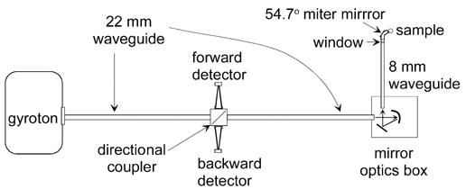
250-GHz transmission-line layout for DNP experiments.
A. Waveguide
The choice of the main waveguide diameter was based on an analysis of the gyrotron output. An internal Vlasov converter inside the gyrotron transforms the TE03 mode to a near Gaussian beam, launching it through a quartz window. Ray-tracing analysis of the Vlasov coupler predicts a slightly elliptical beam waist at the window with minimum and maximum diameters of 10.04 and 13.72 mm. A calculation of coupling such an elliptical beam to a circular corrugated waveguide HE11 mode as a function of waveguide diameter is shown in Fig. 2. The coupling efficiency is optimal with a waveguide diameter of approximately 18 mm. A somewhat larger waveguide diameter of 22.2 mm (7/8 in) was finally chosen after initial gyrotron output power measurements immediately outside the magnet Dewar side bore showed greater power output coupling using a larger diameter waveguide due to the presence of higher order modes. The compromise for the calculated coupling to the HE11 mode at this larger waveguide diameter is not significant, dropping only from 95% to 91%.
Fig. 2.
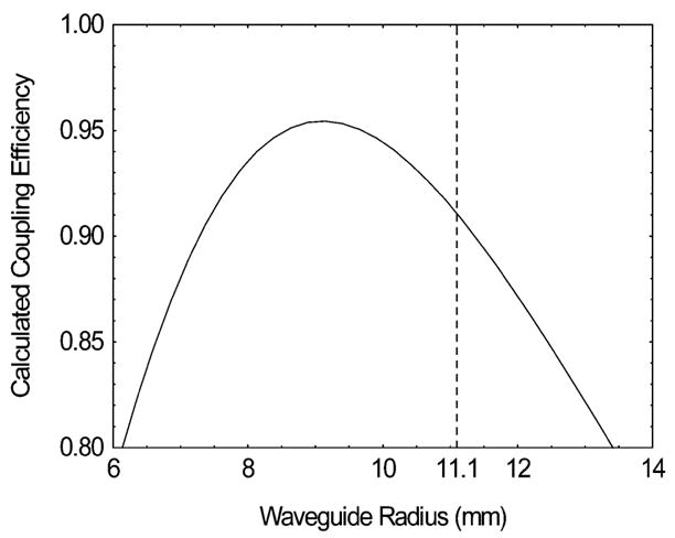
Calculated coupling efficiency of an elliptical Gaussian beam of 10.04 × 13.76 mm waste cross section to a circular waveguide HE11 mode.
The 22-mm-diameter corrugated waveguide was fabricated from many short aluminum tube sections with a wall thickness of 3.2 mm (1/8 in). The circumferential wall corrugations were 0.3-mm (0.25λ) deep and wide with a period of 0.4 mm (0.33λ). Two 0.254-m-long and 15 0.124-m-long waveguide sections and one 0.064-m-long directional coupler block were assembled with outer diameter clamps to achieve the desired waveguide length.
The 8-mm waveguide was fabricated from copper tubing with a short section of stainless-steel tubing welded in the middle to act as a cryogenic thermal break The internal corrugations were machined with a rifling tap having a pitch of 2.5 grooves per mm (3 perλ). The triangular groove depth was estimated to be between 1/4λ and 1/8λ. The total polarization rotation for propagating a 250-GHz beam through this waveguide due to the helical groove was estimated to be <3° using [9, eq. (2)]. After machining, internal and external surfaces of this waveguide were flash coated with silver and then gold to provide good electrical conductivity to the RF and protection from corrosion.
B. Directional Coupler
The directional-coupler design, illustrated in Fig. 3, uses crossed corrugated waveguides that are split along a diagonal of the crossed waveguide intersection to accommodate a beam-splitter. The beamsplitter thickness and index of refraction determine the degree of reflective coupling from the main waveguide direction to the side waveguide ports. The reflectivity of a beamsplitter, assuming no absorption, is given by the standard formula [10]
Fig. 3.
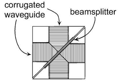
Design of the directional coupler fabricated from two corrugated waveguide corners that mate along the diagonal to hold the beamsplitter. One corner with a flat mirror along the diagonal would make a 90° waveguide miter bend.
| (1) |
where ρ is the surface reflection given by the Fresnel equations and δ is the phase difference between the beamsplitter front and back surfaces given by
| (2) |
For the two orthogonal E-field polarizations parallel and perpendicular to the plane of incidence (the plane of Fig. 3),
| (3) |
| (4) |
where, in the above equations, θi and θt are the angle of incidence and transmission, respectively, at the beamsplitter as related by Snell’s law of refraction (sin θi = n sin θt), n is the beamsplitter index of refraction, h is its thickness, and λo is the gyrotron beam wavelength in vacuum.
A low coupling factor is achieved by a beamsplitter minimum in reflectivity. At 250 GHz, fused quartz has an index of refraction of 1.955 [11] and for an incidence angle of 45° has a reflection minimum for a thickness of approximately 1 mm. Common microscope slides with this thickness and sufficient area (25 × 50 mm) to cover a 22-mm aperture at 45° are readily available and were used in the current experiments. Another advantage of this beamsplitter is that a visible laser beam can be introduced through a side port and its reflection off the beamsplitter can be aligned with the waveguide axis, facilitating downstream alignment of the transmission line and microwave optics.
A disadvantage of using a dielectric beamsplitter for signal coupling is that it is narrow-band. Narrow-band operation is not a limiting factor in this 250-GHz DNP experiment since only the narrow gyrotron frequency is transmitted, but stability is important for monitoring power. Small changes to the beamsplitter parameters, for example, due to thermal changes, could cause the coupling factor to drift. To overcome this potential limitation, experiments were carried out with thin wires stretched across the waveguide aperture as an alternative broad-band beamsplitter approach.
C. Coupler With Wires
The power scattered by a wire can be expressed as the product of its scattering cross section and the incident power density as
| (5) |
where σ has units of area and PD has units of power per unit area. In the following analysis, we will only consider the electric-field polarization normal to the wire axis because the scattering cross section is smaller for this orientation and we desire a small coupling factor. For an infinitely long small-radius wire such that the condition koa ≪ 1 is true, the scattering cross section is given by [12]
| (6) |
where Ψ is the angle between the incident beam and the normal to the wire axis and φ is the angle between the direction of the scattered signal and the plane containing the incident beam and wire. In our current coupler design for a wire stretched across the waveguide aperture perpendicular to the plane in Fig. 3, Ψ=0° and φ=90°. A 36-gauge wire with a = 63.5μm has a value σ⊥ = 5.8 × 10⁻³mm2 at 250 GHz (ko=5.24mm−1).
The power density of the HE11 mode inside a circular waveguide is best expressed in terms of the electric field density ED as
| (7) |
where is the impedance of free space and the electric-field density is given by [2]
| (8) |
where Po is the power of the gyrotron beam, A is the waveguide radius, r is the radius coordinate inside the waveguide, and Jo and J1 are Bessel functions.
According to (6), one wire will primarily backscatter the incident radiation (see the top of Fig. 4). An array of wires is needed to impart directionality to the scattered signal away from the backward direction. The sum of the scattered electric field for an array of wire scatters can be calculated with the aid of the grating equation [13]
Fig. 4.
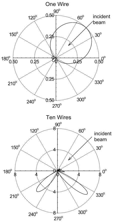
Scattered radiation patterns (Ps/Po × 103) at 250 GHz by one wire (36 gauge) and by a ten-wire array. The wires are arrayed with a spacing of 1/4λ along the vertical axis of this figure with the wire axis normal to the figure plane. The incident beam is 45° from normal to the wire array plane with a HE11 beam profile corresponding to corrugated waveguide with ka = 58.
| (9) |
where ξ is given by the grating equation as
| (10) |
and d is the spacing of the wires and
| (11) |
| (12) |
The wire spacing needs to be less than the wavelength to minimize the number of sidelobes in the radiation pattern. The radiation pattern for ten wires with a spacing of 0.25 λ is shown in the lower part of Fig. 4. The strongest radiation lobe is at approximately 83° to the incident beam with a scattering fraction of 0.0072 (−21.4 dB). The other strong radiation lobe is in the forward direction and does not contribute to the output coupling into the side port. The ten-wire side port coupling is not as optimal as with the quartz beamsplitter due to the slight angular offset, but it would be broad-band. Fig. 5 shows the ten-wire beamsplitter implemented on the diagonal face of the split four-port corrugated block for measurements described below.
Fig. 5.
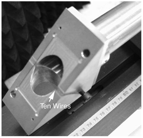
View of ten-wire 36-gauge beamsplitter stretched across the diagonal face of the corrugated four-port directional-coupler block.
III. Cold Tests
A 248-GHz heterodyne radiometer was used to test the transmission efficiency of the waveguide components with broad-band thermal radiation. The radiometer obtained from Millitech used a tripled 88.67-GHz Gunn local oscillator (LO) that was frequency stabilized to a 100-MHz crystal quartz reference. The IF amplifiers covered the 2–4-GHz range. A corrugated horn with an internal semiangle of 2.5° and an output aperture of 18 mm provided an HE11 mode field-of-view that was coupled to a 6.35-cm-long 22-mm-diameter corrugated waveguide section by a hollow acrylic plastic conical transition with an internal semiangle of 4°. A second 12.4-cm-long 22-mm-diameter waveguide section was fixed relative to the first with a gap of approximately 1 cm for insertion of a chopper. A photograph of this setup is shown in Fig. 6. The chopper permitted operation as a Dicke receiver [14] with lock-in amplifier phase-sensitive detection. The double-sideband (DSB) noise temperature was measured with a liquid-nitrogen-cooled thick (30 mm) pyramidal surfaced eccosorb1 black body to be approximately Tr = 11,000 K past the chopper at the end of the 22-mm-diameter waveguide. Though the theoretical measurement precision with this receiver, as given by , [15] is 0.2°C for 1-s integration time (t = 1s) and the full receiver DSB (B = 4 GHz), in practice, it was at least several degrees due to electronics drift.
Fig. 6.
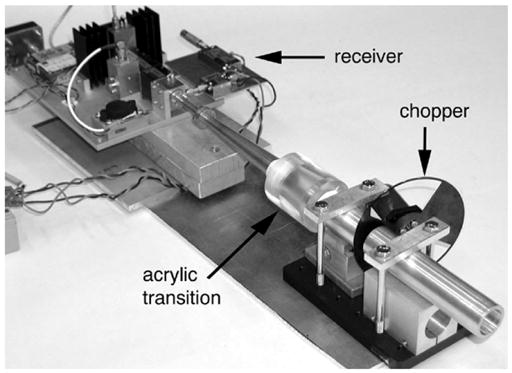
248-GHz heterodyne receiver used for cold-test measurements.
The transmission efficiency of the 250-GHz corrugated waveguide components was determined by measuring the increase in receiver noise temperature as the components were added to the end of the receiver-chopper assembly. The results for the 22-mm waveguide and the two versions of the directional coupler are shown in Fig. 7. The top plot (open circles) shows the transmission efficiency of the straight waveguide sections as they were built up to the full 2.4-m length without any directional coupler. A small linearly increasing insertion loss was observed that totaled 1% for the complete waveguide. This is probably an upper limit for HE11-mode transmission loss since it is likely that the receiver beam may have had some higher order mode content due to the acrylic transition and chopper waveguide gap.
Fig. 7.
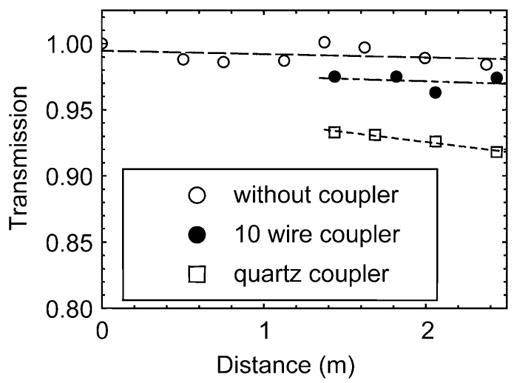
Cold-test transmission measurements of the 22-mm-diameter corrugated waveguide without and with two versions of the directional coupler.
In the next lower trace (solid circles) of Fig. 7, a directional coupler using a ten-wire beamsplitter, as described above, was inserted into the 22-mm waveguide 1.37 m from the receiver assembly. The measured loss of this coupler at the insertion location was 2.6%. In the lower trace (open squares), a directional coupler with a 1-mm-thick quartz beamsplitter was inserted in the same position and measured at a 6.8% insertion loss. Measurements of the noise temperature to the side port of the coupler for forward power coupling corresponded to a 1.6% and 6.3% coupling fraction for the wire and quartz beamsplitters, respectively. Therefore, some of the observed insertion loss is not coupled out to the monitoring port. A further measurement was made of the four-port corrugated waveguide block without a beamsplitter and was found to have an insertion loss of approximately 0.5%. Consequently, the difference between the observed insertion loss and side coupling can be accounted for by the discontinuity of the crossed waveguide in the four-port block.
The measured coupling fraction of 1.6% (−18 dB) with the ten-wire beamsplitter is 3 dB larger than the calculation above. This difference may be due to the approximate nature of the calculation for Koa ≪ 1 where, for the current case, Koa = 0.33.
The results for the coupler with the quartz beamsplitter can be understood with the aid of the calculations shown in Fig. 8. The quartz reflectivity is a sensitive function of frequency and thickness. The beamsplitter thickness was measured to be 0.94 ± 0.02 mm, one of the cases plotted in Fig. 8. Integrating the beam-splitter reflectivity over the detection bands of the receiver results in a reflectivity of 3.8 ± 2% for parallel polarization, the upper limit of which is close to the observed value. Rotating the quartz beamsplitter 90° on the waveguides axis to couple with the perpendicular polarization increased the measured coupling to 22%, which is also in agreement with the calculation of 22.2 ± 3% for a 0.94-mm-thick beamsplitter. For comparison, the case for a beamsplitter with a thickness of exactly 1 mm is also shown, which has a calculated parallel and perpendicular coupling of 0.24% and 1.7%, respectively. Polishing the quartz beamsplitter to a precise thickness can be used to achieve almost any desired coupling factor less than −3 dB at a specific frequency.
Fig. 8.
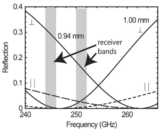
Calculated quartz (n = 1.995) beamsplitter reflectivity for a beam incidence at 45° for the two orthogonal polarization cases and two thicknesses.
The insertion loss of the two mirrors that transfer the millimeter-wave beam from the 22-mm waveguide to the 8-mm waveguide and the 8-mm waveguide was also measured and found to be 15 ± 3%. It is likely that most of this loss can be accounted for by nonoptimal threaded groove parameters and an elliptical distortion of the millimeter-wave beam caused by the spherical focusing mirror that is used at approximately 30° off-axis. Table I summarizes the cold-test insertion-loss measurements.
TABLE I.
250-GHz Gyrotron Beam Measurements
| Component | Insertion Loss |
|---|---|
| 22 mm waveguide, 2.44 mm long | 1% |
| Quartz coupler (6.3% coupling) | 6.8% |
| 10-wire coupler (1.6% coupling) | 2.6% |
| 4 port block w/o beamsplitter | 0.5% |
| Transfer mirrors and 8 mm waveguide | 15 ± 3% |
IV. Measurements with Gyrotron
The 22-mm-diameter corrugated waveguide with the quartz four-port directional coupler was tested with the CW gyrotron beam. Power was measured with a Model 362 Scientech calorimeter and mode patterns were obtained with thermal burn paper backed by a flat sheet of eccosorb to enhance absorption. The power measurements were not corrected for the actual millimeter-wave absorption by the calorimeter detector element [16]. Table II summarizes the results. The gyrotron power output was set to approximately 5 W for these measurements, which is adequate for the DNP experiments and allows very stable operation for periods of up to 100 h. Operation with output power up to 25 W is possible when long-term drift is not important.
TABLE II.
Cold-Test Insertion-Loss Measurement Results With 248 ± 4-GHz Radiometer
| Distance from Gyrotron Window (cm) | Burn Pattern | Power(W) |
|---|---|---|
| 30 (no waveguide) |

|
- |
| 38 |

|
4.5 |
| 100 |

|
- |
| 132 (after quartz coupler) |

|
- |
| 244 |

|
4.1 |
The top burn pattern was taken without any waveguide immediately outside the gyrotron magnet side port, approximately 30 cm from the gyrotron window. The irregular appearance of the beam indicates the presence of higher order modes. However, the nonlinear absorption properties of the thermal paper may exaggerate the content of higher order modes. In the next entry, a 38-cm-long section of the 22-mm waveguide was brought into near contact with the gyrotron window and aligned to maximize the power output. At this point, the beam is significantly distorted and elongated in the horizontal direction. The next measurement was made after 1 m of waveguide was added to the output of the gyrotron window. The beam now has evolved to two vertically separated hot spots. In the next entry, with 132 cm of waveguide, including the directional coupler, the beam has become a smaller elliptically elongated spot. Finally, at the output of the full waveguide, we have a single circular spot. Here, two burn paper exposures are shown. The short exposure shows a small circular spot. In the longer exposure, the small circular spot has been burned from black to a lighter shade of gray, making the outer regions of the beam visible, showing that the beam is circular over a large dynamic range. This suggests that the higher order gyrotron modes have been filtered from the beam by the 2.4-m-long transmission through the corrugated waveguide. A power measurement of 4.1 W was made at the waveguide output. This corresponds to an 11% loss relative to the first measurement of 4.5 W near the gyrotron output.
The forward output coupling of the quartz directional coupler was also tested with the calorimeter. A coupled fraction of 2.5% was measured. This is lower than the cold-test result because the quartz beamsplitter has a smaller reflectivity at the 250.55-GHz gyrotron frequency versus the two IF bands of the cold-test receiver (see Fig. 8). The gyrotron frequency was accurately established by harmonically mixing with a frequency counted and phase-locked loop (PLL)-regulated Gunn oscillator and performing a Fourier transform measurement of the IF frequency on a digital oscilloscope.
A 3-h test of the directional coupler was also carried out to determine thermal stability with the gyrotron beam. A detector diode in WR-3 waveguide was matched to the forward power monitoring port with a 2.5° corrugated horn from Millitech, a 4° hollow acrylic taper, and a short section of 22-mm dielectric waveguide similar to the setup of the 248-GHz radiometer described above. A thick pyramidal surfaced eccosorb dump blocked the reflection monitoring port opposite the forward port for this test. The harmonic frequency measurement receiver was used to simultaneously monitor the gyrotron power in the main beam after the directional coupler by intercepting a small part of the beam at a distance. Fig. 9 shows the results. The measured power levels are shown in Fig. 9(b) and the normalized ratio of these signals is plotted in Fig. 9(a). The coupling factor remains relatively stable over the 3-h period. Drifts in the detection electronics can explain the observed deviation of 0.8% in the coupling factor.
Fig. 9.
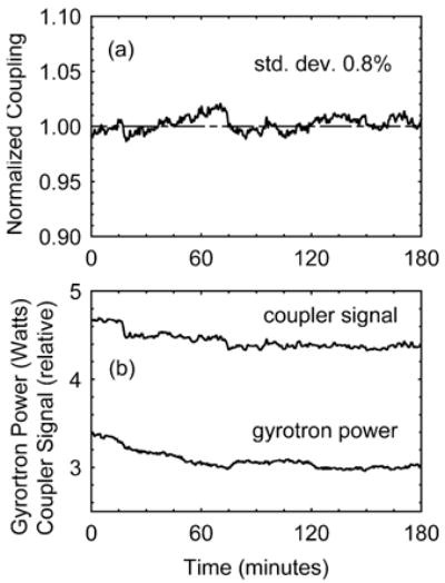
3-h CW test of the quartz directional coupler stability. (a) Normalized ratio of forward coupled signal. (b) Gyrotron power.
This directional coupler design will require careful matching of the detector diodes and/or isolation when both forward and backward detectors are simultaneously implemented because they view each other cross the beamsplitter.
V. Conclusions
A corrugated waveguide with a full cross-sectional directional coupler for use with a moderate power CW 250-GHz gyrotron for DNP experiments has been fabricated and successfully tested. Precise measurements of small insertion losses and coupling factors were made possible with the use of a wide-bandwidth radiometer, i.e., 248 ± 4 GHz, for cold testing rather than a coherent source that would have had standing-wave inaccuracies. The total transmission loss for an HE11 mode from the gyrotron to the sample was found to be approximately 0.8 dB over a total distance of 3 m with a directional coupler, an optical change in waveguide diameter, a Teflon window, and a miter bend. The actual loss was approximately 1.1 dB due to the presence of higher order modes in the gyrotron beam. However, with 5-W output at the gyrotron, 4 W can be readily coupled to the sample, which is more than adequate for the DNP experimental requirements. Most of the insertion loss of approximately 0.7 dB occurs in the 0.58-m-long 8-mm-diameter waveguide inside the DNP magnet probe and the associated two mirrors that transfer the gyrotron beam from the 22-mm-diameter waveguide. Future improvements in the performance of this section of the transmission-line system are possible by replacing the spherical mirror with an off-axis parabolic mirror and improved corrugation parameters. The main 22-mm-diameter 2.44-m-long waveguide with optimum corrugations was found to have an upper limit for HE11 mode transmission losses of only 1%.
The problem of monitoring forward power was solved with a four-port crossed corrugated waveguide with a beamsplitter. Two types of beam splitters were tested, i.e., a narrow-band thin quartz plate and a broad-band ten-wire scattering array. The quartz plate has the advantage that a visible laser beam can be superimposed on the millimeter-wave beam for alignment, but it has a disadvantage that it may be susceptible to frequency drift of the coupling factor under thermal loading by the gyrotron beam. The ten-wire scattering array is broad-band and the wires are good thermal conductors, potentially making the ten-wire array coupling factor more stable at higher power. Both beamsplitters cold tested generally as predicted and, in the current ~5-W CW gyrotron tests, the quartz beamsplitter did not reveal any problem with thermal drift. This directional coupler design along with the corrugated waveguide demonstrated here provide an efficient solution to the problem of transmitting and monitoring millimeter-wave beams at a frequency of 250 GHz.
Acknowledgments
The authors gratefully acknowledge many useful discussions with M. Shapiro, Massachusetts Institute of Technology (MIT), Cambridge.
Biographies
Paul P. Woskov (S’74–M’76–SM’99) received the Ph.D. degree in electrical engineering from the Rens-selaer Polytechnic Institute, Troy, NY, in 1976.
In 1976, he joined the Francis Bitter National Magnet Laboratory, Massachusetts Institute of Technology (MIT), Cambridge, where, since 1980 he has been with the MIT Plasma Science and Fusion Center. He is currently a Principal Research Engineer and Associate Division Head of the Plasma Technology Division. His principal interests include plasma diagnostics, fusion energy, millimeter-wave technologies, and environmental applications of plasmas and millimeter waves.
Dr. Woskov is a member of the American Physical Society, the American Chemical Society, and the American Association for the Advancement of Science.

Vikram S. Bajaj concurrently received the B.A. degree in biochemistry and M.S. degree in chemistry from the University of Pennsylvania, Philadelphia, in 2000, and is currently working toward the Ph.D. degree in physical chemistry at the Massachusetts Institute of Technology (MIT), Cambridge.
Since 2000, he has been a Research Fellow with the Francis Bitter Magnet Laboratory, MIT, where his research involves structure determination of biomolecules through solid-state nuclear magnetic resonance (NMR) and the development of DNP for sensitivity enhancement in NMR spectroscopy.

Melissa K. Hornstein (S’97) received the B.S. degree in electrical and computer engineering from Rutgers University, New Brunswick, NJ, in 1999, the M.S. degree in electrical engineering and computer science from the Massachusetts Institute of Technology (MIT), Cambridge, in 2001, and is currently working toward the Ph.D. degree in electrical engineering and computer science at MIT.
Since 2000, she has been a Research Assistant with the Plasma Science and Fusion Center, MIT. She has designed, developed, tested, and analyzed a novel submillimeter-wave second harmonic gyrotron oscillator, as well as being involved in other projects and applications in the millimeter and submillimeter regimes. Her research interests include novel microwave sources and amplifiers in the millimeter and sub-millimeter regimes and their applications, such as enhanced nuclear magnetic resonance spectroscopy via DNP.

Richard J. Temkin (F’94) received the B.A. degree in physics from Harvard University, Cambridge, MA, in 1966, and the Ph.D. degree in physics from the Massachusetts Institute of Technology (MIT), Cam-bridge, in 1971.
From 1971 to 1974, he was a Research Fellow with the Division of Engineering and Applied Physics, Harvard University. From 1974 to 1979, he was a Staff Member and an Assistant Group Leader with the National Magnet Laboratory, MIT. In 1980, he became Group Leader of the Gyrotron and Advanced Millimeter Sources Group, Plasma Fusion Center, MIT. Since 1985, he has been a Senior Research Scientist with the Physics Department, MIT. Since 1986, he has been Head of the Waves and Beams Division, Plasma Science and Fusion Center, MIT, where he currently serves as the Associate Director.

Robert G. Griffin received the B.S. degree in chemistry from the University of Arkansas, Fayetteville, in 1964, and the Ph.D. degree in physical chemistry from Washington University, St. Louis, MO, in 1969.
He performed post-doctoral research in physical chemistry with the Massachusetts Institute of Technology (MIT). In 1972, upon completion of his postdoctoral training, he assumed a staff position with the Francis Bitter National Magnet Laboratory, MIT. In 1984 he became a Senior Research Scientist, and was appointed to the faculty of the Department of Chemistry, MIT, in 1989. In 1992, he became Director of the Francis Bitter Magnet Laboratory (FBML) and is concurrently Director of the MIT–Harvard Center for Magnetic Resonance, where he had been Associate Director since 1989. He has authored or coauthored over 300 papers concerned with magnetic resonance methodology and applications of magnetic resonance (NMR and EPR) to studies of the structure and function of a variety of chemical, physical, and biological systems. Over the last decade, his research has focused on the development of methods to perform structural studies of membrane and amyloid proteins and on the utilization of high frequency (>100-GHz) microwaves in EPR experiments and in the development of DNP/NMR experiments at these frequencies.
Prof. Griffin has served on numerous advisory and review panels for the National Science Foundation and the National Institutes of Health (NIH).

Footnotes
Manufactured by Emerson and Cuming, Billerica, MA. [Online]. Available: http://www.emersoncuming.com
This work was supported by the National Institutes of Health under Grant EB-002061, Grant EB002804, and Grant EB002026. The work of V. S. Bajaj was supported by the Natural Sciences and Engineering Research Council of Canada under a Postgraduate Fellowship.
References
- 1.Bajaj VS, Farrar CT, Hornstein MK, Mastovsky I, Vieregg J, Bryant J, Elena B, Kreischer KE, Temkin RJ, Griffin RG. Dynamic nuclear polarization at 9 Tesla using a novel 250 GHz gyrotron microwave source. J Magn Reson. 2003;160:85–90. doi: 10.1016/j.jmr.2011.09.010. [DOI] [PubMed] [Google Scholar]
- 2.Doane JL. Propagation and mode coupling in corrugated and smooth-walled circular waveguides. In: Button KJ, editor. Infrared and Millimeter Waves. ch 5 Vol. 13. New York: Acadamic; 1985. [Google Scholar]
- 3.Callis RW, et al. IEEE Int Plasma Science Conf Rec. Abstract 02CH37340. 2002. The 6 MW, 110 GHz system for the DIII-D tokamak; pp. 294–294. [Google Scholar]
- 4.Leuterer F, et al. Experience with the ECRH system of ASDEX-upgrade. Fusion Eng Des. 2001;53:485–489. [Google Scholar]
- 5.Idei H, et al. Electron cyclotron heating scenario and experimental results on LHD. Fusion Eng Des. 2001;53:329–336. [Google Scholar]
- 6.Doane J, et al. In: Parker TJ, Smith SRP, editors. Quasi-Optic components in oversized corrugated waveguide for millimeter-wave transmission systems; 23rd Int. Infrared Millimeter-Waves Conf; Colchester, U.K. 1998. [Google Scholar]
- 7.Simonetto A, et al. Directional couplers-polarimeters for high-power corrugated waveguide transmission lines. Fusion Sci Technol. 2001;40:247–251. [Google Scholar]
- 8.Moeller CP, Lohr J, Doane JL. In: Temkin RJ, editor. The measured performance of a millimeter wave beam splitter; 23rd Int. Infrared Millimeter-Waves Conf. Dig.; San Diego, CA. 2002; pp. 307–308. [Google Scholar]
- 9.Woskov PP, Titus CH. Graphite millimeter-wave waveguide and mirror for high temperature environments. IEEE Trans Microw Theory Tech. 1995 Dec;43(12):2684–2688. [Google Scholar]
- 10.Born M, Wolf E. Principles of Optics. 5. sec. 7.6 New York: Pergamon; 1975. [Google Scholar]
- 11.Lamb JW. Miscellaneous data on materials for millimeter and submillimeter optics. Int J Infrared Millim Waves. 1996;17:1997–2034. [Google Scholar]
- 12.Ruck GT, Barrick DE, Stuart WD, Krichbaum CK. Radar Cross Section Handbook. ch 4 Vol. 1. New York: Plenum; 1970. [Google Scholar]
- 13.Young M. Optics and Lasers: Including Fibers and Optical Waveguides. 5. ch 6 New York: Springer; 2000. [Google Scholar]
- 14.Dicke RH. The measurement of thermal radiation at microwave frequencies. Rev Sci Instrum. 1946;17(7):268–275. doi: 10.1063/1.1770483. [DOI] [PubMed] [Google Scholar]
- 15.Tiuri ME. In: Radio Astronomy. ch 7 Krauss JD, editor. New York: McGraw-Hill; 1970. [Google Scholar]
- 16.Foote FB, Hodges DT, Dyson HB. Calibration of power and energy meters for the far infrared/near millimeter wave spectral region. Int J Infrared Millim Waves. 1981;2:773–782. [Google Scholar]


