Abstract
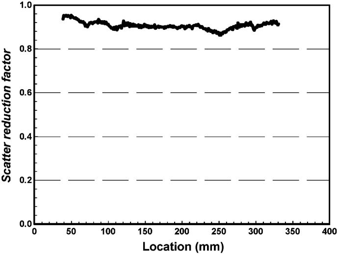
This paper describes and demonstrates an electronic collimation method, referred to as the alternate line erasure and readout (ALER) technique, for implementing slot-scan digital radiography technique with an amorphous silicon (a-Si) thin-film transistor (TFT) array based flat-panel detector. An amorphus selenium (a-Se) flat-panel detector was modified to implement the ALER technique for slot-scan imaging. A stepping-motor driven fore-collimator was mounted in front of an X-ray tube to generate a scanning X-ray fan beam. The scanning speed and magnification were adjusted to synchronize the fan beam motion with the image line readout rate. The image lines on the leading and trailing edges of the fan beam were tracked and alternately reset and read out, respectively. The former operation resulted in the erasure of the scatter signals accumulated in the leading edge image line prior to the arrival of the fan beam. The latter operation resulted in the acquisition of fan beam exposure data integrated in the trailing edge image line right after the fan beam passed. To demonstrate the scatter rejection capability of this technique, an anthropomorphic chest phantom was placed in PA position and scanned at a speed of 576 lines (8.0 cm)/s at 117 kVp and 32 mA. A tungsten bar is placed at the entrance side of the chest phantom to measure the scatter-to-primary ratio (SPR), scatter reduction factor (SRF), and contrast-to-noise ratio degradation factor (CNRDF) in the slot-scan images to evaluate the effectiveness of scatter rejection and the resultant improvement of image quality. SPR and CNRDF in the open-field images were also measured and used as the reference for comparison. A scatter reduction by 86.4 to 95.4% across lower lung and heart regions has been observed with slot-scan imaging. The CNRs have been found to be improved by a factor of 2 in the mediastinum areas over the open-field image as well.
Keywords: Digital radiography, flat-panel detector, scatter, scatter reduction, slot-scan
I. INTRODUCTION
INHERENT to the use of an area detector in projection radiography is the acceptance of scattered radiation as part of the image signal. This scatter component could degrade the low contrast performance through decreasing the contrast and contrast-to-noise ratio (CNR) for the objects to be detected or visualized [1]−[4]. Various techniques have been proposed and developed and investigated to reduce or reject the scattered radiation in radiographic practice over the decades, such as the collimation, air gap, and anti-scatter grid methods [5]−[7]. The anti-scatter grid method has been considered the most practical approach and widely used in many radiographic and fluoroscopic procedures with the conventional screen-film combinations or image intensifier based detector systems. When these analog detectors were replaced with digital detector systems, the use of anti-scatter grid (typically, a high-resolution stationary grid) was carried over in most cases for scatter rejection. The main advantage of using an anti-scatter grid is its simplicity. However, while it can be used to reject scattered radiation effectively, it also attenuates a substantial fraction of the primary X-rays (by as much as 30−50%), resulting in a significant loss of information carrying X-rays and an increase of relative noise level in the image [8]. To compensate for this attenuation of primary X-rays, the exposure must be increased to preserve the quantum noise level.
From 1970s, there have been numerous efforts to search for alternative techniques to reject scattered radiation without having to attenuate primary X-rays. Various slot-scan imaging techniques have been developed and investigated [9]−[25]. To implement slot-scan imaging with an area detector, a moving fore-collimator is usually placed between the X-ray source and the patient to form a narrow X-ray beam to scan the patient. X-rays detected within the fan beam areas are mostly primary X-rays plus a small component of radiation scattered within the fan beam. X-rays outside the fan beam area are purely scatter and are rejected by placing and moving a matching aft-collimator between the patient and image receptor to track the scanning fan beam. The two slots move synchronously and scan the object to be imaged. The advantage of the slot-scan technique is mainly its dose efficiency as the primary X-rays do not have to be attenuated as with the anti-scatter grid method. However, the system usually requires accurate and precise alignment of the fore- and aft-collimators with the X-ray tube focal spot. An additional issue with this two-collimator approach is the need to use a large (twice as big as the detector) and heavy aft-collimator to cover the entire detector area. The resulting bulkiness and weight makes it mechanically challenging to design and construct an aft-collimator that can be moved rapidly to track the fast scanning fan beam. This is especially the case for the large detectors (35.6 cm × 42.7 cm or 14 in × 17 in) used in chest imaging.
The use of linear detector array eliminates the need for a large and cumbersome aft-collimator. However, the detector itself still has to be physically moved in synchronization with the scanning fan beam.
We are currently developing a scan equalization digital radiography (SEDR) system with an a-Si/a-Se flat-panel detector. As the first stage of the SEDR development, we have developed an electronic aft-collimation method, referred to as the alternate line erasure and readout (ALER) technique, for implementing the slot-scan imaging technique. Instead of using a bulky and heavy aft-collimator, aft-collimation was achieved by modifying the readout electronics for the flat-panel detector to alter the line sequence in image readout. The ALER technique eliminates the need to construct and move a heavy and bulky aft-collimator or to physically move a linear array detector. In this paper, the principle and implementation of the ALER technique will be presented. The use of the ALER technique for slot-scan imaging and scatter rejection will also be demonstrated with images of an anthropomorphic chest phantom.
II. EFFECTS OF SCATTERED RADIATION
Both image contrast and noise properties are influenced by the scattered radiation through the scatter-to-primary ratio (SPR). In absence of scatter component, image contrast may be quantified by contrast ratio (CR), defined as the difference between the signal intensity of a low contrast object, I′P, and that of its surrounding area, IP, divided by the latter
| (1) |
The noise properties of the image signals are often characterized by the signal-to-noise ratio (SNR) which may be defined and computed as follows:
| (2) |
Since the detection and visualization of a low contrast object are influenced by both the image contrast and noise level, the CNR may be defined and computed to predict how well the object can be detected or visualized
| (3) |
To simplify the derivation, both primary and scattered X-rays are assumed to be mono-energetic but have different energies (mean energies for the primary and scattered X-ray spectra). For a quantum-limited digital radiographic system, image signals are assumed to be proportional to the detected photon number as follows:
| (4) |
| (5) |
where P and S are numbers of primary and scattered X-ray photons incident on and detected by a detector pixel, gP and gS are the gain factors that are approximately proportional to the photon energies and the energy absorption ratios for the primary and scattered X-ray photons.
In presence of a scatter component, IS, in both the low contrast object and its surrounding area, CRP, NP, SNRP and CNRP may be altered to CRP+S, NP+S, SNRP+S and CNRP+S as follows:
| (6) |
| (7) |
| (8) |
| (9) |
CRP+S, NP+S, SNRP+S, and CNRP+S are all proportional to their scatter-less counterparts: CRP, NP, SNRP, and CNRP with the proportion factors dependent upon IS/IP or SPR. Therefore, the SPRs are widely used to quantify the presence of scattered radiation in the image signals. The effects of scattered radiation are a degradation of the CR and an increase of the SNR as shown by (6) and (8), respectively. This latter is a result of increased image signals or detected photons. Although the scattered radiation does not contain useful information, it appears to reduce the fluctuation of the image signals. However, the detection and visualization of a low contrast object is related to the CNR and the object size rather than the CR or SNR alone by itself. Equation (9) shows that in presence of scatter, the CNR is degraded by a factor referred to as the CNR degradation factor (CNRDF) which may be computed to quantify the effects of scattered radiation on low contrast performance of an imaging system as follows:
| (10) |
III. MATERIALS AND METHODS
A. Electronic Aft-Collimation With a Flat-Panel Detector
With the ALER technique, instead of reading the image line by line as with the original design of the flat-panel detector, the image lines are reset and read in synchronization with the scanning X-ray fan beam. During slot-scan imaging, the image line on the leading edge of the fan beam is reset to erase the scatter component accumulated prior to the arrival of the fan beam while the line on the trailing edge is read out to acquire the image signals integrated following the exposure and passing of the scanning fan beam. This resetting and readout cycle is repeated and synchronized to the projection of the scanning fan beam. As with most slot-scan imaging techniques, a small portion of in-fan-beam scatter component would be left in the image signals read out. Furthermore, incomplete erasure of the leading edge lines would also contribute to the residual scatter component in the image signals.
The flat-panel detector studied in this investigation is an a-Se based unit with an active area of 35.6 cm × 42.7 cm (14 in × 17 in) and a pixel size of 139 μm. The active area of the detector is divided into a 2560 × 3072 array of image elements. The TFT gate-line driven electronics are laid along two short sides of the detector panel while the readout electronics are along two long sides. The readout signals are digitized into 14-bits image data. For the regular operation with commercial flat-panel detector, image signals were read out line-by-line following a short X-ray exposure. With the ALER technique, scatter erasure and image readout are alternately performed while the X-ray fan beam is scanning across the detector (Fig. 1).
Fig. 1.
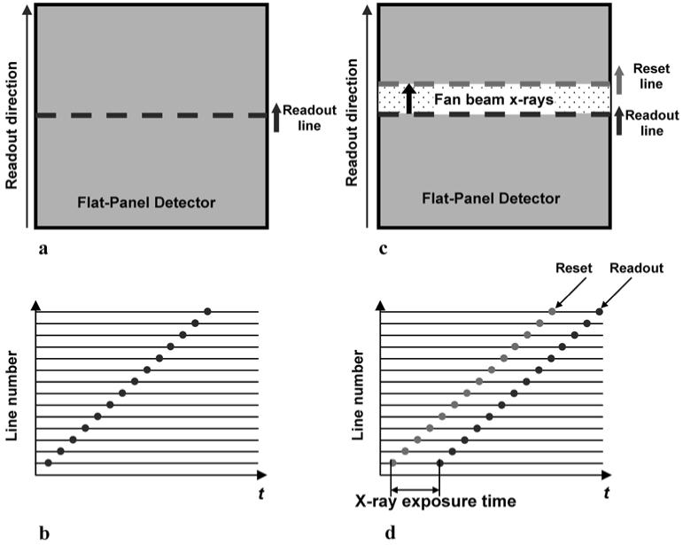
Conventional post-exposure line-by-line readout scheme (a), (b) in a commercial flat-panel digital radiography systems. ALER technique alternatively reset the leading edge line and readout the trailing edge line synchronized with the scanning fan beam X-rays was demonstrated (c), (d) for slot-scan digital radiography implemented with a flat-panel detector.
Unlike actual image readout, the resetting of an image line for scatter erasure can be done within a very short time. Thus, this process can be integrated with the readout of an image line without actually increasing the readout time. We modified the readout schemes of the flat-panel detector by introducing an additional “reset line” selecting signal during the “readout line” erasing period. Although the total scanning time may take several seconds, the effective exposure time for each image line is significantly shorter. For instance if the total scanning time is 4.44 s, the effective exposure time for each image line would be 4.44/35.6 = 125 msec for 1-cm–wide fan beam to scan a 35.6-cm (14-in)-wide detector. The modification of read-out scheme is nondestructive. Thus, the system can be switched to operate in either slot-scan or open-field imaging mode. This feature allows us to compare the properties of slot-scan and open-field imaging using same detector in the future.
B. Experimental Setup
The experimental setup for slot-scan digital radiography with the ALER technique is shown in Fig. 2. The plot at right-hand side illustrates how system rejects scattered radiation originating within the phantom by resetting the image line at leading edge of the fan beam, hence avoiding the need for an aft-collimator. The signal profile represents image signal of each pixel in scanning direction at the moment when fan beam arrives. Signals outside fan beam are purely contributed by scattered radiation. Signals inside fan beam are contributed by primary and in-slot scattered radiation. Following the readout, the image line at trailing edge of the fan beam is reset and then start to accumulate scattered radiation while fan beam moves away.
Fig. 2.
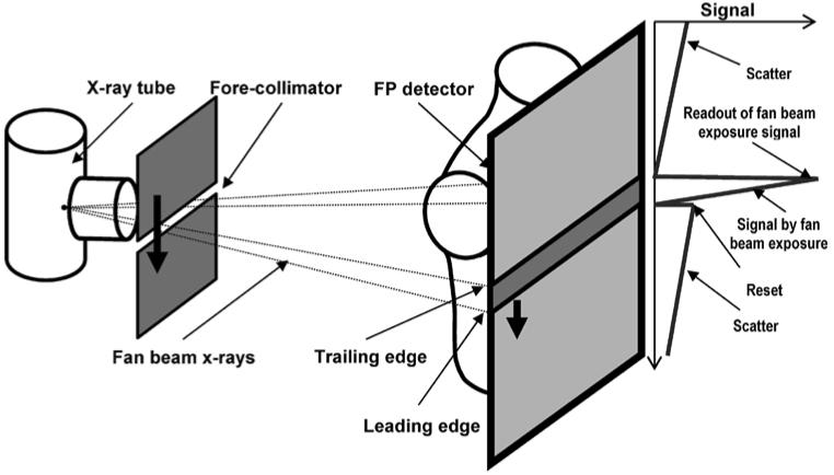
Experimental setup for slot-scan digital radiography with ALER technique. The image line on the leading edge is reset followed by readout of the trailing image line in tracking the motion of the projected fan beam. The former allows the scatter component accumulated prior to arrival of the fan beam to be erased while the latter results in readout of the image signals accumulated following the fan beam exposure.
The flat-panel detector is mounted in “Landscape” orientation (35.6 cm in vertical direction and 42.7 cm in horizontal direction) so that the electronic aft-collimation is in parallel with the scanning fan beam X-rays. This arrangement is appropriate with chest phantom images in our study. The fore-collimator consists of a 3-mm-thick tungsten plate with a 3.6-mm-wide slot oriented in horizontal direction. It was mounted on a motorized translational stage and moved to produce a scanning X-ray fan beam vertically. An alternative approach to generate the scanning fan beam is to rotate the X-ray tube about the focal spot with the fore-slot mounted on it. The fan beam has a projected width of 18 mm on the detector when the collimator is positioned for 5× magnification. Thus, the separation between the leading and trailing edge lines is estimated to be 129 lines.
A three-phase generator/console (Polyphos 50, Siemens Medical Systems) and an X-ray tube (P125/20/50 CR-65, Siemens Medical Systems) were installed and used for this study. The flat-panel detector, X-ray tube and the fore-slot collimator were mounted on a 122 cm × 244 cm (4 ft × 8 ft) optical bench with air suspensions. The source-to-detector distance (SID) was maintained at 183 cm (72 in). Large focal spot of 1.2 mm was selected. The penumbra caused by the finite focal spot size and the edges of fore-slot was evaluated and the integrated primary signal drop was estimated to be 5%.
C. Image Acquisition
An anthropomorphic chest phantom in PA position was imaged with the ALER technique at 117 kVp and 32 mA with and without the fore-collimator. No anti-scatter grid was used. The image acquired with fore-collimation resulted in a slot-scan image. The image acquired without fore-collimation is equivalent to an open field image. The two images were compared to evaluate the scatter rejection ability of the slot-scan imaging technique implemented with the ALER method. The open field image was acquired with the ALER aft-collimation in operation and the fore-collimator removed to ensure that both the slot-scan and open field images were acquired with the same X-ray technique (tube current and effective exposure time). With the fore-collimator removed, the space between the leading and trailing image lines (for signal erasure and readout, respectively) defined a virtual X-ray fan beam which scanned the detector. Primary X-rays outside this fan beam were erased and not recorded while those within were actually integrated and read out. However, in contrast to slot-scan imaging, scattered radiation from the entire field of view rather than just the fan beam was recorded along with the primary X-rays. Thus, the result is an image equivalent to an open-field image acquired with the same tube current and effective exposure time as with the slot-scan image. The exposure of the scanning fan beam to each image line lasted for about 222 ms, corresponding to an effective exposure of 7.1 mAs at 32 mA. The exposure is higher than those used in clinical procedures but used in our experiments to minimize the fluctuations in measurements.
For quantitative evaluation, a 3-mm-thick tungsten bar was placed horizontally in front of the chest phantom across the lower lung and heart regions. The tungsten bar blocks the primary X-ray photons from reaching the detector. Images were acquired with and without the tungsten bar to measure the scatter distribution, IS(x), and the total (open field or primary plus scatter) image signal, IP+S(x), respectively. Measurements were performed along five image lines in the middle of the tungsten bar and then averaged vertically to reduce fluctuations. The primary signals, IP(x), were computed as the difference between the total and scatter signals, IP+S(x) – IS(x). Linear image data were used in these measurements. Dark current and gain corrections were applied to the data prior to image processing.
Following the measurement of IS(x), and IP+S(x), and IP(x), the position dependent SPR, scatter reduction factor (SRF) and CNRDF, SPR(x), SRF(x), and CNRDF(x), were computed as follows:
| (11) |
To directly quantify the scatter rejection ability of the slot-scan imaging technique, a quantity referred to as the SRF can be defined and computed as follows:
| (12) |
where the superscripts “of” and “ss” refer to open-field and slot-scan, respectively. The SRF measures the fraction of scatter removed from the open field image signal.
To demonstrate the improvement of the image quality with slot-scanning imaging, the CNRDFs were computed as a function of the horizontal position using (10) for both the slot-scan and open field images
| (13) |
To estimate gS/gP, the mean energies of 120 kVp primary X-rays transmitted through 20 cm of tissue and the scattered X-rays were estimated to be 69.3 and 55.4 keV, respectively [26], [27]. The ratio of the scatter photon energy to the primary photon energy was then multiplied with the ratio of the detector absorption ratio at 55.4 keV to that at 69.3 keV to obtain an estimation of gS/gP. The ratio of the detector absorption ratio at 55.4 keV to that at 69.3 keV was calculated to be 1.426 for selenium layer with a thickness of 1 mm [28].
IV. RESULTS
Fig. 3 shows the chest phantom images acquired at 117 kVp with [Fig. 3(a)] and without [Fig. 3(b)] fore-collimation for comparison of effectiveness of scatter rejection with ALER technique. Fig. 3(a) was obtained with the slot-scan imaging method, implemented with the ALER technique, while the lower image corresponds to an open-field image without any scatter rejection technique applied. Images were acquired with same exposures and displayed with same window and level settings. The overall darker and dull appearance of the open field image was due to the presence of a large amount of scattered radiation which increased the signal size (hence, darker) and degraded the image contrast (hence, duller) significantly. With much of scattered radiation rejected, the slot-scan image has lower (brighter) signal value and higher image contrast. The difference is especially pronounced in the heavily attenuated regions. The lines across the lower lung and heart regions indicate where the tungsten bar was placed for scatter measurement. The total image signals IP+S and scatter IS measured across the lower lung and heart regions are plotted in Figs. 4 and 5, for the slot-scan and open-field images, respectively. Scatter in lightly attenuated regions are generally higher than those in heavily attenuated regions for both slot-scan and open-field images, however, scatter in the slot-scan images were substantially reduced over those in the open-field images. The primary signals IP, computed from the total image signals and scatters, are plotted in Fig. 6 for both slot-scan and open-field images. The two plots matched with each other very well, indicating that the slot-scan technique as implemented with the ALER method could preserve the primary X-rays while efficiently rejecting scattered radiation.
Fig. 3.
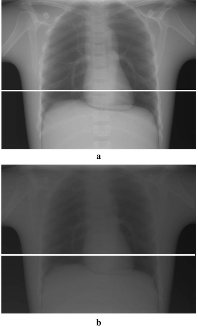
(a) Slot-scan and (b) open-field images of an anthropomorphic chest phantom shown in inverted log scale with same window and level settings. A bright line (in the image shadow of tungsten bar) across the lower lung and heart regions indicates where the scatter measurement took place.
Fig. 4.
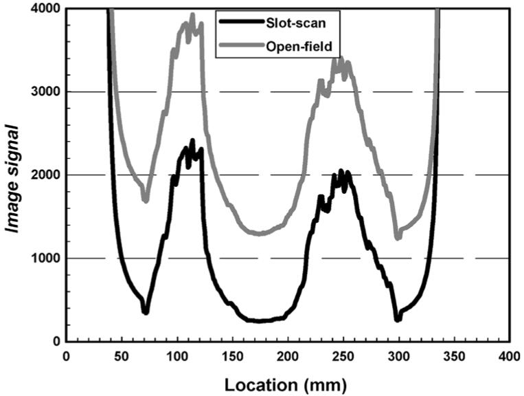
Total (primary plus scatter) image signals measured across the lower lung and heart regions in the slot-scan and open-field images of a chest phantom.
Fig. 5.
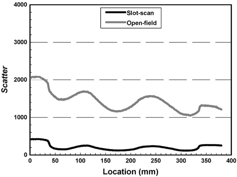
Scatter components measured across the lower lung and heart regions in the slot-scan and open-field images of a chest phantom.
Fig. 6.
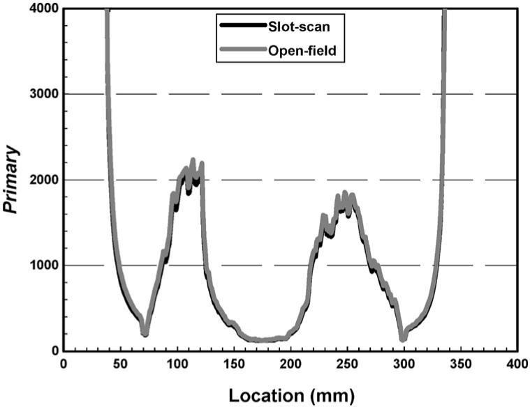
Primary signals measured across the lower lung and heart regions in the slot-scan and open-field images of a chest phantom.
The scatter-to-primary ratios (SPRs) are plotted for the slot-scan and open-field images for comparison in Fig. 7. It is clear that the SPRs were significantly higher in heavily attenuated regions than those in lightly attenuated regions even though the scatter behaved reversely. This is due to the fact that the primary signals were relatively lower in heavily attenuated regions compared to those in lightly attenuated regions. The SPRs were substantially reduced in the slot-scan image over those in the open-field image. The scatter reduction factors (SRFs) are plotted in Fig. 8 to demonstrate the effectiveness of scatter rejection with the slot-scan imaging technique (implemented with the ALER method). A reduction by 86.4% to 95.4% was observed. The SRF values in lightly attenuated regions (lung field) are slightly lower than those in heavily attenuated regions (mediastinum, chest wall). The SRF varied smoothly along the horizontal line over which the measurements were made. The use of a narrower slot is expected to result in even lower SPRs for even more effective scatter rejection [29].
Fig. 7.
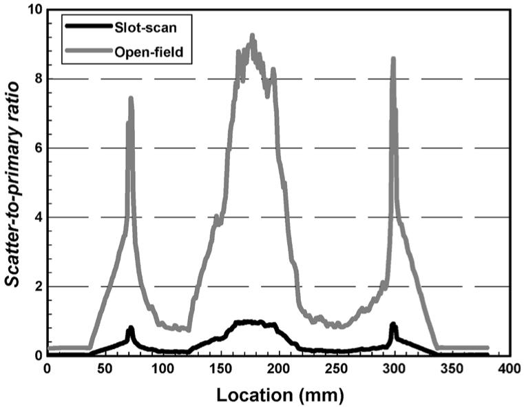
SPRs measured across the lower lung and heart regions in the slot-scan and open-field images of a chest phantom.
Fig. 8.
SRF measured across the lower lung and heart regions in the slot-scan over open-field images of a chest phantom.
The CNR degradation factors for slot-scan and open-field images are plotted and compared in Fig. 9. The factors were higher for the slot-scan images, therefore indicating a significant improvement in the low contrast performance through scatter rejection. Although the slot-scan images performed better than the open-field images in all regions studied, the improvement was more pronounced in the heavily attenuated mediastinum regions. Using the CNRDF as the measure, the image quality is roughly improved by a factor of 2 in the mediastinum regions while lower in the lung areas. This may be due to the fact that the image quality was high to start with in the lung areas (due to much lighter attenuation).
Fig. 9.
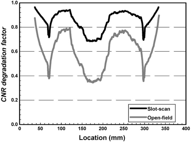
CNRDF measured across the lower lung and heart regions of a chest phantom plotted and compared for slot-scan and open-field images.
V. DISCUSSION AND CONCLUSION
We have demonstrated the feasibility to implement the ALER technique for electronic aft-collimation with a flat-panel detector. The ALER technique was used to implement the slot-scan imaging technique to effectively reject scattered radiation without attenuating the primary X-rays and without using a bulky, heavy aft-collimator. The slot width can be easily alternated for different applications. A reduction of scatter by 86.4%−95.4% across lower lung and heart regions was observed with an 18-mm slot width used in this study. Exposure is expected to be reduced by 30%−50% with slot-scan imaging as no attenuation of primary X-rays is required as with the anti-scatter grid method. Implementation of the ALER technique with a flat-panel detector requires some modifications of the readout electronics and some re-programming of the readout sequence. This is intrinsically much simpler than constructing and operating a physical aft-collimator which would be excessively heavy and bulky for scanning.
There are several concerns related to slot-scan digital radiography. First, the potential motion artifacts due to pulmonary or heart might be appeared on the images acquired. Samei et al. have indicated that the motion in slot-scan images would be less impacted than that of open-field systems [30]. Our current experimental unit takes about 4.44 s to scan the entire detector with a vertical scan length of 35.6 cm while the new detectors with readout time about or less than 1 s are available commercially (Prixium-4600 with 1.25-s readout, Trixell, France; GR17 with 0.5-s readout, Anrad Corporation, Canada). The total exposure time for slot-scan could be longer than that of conventional open-field imaging approach, however, the “open-field equivalent” exposure time is much shorter, therefore, the motion blurring effect should be insignificant. FPD with faster readout time may reduce motion artifacts, however, there is a potential lag or ghost problem, therefore, a reasonable detector readout speed need to be determined for slot-scan digital radiography.
Second, the X-ray tube loading may impact the applications of slot-scan digital radiography. The tube loading used to be an issue in the past with a narrower scanning beam width. Narrower slot width results in better scatter rejection performance [29], however, it requires higher X-ray tube current in order to maintain sufficient X-ray exposure. So does FPD with faster readout. To choose a proper slot width and scanning speed becomes a key factor for determining X-ray tube current while preserving image qualities. A 4-cm fan beam width has a comparable effectiveness for scatter rejection when compared with anti-scatter grid [29]. For chest radiography performed at 120 kVp with anti-scatter grid, exposures of 2 to 4 mAs for PA positions and 10 to 20 mAs for Laterals are typically required for a median size patient. The exposures can be reduced by 30 to 50% for slot-scan radiography when a anti-scatter grid is not in use, resulted in exposures of 1.2−2.4 mAs for PA positions and 6−12 mAs for Laterals when 40% dose saving is considered. If, for instance the FPD readout time is 1 s, scanning fan beam X-ray width set to be 2 cm, effective exposure time of 46.5 ms (1000 ms times 2/42.7) is achievable to scan a 17-in detector panel. With X-ray tube current of 500 mA to be selected, exposure of 23.3 mAs is achievable. This is adequate even for imaging a large size patient. The drawback of the slot-scan is the X-ray dose efficiency only about 4.68% in this case (23.3 mAs/500 mAs). By doubling the fan beam width, the tube loading can be reduced by 50% and the X-ray dose efficiency will be increased to 9.36%. Therefore, there is a trade-off in selecting imaging parameters between the readout speed (or slot width) and the tube loading.
We have demonstrated the image quality improvement with slot-scan imaging by measuring and comparing the CNR degradation factors and comparing with those of open-field imaging. In addition to reduction of the SPRs, it is equally important to achieve sufficiently high photon flux at the detector input. Exposure modulation techniques are being developed and investigated to further improve the CNR by applying higher photon flux to heavily attenuated regions (e.g., mediastinum, abdomen) while reducing the photon flux to lightly attenuated regions (e.g., lung). Exposure equalization, along with slot-scan imaging, could result in uniform image quality for detection and visualization of low contrast objects, despite the spatial variation of attenuating properties in the patient body. Furthermore, the exposure equalization could result in more uniform scatter distribution and SPRs. This may help equalize the image quality over the entire field of view.
Acknowledgments
This work was supported in part by the National Institute of Biomedical Imaging and Bioengineering under Research Grant EB00117 and in part by the National Cancer Institute under Research Grant CA51248 and Research Grant CA104759.
REFERENCES
- 1.Niklason LT, Sorenson JA, Nelson JA. Scattered radiation in chest radiography. Med. Phys. 1981 Nov.8:677–681. doi: 10.1118/1.595027. [DOI] [PubMed] [Google Scholar]
- 2.Barnes GT. Contrast and scatter in X-ray imaging. Radiographics. 1991 Mar.11:307–323. doi: 10.1148/radiographics.11.2.2028065. [DOI] [PubMed] [Google Scholar]
- 3.Boone JM, Lindfors KK, Cooper VN, III, Seibert JA. Scatter/primary in mammography: comprehensive results. Med. Phys. 2000 Oct.27:2408–2416. doi: 10.1118/1.1312812. [DOI] [PubMed] [Google Scholar]
- 4.Floyd CE, Baker JA, Lo JY, Ravin CE. Measurement of scatter fractions in clinical bedside radiography. Radiology. 1992 June;183:857–861. doi: 10.1148/radiology.183.3.1584947. [DOI] [PubMed] [Google Scholar]
- 5.Sorenson JA, Floch J. Scatter rejection by air gaps: an empirical model. Med. Phys. 1985 May;12:308–316. doi: 10.1118/1.595690. [DOI] [PubMed] [Google Scholar]
- 6.Neitzel U. Grids or air gaps for scatter reduction in digital radiography: a model calculation. Med. Phys. 1992 Mar.19:475–481. doi: 10.1118/1.596836. [DOI] [PubMed] [Google Scholar]
- 7.Shaw CC, Wang T, Gur D. Effectiveness of antiscatter grids in digital radiography: a phantom study. Investigative Radiology. 1994;29:636–642. doi: 10.1097/00004424-199406000-00007. [DOI] [PubMed] [Google Scholar]
- 8.Liu X, Shaw CC. Effects of anti-scatter grid on measurement of detector characteristics. Med. Phys. 2002 July;29:1342. [Google Scholar]
- 9.Jaffe C, Webster EW. Radiographic contrast improvement by means of slit radiography. Radiology. 1975 Sep.116:631–635. doi: 10.1148/116.3.631. [DOI] [PubMed] [Google Scholar]
- 10.Sorenson JA, Nelson JA. Investigations of moving-slit radiography. Radiology. 1976 Sep.120:705–711. doi: 10.1148/120.3.705. [DOI] [PubMed] [Google Scholar]
- 11.Barnes GT, Brezovich IA, Witten DM. Scanning multiple slit assembly: a practical and efficient device to reduce scatter. Am. J. Roentgenol. 1977;129:497–501. doi: 10.2214/ajr.129.3.497. [DOI] [PubMed] [Google Scholar]
- 12.Sorenson JA, Nelson JA, Niklason LT, Jacobsen SC. Rotating disk device for slit radiography of chest. Radiology. 1980 Jan.134:227–231. doi: 10.1148/radiology.134.1.7350609. [DOI] [PubMed] [Google Scholar]
- 13.Rudin S, Bednarek DR. Improved contrast in special procedures using a rotating aperture wheel (RAW) device. Radiology. 1980 Nov.137:505–510. doi: 10.1148/radiology.137.2.7433683. [DOI] [PubMed] [Google Scholar]
- 14.Sashin D, Sternglass EJ, Slasky BS, et al. Diode array digital radiography: initial clinical experience. Am. J. Roentgenol. 1982;139:1045–1050. doi: 10.2214/ajr.139.6.1045. [DOI] [PubMed] [Google Scholar]
- 15.Slasky BS, Sashin D, Horton JA, et al. Digital radiography of the chest by self-scanning linear diode arrays. Acta Radiologica. 1987;28:461–466. [PubMed] [Google Scholar]
- 16.Plewes DB, Vogelstein E. A scanning system for chest radiography with regional exposure control: practical implementation. Med. Phys. 1983 Sep.10:655–663. doi: 10.1118/1.595333. [DOI] [PubMed] [Google Scholar]
- 17.Plenkovich D, Sorenson JA, Kruger RA. Scatter rejection by electronic collimation. Med. Phys. 1986 Mar.13:158–163. doi: 10.1118/1.595940. [DOI] [PubMed] [Google Scholar]
- 18.Chotas HG, Floyd CE, Jr., Dobbins JT, III, Lo JY, Ravin CE. Scatter fractions in AMBER imaging. Radiology. 1990 Dec.177:177. doi: 10.1148/radiology.177.3.2244003. [DOI] [PubMed] [Google Scholar]
- 19.Holdsworth DW, Gerson RK, Fenster A. A time-delay integration charge-coupled device camera for slot-scanned digital radiography. Med. Phys. 1990 Sep.17:876–886. doi: 10.1118/1.596578. [DOI] [PubMed] [Google Scholar]
- 20.Wagenaar DJ, DiBianca FA, Tenney CR, Vance JE, Reed MSC, Wilson DW, Dollas A. A computer-controlled X-ray imaging scanner using a kinestatic charge detector. Rev. Sci. Instrum. 1990 Feb.61:701–711. [Google Scholar]
- 21.Barnes GT, Wu X, Sanders PC. Scanning slit chest radiography: a practical and efficient scatter control design. Radiology. 1994 Feb.190:525–528. doi: 10.1148/radiology.190.2.8284410. [DOI] [PubMed] [Google Scholar]
- 22.Jing Z, Huda W, Walker JK. Scattered radiation in scanning slot mammography. Med. Phys. 1998 July;25:1111–1117. doi: 10.1118/1.598433. [DOI] [PubMed] [Google Scholar]
- 23.Mainprize JG, Ford NL, Yin S, Tumer T, Yaffe MJ. A slot-scanned photodiode-array/CCD hybrid detector for digital mammography. Med. Phys. 2002 Feb.29:214–225. doi: 10.1118/1.1446108. [DOI] [PubMed] [Google Scholar]
- 24.Besson GM, Koch A, Tesic M, et al. Design and evaluation of a slot-scanning full-field digital mammography system. 2002 Proc. SPIE Physics of Medical Imaging Conf. 4682:457–458. [Google Scholar]
- 25.Kroft LJM, Geleijns J, Mertens BJA, Veldkamp WJH, Zonderland HM, Roos A. Digital slot-scan charge-coupled device radiography versus AMBER and bucky screen-film radiography for detection of simulated nodules and interstitial disease in a chest phantom. Radiology. 2004 Apr.231:156–163. doi: 10.1148/radiol.2311030206. [DOI] [PubMed] [Google Scholar]
- 26.Birch RM, Marshall GM, Adran GM. Catalogue of Spectral Data for Diagnostic X-Rays. Hospital Physicists Association; London, U.K.: 1979. [Google Scholar]
- 27.Chan HP, Doi K. Physical characteristics of scattered radiation in diagnostic radiology—Monte-Carlo simulation studies. Med. Phys. 1985 Mar.12:152–165. doi: 10.1118/1.595771. [DOI] [PubMed] [Google Scholar]
- 28.Hubbell JH, Seltzer SM. Tables of X-Ray Mass Attenuation Coefficients and Mass Energy-Absorption Coefficients 1 keV to 20 MeV for Elements Z = 1 to 92 and 48 Additional Substances of Dosimetric Interest. Nat. Inst. Standards Technol. Rep. NISTIR 5632; Gaithersburg, MD: 1995. [Google Scholar]
- 29.Liu X, Shaw CC, Altunbas MC, Wang T. Scan equalization digital radiography (SEDR): implementation with a flat-panel detector. Proc. SPIE (Physics of Medical Imaging Conf.) 5745:1112–1120. [Google Scholar]
- 30.Samei E, Saunders RS, Lo JY, et al. Fundamental imaging characteristics of a slot-scan digital chest radiographic system. Med. Phys. 2004 May;31:2687–2698. doi: 10.1118/1.1783531. [DOI] [PubMed] [Google Scholar]


