

Abstract
The purpose of the present study was to develop a set of equations that can be employed to remove the inertial effect introduced by the movable platform upon which a person stands during a slip induced in gait; this allows the real ground reaction force (GRF) and its center of pressure (COP) to be determined. Analyses were also performed to determine how sensitive the COP offsets were to the changes of the parameters in the equation that affected the correction of the inertial effect. In addition, the results were verified empirically using a low friction movable platform together with a stationary object, a pendulum, and human subjects during a slip induced during gait. Our analyses revealed that the amount of correction required for the inertial effect due to the movable component is affected by its mass and its center of mass (COM) position, acceleration, the friction coefficient, and the landing position of the foot relative to the COM. The maximum error in the horizontal component of the GRF was close to 0.09 body weight during the recovery from a slip in walking. When uncorrected, the maximum error in the COP measurement could reach as much as 4 cm. Finally, these errors were magnified in the joint moment computation and propagated proximally, ranging from 0.2 to 1.0 Nm/body mass from the ankle to the hip.
Keywords: ground reaction force, center of pressure, foot landing, slip distance, fall
INTRODUCTION
In recent decades, support surface perturbations have become a common approach employed to elucidate the mechanisms for the control of balance (Ferber et al., 2002; Horak et al., 1997; Horak and Nashner, 1986; Macpherson et al., 1989; Nashner, 1980; Tang et al., 1998), to assess one's postural stability limitations (Henry et al., 1998; Maki, 1998), and to induce motor adaptation for fall prevention(Bhatt et al., 2006; Horak, 1996; McIlroy and Maki, 1995; Nashner, 1976; Pavol et al., 2002). These types of perturbations can be applied to a standing person by moving the support surface platform with an actively controlled, motorized mechanism (Pagnacco et al., 2000; Preuss and Fung, 2004; Robinson et al., 1998). Alternatively, in a passive mechanism, the platform can be allowed to move only in reaction to one's own motion. When it rests atop a set of low friction linear bearings, upon computer-controlled release, the platform is free to move during sit-to-stand or in gait (Bhatt et al., 2005; Pai, 1999). The former approach affords the experimenter precise control of the various parameters of the perturbation, such as the peak velocity and total displacement, applied to the subjects in stimulus-response studies (Maki, 1998; Robinson et al., 1998). The latter can be used to mimic real-life situations in which adaptive control for recovery acquired through training can reduce the peak slip velocity under similar low friction conditions (Bhatt et al., 2006).
In both approaches, the inertial effect of the moving platform affects the values of the ground reaction forces (GRF). The GRF's are used to determine resultant joint moments and the mechanical causes of the response (Pai, et al., 2006). Methods for the removal of the inertial effect from the GRF recording have been established with the active, motorized system, where the force transducers are instrumented between the motor and the standing person (Pagnacco et al., 2000; Preuss and Fung, 2004; Robinson et al., 1998). In contrast, little has been developed for the passive mechanism with slips induced under low friction conditions.
It has been noted that slip distance is one of the key factors that influences the outcome of a slip, either recovery or fall (Brady et al., 2000). Therefore, the moving platform needs to be able to travel a sufficient distance in order to reproduce falls in a laboratory environment. In those motorized designs where force transducers or force platforms were a part of the movable component, the displacement was often limited (Ferber et al., 2002; Muller and Redfern, 2004; Pagnacco et al., 2000; Preuss and Fung, 2004; Robinson et al., 1998; Tang et al., 1998). To produce the large magnitudes of translation at high accelerations that are observed during slips (Bhatt et al., 2005) can substantially increase the level of design difficulty and the cost for a motorized setup. This dilemma can be resolved with the use of a passive design where a low friction support base can afford very long slip distances at a reasonable cost. When the non-moving support base rests on top of two force platforms, the real GRF acting on the person can be derived by eliminating the inertial effect produced by the moving component.
The purpose of the present study was, therefore, to develop a set of equations suitable for removing the inertial effect of the moving component from the recorded GRF, such that the real GRF acting on the person can be determined during a long slip. Sensitivity analyses were then performed to determine the relative importance of the parameters in these equations in correcting the inertial effect. Finally, these results were verified empiricallyby employing a stationary object, a pendulum, and human subjects.
METHODS
1. Correction of Inertial Effect
The general features of such a device include a non-movable component and a movable component. The non-movable component can be built on a long beam resting on two force platforms, which enables long travel distance for the movable component. The movable component may consist of a simple flat plate mounted on low friction bearings interfacing with the beam, which contains the low friction tracks and is anchored on the force platforms. Our equations to determine the real GRF and its center of pressure (COP) acting on the person during perturbations are based on this general configuration.
The non-movable component
In this two-dimensional analysis, the non-movable component has a two-point support connecting with two separate force platforms (Fig.1-a). The force components and the COP of the GRF acting on system A (Fig.1-b), which includes both the person and the movable component, Fx2, Fz2, and x, can be derived directly from force platform measurements based on the equilibrium conditions:
| (1) |
| (2) |
Where Hb, is the thickness of the non-movable component, and FPx1, FPz1, x1, FPx2, FPz2, and x2, are the X- and Z-components of the force and the COP that can be derived directly from the measurements of the force platforms 1 and 2, respectively. Here, m0 represents the mass of the non-movable component; g, the acceleration due to gravity. This effect (m0g) of the non-movable component does not change during the same trial or from trial-to-trial; thus it can be eliminated experimentally through re-calibration by subtracting it as a constant offset.
Fig. 1.

Free-body diagrams of (a) the non-movable component in the inertial reference frame with an origin at point O, (b) system A, which includes the foot and the movable component, and (c) the movable component of the slip inducing device. The foot and movable component travel the same motion in the X direction. The forces acting on system A, Fx2 and Fz2, can be derived from measurements from the two force platforms, FPx1, FPx2, FPz1, and FPz2. Because the connections between the non-movable component and the force platforms are point and hinge contact, moments are negligible. The horizontal component of the acceleration of the movable component is ax. Not shown in (c) are xcoM and xcoP, the X-coordinates of the movable component's center of mass (COM) and the corrected center of pressure (COP) acting on the person with respect to the origin, O. The COP offset (u−v) represents the amount of correction needed by relating the measured COP, v, to the corrected COP, u, with respect to the COM. X and Z axes represent the directions of anteroposterior and vertical, respectively.
The movable component
The corrected force components of the GRF and its COP acting on the person, Fx1, Fz1, and xCOP, can be determined by taking into account the inertial effect of the movable component (Fig.1-c).
| (3) |
| (4) |
| (5) |
Substituting Eqs (3) and (4) into (5), the following expression can be obtained.
| (6) |
where, ax is the horizontal acceleration of the movable component; m, the mass of the movable component; xCOM, the X-coordinate of the movable component's COM with respect to the origin, O; and H1 and H2, the relative vertical distances of the force Fx1 and Fx2 to the COM, respectively; u and v, the respective COP of the Fz1 and Fz2 relative to the COM. The absolute corrected COP is presented as:
| (7) |
Because the movable component's COM is a constant, xCOM can be determined by the motion capture system during perturbation; likewise, the horizontal velocity and ax can be calculated by numerical differentiation. Unlike the non-movable component, correction of the inertial effect for the movable component cannot be done through a re-calibration method such as treating it as an offset.
2. Sensitivity Analysis
We used the term (v−u) to represent the COP offset, by relating the measured COP, v, to the corrected COP, u, with respect to the COM. Notably, u also provides a measurement of the landing position of the foot at its initial contact with the movable component. To investigate the factors which affect v, Eq (6) was rewritten as:
| (8) |
Eq (8) has shown that v was determined by ax, m, H1, H2, Fx1, Fz1, and u. To evaluate the impact of each factor on the COP offset, (v−u), we derived the following expression (see online supplement for detail):
| (9) |
For simplification, we introduced the friction coefficient,μ = Fx2 / Fz2, and another parameter, σ = H1 / H, to depict the vertical position of the COM (Fig. 1). Eq (9) can then be rewritten as,
| (10) |
H is H1+H2, the vertical dimension of the movable component from its surface to its contact support with the non-movable component below.
It is noteworthy that when the mass or acceleration of the movable component is negligible or reduces to zero, Eq (10) will be:
| (11) |
This COP offset will be negligible when either H or Fx2 is very small.
In line with Eq (8), seven factors impact the COP offset in Eq (10). We take the partial derivatives of Eq (10) with respect to each factor to construct the sensitivity coefficient of each item, Si, as follows:
| (12) |
To reduce the complexity within this 7-dimensional space, we confined our sensitivity analyses to be close to a set of measurements that were used in our laboratory, in which the regular values for H, σ, and m were 5.8 cm, 0.28, and 2.7 kg, respectively. Their variations were also systematically investigated. We have observed in our numerous experiments that the varying ranges for other variables are: ax ≈ −10 to 20 m/s2, u ≈ −0.15 to 0.15 m about the COM, and Fz1 = 500 to 900 N. We inspected two possible values for μ, 0.02 and 0.04.
3. Experimental Verification
A device used to induce a slip was constructed with the non-movable component consisting of a metal beam structure (21 × 30 × 250 cm) anchored to the top of two rectangular force plates (Fig. 1-a). The movable component consisted of a metal plate (0.6 × 30 × 65 cm) and its support system. This plate can either be locked for regular walking trials or released to simulate a slip. The friction coefficient of the device was consistently less than 0.04 within its maximum travel distance of 1.8 m. A second set of such devices was available to study bilateral behavior.
Three sets of experiments were conducted for verification purposes. One set employed a 24-kg stationary object being placed on top of the movable component, which was pulled horizontally with a weight of 1kg (Fig. 2-a). Another set of experiment used an 8.4-kg metal object that was suspended from a special steel frame located on the movable component. The object swung as a pendulum and, therefore, generated dynamically varying forces acting on the movable component (Fig. 2-b). The corrected and uncorrected COP measurements from force platforms were compared with the “actual” COP. The latter was derived from solving the equations of motion of the stationary object, the pendulum, and its frame, where the kinematic and kinetic time history of these objects were directly obtained from motion capture data and vertical force from force plate measures.
Fig. 2.
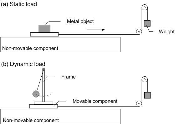
Schematic diagram of the setup for experimental verification using (a) a 24-kg stationary object and (b) an 8.4-kg pendulum, both placed on the movable component which was pulled horizontally by a 1.0-kg weight and glided along the non-movable component with a friction coefficient less than 0.04.
In the last set of verification, we inspected a set of existing data of young adults who slipped unexpectedly while walking in our protective laboratory environment (Bhatt et al., 2006). During the experiment, they were instructed to walk at their preferred regular speed, and they “may or may not be slipped”. After 10 trials in which the starting position was adjusted to ensure a complete landing of the right foot onto the movable plate, this plate was released for the first time, unaware to the subjects, at touchdown to induce a slip. The kinematic tracking and the kinetic GRF data were used to derive resultant joint moments (Pai et al., 2006) and calculate corrected and uncorrected Fx1, Fz1, and xCOP based on Eqs (3-7).
RESULTS
Our sensitivity analyses revealed that for a given movable component and Fz1, the COP offset increased proportionately with μ and ax (Fig. 3). The magnitude of the COP offset (|(u−v)|) decreased proportionately when landing position was closer to the COM (i.e., |u| reduced Fig. 3). When Fz1 was 700 N and all other parameters changed within their respective ranges as stated above, this proportionality for ax, μ, and u was 6.04 × 10⁻⁵ [m/(m/s2)], 0.058 [m], and −0.036 [m/m], respectively. At a given condition (e.g., ax = 5 m/s2, μ = 0.02, u = −0.15m, and Fz1 = 700N), the coefficients of sensitivity for m, σ, H, and Fz1 were 0.002 [m/kg], 0.001 [m], 0.025 [m/m] and −7.94 × 10⁻⁶ [m/N], respectively. Within the acceleration range we have investigated, the magnitude of the COP offset increased with the increases of m and H (Fig. 3-a, b). When σ increased, the COP offset increased when ax is positive, but decreased when ax was negative (Fig. 3-c). With a reduction in Fz1, the COP offset increased (Fig. 3-e).
Fig. 3.

Sensitivity analyses of the COP offset as a function of the acceleration (ax = −10 to 20 m/s2), the coefficient of friction (μ = 0.02: the left column and 0.04: the right column). Other parameters evaluated include (a) mass (m = 2.5, 5.0, and 7.5 kg), (b) the vertical dimension (H = 0.05, 0.10, and 0.15 m), (c) COM position (σ = 0.25, 0.5, and 0.75), (d) landing position (u = −0.15, 0, and 0.15 m), and (e) the vertical force (Fz1 = 500, 700, and 900 N). The offset is positive when the uncorrected COP of Fz2 is anterior to the corrected COP of Fz1; and u is positive when the foot lands anterior to the COM. Where not specified, m = 2.5 kg, H = 0.05 m, σ = 0.25, u = −0.15 m, and Fz1 = 700 N.
The verifications using a stationary object and using a pendulum both revealed that the corrected COP trajectory derived from Eq (11) was very close to the “actual” trajectory derived from equations of motion for the stationary object and the pendulum (Fig. 4). The closeness of the fit of the COP trajectories was estimated by their correlation coefficient (R2). The root mean square (RMS) of the residual error between the COP trajectories was adopted to indicate the magnitude of the error. The mean (± 1SD) of R2 of the “actual” and corrected COP trajectories and of the “actual” and uncorrected COP trajectories were 0.996 ± 0.001 and 0.995 ± 0.001 for the stationary objects, and 0.997 ± 0.001 and 0.994 ± 0.001 for the pendulum across 8 trials. The corresponding mean RMS (± 1SD) for these trials were 2.7 ± 0.9 mm and 28.6 ± 4.6 mm for the stationary objects, and 3.8 ± 0.5 mm and 16.7 ± 3.8 mm for the pendulum.
Fig. 4.

The corrected (dash) and uncorrected (dash-dot) COP trajectories derived directly from force platform measurements for (a) a stationary object and (b) a pendulum were compared with ““actual”” trajectory derived primarily from motion capture data (solid). The correlation coefficients of the “actual” and corrected COP (solid and dash lines) and of the “actual” and uncorrected COP (solid and dot lines) respectively are 0.998 and 0.998 for the stationary object, and 0.997 and 0.995 for the pendulum. The corresponding root mean squares are 2.1 mm and 29.5 mm for the stationary object, and 2.4 mm and 15.2 mm for the pendulum. A portion of the curves was enlarged to illustrate more clearly the consistency.
Verification carried out with human subjects stepping on this low friction platform demonstrated the magnitude of the correction required in such experimental settings. In one example, a subject experienced backward balance loss, and had to take one protective step on the contralateral side before the slipping limb liftoff from the movable platform (Fig. 5). The maximum error in the COP, when uncorrected, reaches as much as 4 cm (Fig. 5-a), which was more than 15% of this person's foot length. For the horizontal force, the peak error was close to 45 N, about 9% of a person's body weight (Fig. 5-b). The combined errors from the GRF and its COP substantially affect the subsequent calculation of resultant joint moments (Fig. 5-c, e, and g) and reaction forces (Fig. 5-d, f, and h). The error introduced by the inertial effect of the movable component into the joint moment calculations appears to be magnified as the calculation proceeds proximally, ranging from 0.2 Nm/body mass at the ankle to 1.0 Nm/body mass at the hip. Also, the inertial effect was most prominent during the early phase of the perturbation, before the liftoff of the contra-lateral (trailing) foot (Fig. 5-c∼h).
Fig. 5.

In an example showing inertia-related error, a subject (body mass = 50.0 kg) slipped forward and experienced a backward balance loss during the stance phase in gait after her right (slipping) limb landed on the movable component of a device. The time-history results from the right limb shown here include (a) the center of pressure (COP, solid line) and COP offset (dash line) as well as a comparison between the uncorrected (dash) and the corrected (solid) (b) horizontal component of the ground reaction force (GRF), (c, e, and g) resultant joint moments, and (d, f, and h) resultant joint forces at ankle; knee and hip, respectively. Time is normalized as a percentage of the total duration of the stance phase (0.81-s) from its touchdown, t0, to liftoff, tf, from the movable component. Two thin vertical lines mark the timing of the liftoff (solid) and touchdown (dash) during the recovery with the contralateral limb, which landed outside of the moving component without affecting the results of the right limb shown here. The COP is relative to its value at t0. The GRF and the resultant joint forces are normalized by body weight, and the resultant joint moments by the body mass, where positive represents extension (plantar flexion) moments.
DISCUSSION
Our analyses reveal that the amount of COP correction required due to the inertial effect of the movable component is a function of its physical properties (m, H, and σ) and forces (μ and Fz1), acceleration (ax), and the foot landing position (u). For a given movable component, greater acceleration require greater correction of inertial effect. The required correction increases when landing position is further away from the COM. Because u, ax, Fx2 / Fx2, and Fz1 vary during a trial and from trial to trial, the inertial effect of the movable component can only be eliminated by the method outlined in the present study, rather than by a re-calibration method.
The discrepancy between the corrected COP trajectory and the “actual” trajectory (Fig. 4) may be attributable to various factors, such as the noise in the acquired signals, error in the dimensional measurement, or errors in the estimated slider inertial properties (Preuss and Fung, 2004). Some small errors may also result from imprecision in the acquired force platform signals (such as cross–talk between channels due to errors in strain gauge orientation) or from minor signal distortions occurring in the digitization process due to sampling limitations. Taken together, this discrepancy may be indicative of the inherent limitations associated with both measurement systems.
Previous studies have shown similar results. For instance, Robinson and associates (1998) found that the shear force and acceleration of the movable component both influence the COP offset when the force platform upon which the person stood was moved by a motorized device. These results were similar to those provided here, because the increase in the friction coefficient in the present study was associated with a proportional increase in the shear force. Nevertheless, because the feet position on the force platform was fixed in their study, the influence of the relative landing position on the COP shift had not been considered (Robinson et al., 1998).
Moreover, we found that the inertial effect of the movable platform on the joint moment computations is magnified as the calculations proceed from distal joints to proximal ones. This finding was consistent with conclusions drawn previously (Preuss and Fung, 2004). During balance recovery following a slip, the error due to the inertial effect reached as much as 40N in the anterior/posterior component of the GRF among our 24 subjects. This is substantially smaller than the previously reported correction of 140 N (Preuss and Fung, 2004). The differences between the two studies in the corrections made for resultant joint moments were also substantial (Preuss and Fung, 2004). It is likely that these discrepancies can be explained by the difference in the mass of the movable components; theirs consisted of a 15 kg force platform, ours was a mere 2.7 kg. The smaller mass of the movable component should have less inertial impact on the GRF and joint moment calculations.
Finally, most of the inertia-related error in the COP and the joint moments occurs during the early part of the balance recovery when the acceleration of the gliding foot reaches its maximum. This is an important period in deciding the outcomes of the subsequent recoveries. It has been noted that 96% of backward balance loss can be correctly predicted by gait stability at liftoff of the trailing limb, approximately 100 ms following the slip onset (Bhatt et al., 2006). It has also been revealed that during a period of within 300 ms following a slip induced at seat-off in sit-to-stand, the insufficient concentric extension work produced at knee and hip joints can lead to subsequent failure in recovery and limb collapse (Pai et al., 2006). The corrections of instrumentation related errors across these periods can, therefore, be non-trivial, even if the mass of the movable component is relative small (Fig. 5).
In summary, the present study has established a computational method crucial for removing inertial effect when using a non-motorized platform to induce long-distance slips during walking. Without such a correction for the inertial effect, acceleration, forces, and physical properties of the movable component and the relative landing position of the foot all can introduce error in the GRF and COP measurements; quite significantly, this error becomes magnified in the computation of the joint resultants.
Supplementary Material
Acknowledgements
This work was funded by NIH 2R01-AG16727. The authors thank Debbie Espy for editing, and the reviewers for their constructive comments.
Footnotes
Publisher's Disclaimer: This is a PDF file of an unedited manuscript that has been accepted for publication. As a service to our customers we are providing this early version of the manuscript. The manuscript will undergo copyediting, typesetting, and review of the resulting proof before it is published in its final citable form. Please note that during the production process errors may be discovered which could affect the content, and all legal disclaimers that apply to the journal pertain.
References
- Bhatt T, Wening JD, Pai Y-C. Adaptive control of gait stability in reducing slip-related backward loss of balance. Experimental Brain Research. 2006;170:61–73. doi: 10.1007/s00221-005-0189-5. [DOI] [PubMed] [Google Scholar]
- Bhatt T, Wening JD, Pai Y-C. Influence of gait speed on stability: recovery from anterior slips and compensatory stepping. Gait and Posture. 2005;21:146–156. doi: 10.1016/j.gaitpost.2004.01.008. [DOI] [PubMed] [Google Scholar]
- Brady RA, Pavol MJ, Owings TM, Grabiner MD. Foot displacement but not velocity predicts the outcome of a slip induced in young subjects while walking. Journal of Biomechanics. 2000;33:803–808. doi: 10.1016/s0021-9290(00)00037-3. [DOI] [PubMed] [Google Scholar]
- Ferber R, Osternig LR, Woollacott MH, Wasielewski NJ, Lee J-H. Reactive balance adjustments to unexpected perturbations during human walking. Gait and Posture. 2002;16:238–248. doi: 10.1016/s0966-6362(02)00010-3. [DOI] [PubMed] [Google Scholar]
- Henry SM, Fung J, Horak FB. Control of stance during lateral and anterior/posterior surface translations. IEEE Transactions on Rehabilitation Engineering. 1998;6:32–42. doi: 10.1109/86.662618. [DOI] [PubMed] [Google Scholar]
- Horak FB. Adaptation of automatic postural responses. In: Bloedel JR, Ebner J, Wise SP, editors. The Acquisition of Motor Behavior in Vertebrates. The MIT Press; Cambridge, MA.: 1996. pp. 57–85. [Google Scholar]
- Horak FB, Henry SM, Shumway-Cook A. Postural perturbations: new insights for treatment of balance disorders. Physical Therapy. 1997;77:517–533. doi: 10.1093/ptj/77.5.517. [DOI] [PubMed] [Google Scholar]
- Horak FB, Nashner LM. Central programming of postural movements: adaptation to altered support-surface configurations. Journal of Neurophysiology. 1986;55:1369–1381. doi: 10.1152/jn.1986.55.6.1369. [DOI] [PubMed] [Google Scholar]
- Macpherson JM, Horak FB, Dunbar DC, Dow RS. Stance dependence of automatic postural adjustments in human. Experimental Brain Research. 1989;78:557–566. doi: 10.1007/BF00230243. [DOI] [PubMed] [Google Scholar]
- Maki BE. Is center of mass a controlled parameter? In Satellite to the Annual Meeting of the Society for Neuroscience; Los Angeles. 1998. [Google Scholar]
- McIlroy WE, Maki BE. Adaptive changes to compensatory stepping responses. Gait and Posture. 1995;3:43–50. [Google Scholar]
- Muller ML, Redfern MS. Correlation between EMG and COP onset latency in response to a horizontal platform translation. Journal of Biomechanics. 2004;37:1573–1581. doi: 10.1016/j.jbiomech.2004.01.004. [DOI] [PubMed] [Google Scholar]
- Nashner L. Adapting reflexes controlling the human posture. Experimental Brain Research. 1976;26:59–72. doi: 10.1007/BF00235249. [DOI] [PubMed] [Google Scholar]
- Nashner LM. Balance adjustments of humans perturbed while walking. Journal of Neurophysiology. 1980;44:650–664. doi: 10.1152/jn.1980.44.4.650. [DOI] [PubMed] [Google Scholar]
- Pagnacco G, Silva A, Oggero R, Berme N. Inertially compensated force plate: a means for quantifying subject's ground reaction forces in non-linear conditions. Biomedical Sciences Instrumentation. 2000;36:397–402. [PubMed] [Google Scholar]
- Pai Y-C. Induced limb collapse in a sudden slip during termination of sit-to-stand. Journal of Biomechanics. 1999;32:1377–1382. doi: 10.1016/s0021-9290(99)00126-8. [DOI] [PubMed] [Google Scholar]
- Pai Y-C, Yang F, Wening JD, Pavol MJ. Mechanisms of limb collapse following a slip among young and older adults. Journal of Biomechanics. 2006;39:2194–2204. doi: 10.1016/j.jbiomech.2005.07.004. [DOI] [PubMed] [Google Scholar]
- Pavol MJ, Owings TM, Grabiner MD. Body segment inertial parameter estimation for the general population of older adults. Journal of Biomechanics. 2002;35:707–712. doi: 10.1016/s0021-9290(01)00250-0. [DOI] [PubMed] [Google Scholar]
- Preuss R, Fung J. A simple method to estimate force plate inertial components in a moving surface. Journal of Biomechanics. 2004;37:1177–1180. doi: 10.1016/j.jbiomech.2003.12.007. [DOI] [PubMed] [Google Scholar]
- Robinson CJ, Purucker MC, Faulkner LW. Design, control, and characterization of a sliding linear investigative platform for analyzing lower limb stability (SLIP-FALLS) IEEE Transactions on Rehabilitation Engineering. 1998;6:334–350. doi: 10.1109/86.712232. [DOI] [PubMed] [Google Scholar]
- Tang PF, Moore S, Woollacott MH. Correlation between two clinical balance measures in older adults: functional mobility and sensory organization test. Journals of Gerontology. Series A, Biological Sciences and Medical Sciences. 1998;53:M140–146. doi: 10.1093/gerona/53a.2.m140. [DOI] [PubMed] [Google Scholar]
Associated Data
This section collects any data citations, data availability statements, or supplementary materials included in this article.