

Abstract
The objective of this research was to study the reinforcement of electrospun nylon 6/fibrillar silicate nanocomposite nanofibers on Bis-GMA/TEGDMA dental composites. The hypothesis was that the uniform distribution of nano-scaled and highly aligned fibrillar silicate single crystals into electrospun nylon 6 nanofibers would improve the mechanical properties of the resulting nanocomposite nanofibers, and would lead to the effective reinforcement of dental composites. The nylon 6/fibrillar silicate nanocomposite nanofibers were crystalline, structurally oriented and had an average diameter of approximately 250 nm. To relatively well distribute nanofibers in dental composites, the nanofiber containing composite powders with a particle structure similar to that in interpenetration networks were prepared first, and then used to make the dental composites. The results indicated that small mass fractions (1 % and 2 %) of nanofiber impregnation improved the mechanical properties substantially, while larger mass factions (4 % and 8 %) of nanofiber impregnation resulted in less desired mechanical properties.
Keywords: Electrospinning, Nanofiber, Dental Composite
INTRODUCTION
Developed over 40 years ago, dental composites have been widely adopted by the profession to replace traditional “dental amalgams”, alleviating both safety and esthetic concerns. Dental composites are usually cured (hardened) by photo-initiated free radical polymerization (photopolymerization). Camphorquinone (CQ) is a commonly used visible-light initiator and ethyl-4-(N,N’-dimethylamino) benzoate (4EDMAB) is a commonly used co-initiator. The monomer 2,2’-bis-[4-(methacryloxypropoxy)-phenyl]-propane (Bis-GMA) has been widely used as an important dental base monomer since it was invented in early 1960’s [1,2]. Bis-GMA is a very viscous, honey-like liquid. To improve the handling qualities, a low viscosity diluent monomer, such as tri (ethylene glycol) dimethacrylate (TEGDMA), is added to thin the resin. In Bis-GMA/TEGDMA dental resin systems, Bis-GMA functions to limit the photopolymerization induced volumetric shrinkage and to enhances resin reactivity, while TEGDMA provides for increased vinyl double bond conversion [3,4]. Conventionally, Bis-GMA/TEGDMA dental resins are reinforced with inorganic fillers, and the mass faction of inorganic fillers in commercial dental composites is as high as 75 %. While there are numerous types of inorganic fillers, most consist of ceramic (such as silica/glass) particles. The relatively low strength and durability of the composites, however, have limited their uses [5-8]. The strength of the inorganic filler reinforced dental composites is usually in the range from 80 to 120 MPa, and the average lifetime is 5 years or less. By comparison, dental amalgams have strength over 400 MPa and have a lifetime of more than 15 years [9,10]. Investigations of the reasons for failure revealed that, among other things, inorganic filler was a major contributor [5-8]. Ironically, the inorganic fillers which are added for the purpose of fortifying the dental composites are actually responsible, at least in part, for the demise. Stresses are transmitted onto the filler particles projecting from the occlusal surfaces through the boluses of foods during chewing. Since the inorganic filler particles are considerably harder than the dental resin matrices, the stresses are transmitted through the filler to the resin. Wherever the submerged portions of the filler particles are angulated or irregular in shape, the stress concentration may become excessively high.Such a condition tends to generate small cracks around the filler particles, thereby weakening the matrices locally.
Reinforcement with electrospun nanofibers has been shown to result in substantial improvements on mechanical properties of dental composites. Our previous research revealed that the impregnation of 5 % (mass fraction) neat nylon 6 nanofibers into Bis-GMA/TEGDMA (50/50 mass ratio) dental resin improved the flexural strength by 36 %, the elastic modulus by 26 %, and the work-of-fracture by 42 % [11]. Nylon 6 nanofibers are much more ductile than inorganic fillers, and have a regular cylindrical shape. During electrospinning [12-15], the key phenomenon known as “bending instability” elongates the electrospinning jet up to 100,000 times in less than one tenth of a second [16]. This results an extremely large draw ratio which can closely align macromolecular chains along the nanofiber axis and make electrospun nanofibers mechanically strong. The small diameter of nanofibers also provides for a large ratio of surface area to volume, which can enhance the intermolecular hydrogen bonding between the nylon 6 nanofiber filler and the Bis-GMA/TEGDMA resin matrix. Furthermore, electrospun nanofibers are continuous. If a micro-crack is initiated in a matrix under contact wear and/or other stresses, the nanofibers remain intact across the crack planes and support the applied load. Therefore, crack-opening is resisted by the nanofibers, and the matrix is reinforced.
In our previous study, electrospun nylon 6 nanofibers (collected in the form of felt/mat) were impregnated into the Bis-GMA/TEGDMA dental resin layer by layer [11]; such a fabrication method is apparently not applicable for making dental pastes [8]. Furthermore, the modulus and strength of the neat nylon 6 nanofibers may not be high enough to effectively reinforce photo-cured dental resin matrices, which are heavily cross-linked three dimensional networks. In this study, investigations were carried out to evaluate the reinforcement of electrospun nylon 6/fibrillar silicate nanocomposite nanofibers. The uniform distribution of nano-scaled and surface silanized fibrillar silicate single crystals into nylon 6 nanofibers, with the single crystals highly aligned along the nanofiber axes, improved the strength and modulus of the resulting nanocomposite nanofiber. The silanized single crystals on the surface of nanofibers also enhance the intermolecular interaction/bonding between the nanofiber filler and the resin matrix. Thus, the nylon 6/fibrillar silicate nanocomposite nanofibers are expected to significantly outperform the neat nylon 6 nanofibers on reinforcement of dental composites. During this research, instead of being impregnated layer by layer, the felt/mat of electrospun nylon 6/fibrillar silicate nanocomposite nanofibers was soaked with dental monomers first. After the soaked felt was photo-cured, the resulted composite (in the form of thin plate) was then milled into a powder with an average particle size of approximately 20 μm. Subsequently, the powder was mixed with dental monomers to prepare dental pastes containing nanofibers of various mass fractions (1 %, 2 %, 4 % and 8 %). Finally, the pastes were photo-cured, and the fabricated composites were characterized/evaluated. The powders without nanofiber and with neat nylon 6 nanofibers were also prepared and used to fabricate dental composites for comparison as control samples.
Fibrillar silicate is a class of hydrated magnesium/aluminum silicate. There are several types of fibrillar silicate minerals found in nature. The most abundant type is known as attapulgite/palygorskite, which is widely found in the United States and China. The fibrillar silicate used in this study was attapulgite, and its chemical formula is Mg5[Al]Si8O20(HO)2(OH2)4·4H2O. The primary structural units of fibrillar silicate are silicate single crystals that are 100-3000 nm in length and 10-25 nm in diameter. These single crystals stack/agglomerate into particles with sizes in microns (see Fig. 1). The fibrillar silicate single crystals possess a high degree of structural perfection and the concomitant superior mechanical properties. The strength and modulus of the single crystals are over 50 GPa and 500 GPa, respectively [17]; which are at least 5 times higher than those of conventional fibers. Unlike layered silicates such as montmorillonite, fibrillar silicate is much easier to separate into nano-scaled single crystals and to uniformly distribute in polymer matrices. This is because the spacing among the aggregated single crystals in fibrillar silicate is much larger than that of the silicate layers in montmorillonite. As a result, the interaction (van der Waals force) of the single crystals in fibrillar silicate is considerably weaker than that of the silicate layers in montmorillonite. Fibrillar silicate can readily achieve the uniform distribution in polymer matrices by a simple extrusion process [18,19], even without chemical substitution of metal ions with surfactants such as tertiary amines (a widely adopted method for intercalation/exfoliation of layered silicates to prepare nanocomposites.) Additionally, there are abundant Si–OH groups on the surface of fibrillar silicate single crystals, and these groups can react with silane coupling agents such as (3-glycidyloxypropyl) trimethoxysilane (GOPTMS) [19]. The interfacial bonding between the silanized fibrillar silicate single crystal filler and the nylon 6 matrix can be reasonably strong.
Figure 1.
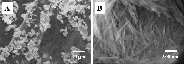
Representative SEM images of the as-received fibrillar silicate powder: (A) low magnification, and (B) high magnification.
EXPERIMENTAL
Materials
Nylon 6 pellets (product number: 2230, weight-average molecular weight Mw ~ 10,000 g/mol) were purchased from DSM Co. (Heerlen, Netherlands). Purified fibrillar silicate powder (1250 mesh, white/gray in color) was purchased from Dalian Global Mineral Co. (Dalian, China). Bis-GMA and TEGDMA were provided by Esstech Co. (Essington, PA). CQ, 4EDMAB, GOPTMS, n-propylamine, anhydrous ethanol and 1,1,1,3,3,3-hexafluoro-2-propanol (HFP) were purchased from Sigma-Aldrich Co. (Milwaukee, USA). All of the materials were used without further purification.
Sample Preparation
Silanization of Fibrillar Silicate
The as-received fibrillar silicate powder was first dispersed in anhydrous ethanol with a mass fraction of 5 %, and the suspension was then vigorously stirred for 4 h at 400 rpm using a Heidolph RZR 50 Heavy Duty Stirrer. Previous research indicated that this process could effectively separate fibrillar silicate particles/agglomerates into nano-scaled single crystals [18,19]. Subsequently, the suspension was transferred into a rotary evaporator with GOPTMS (mass fraction of 10 % to fibrillar silicate) and n-propylamine (mass fraction of 5 % to fibrillar silicate). The system was then heated at 90 ° C until dry to prepare the silanized fibrillar silicate.
Preparation of Nylon 6/Fibrillar Silicate Nanocomposite
The as-received nylon 6 pellets were first dried in a desiccant air dryer at 90 ° C for 24 h. The dried nylon 6 was then blended with the silanized fibrillar silicate (mass fraction of 7 % to nylon 6) using a ZSK-25 twin screw extruder made by the WP Company. The extruder had a screw diameter of 35 mm and a length/diameter (L/D) ratio of 45. During operation, the screw speed was set at 300 rpm, and the temperatures of the individual sections/barrels of the extruder were set at 230, 235, 240, 245, 240, and 235° C, respectively. The extruded nylon 6/fibrillar silicate nanocomposite pellets were used to make electrospun nanofibers. Extruded neat nylon 6 pellets were also prepared using the same processing conditions for comparison purposes.
Electrospinning and Nanofiber Preparation
Solutions of 8 % (mass fraction) nylon 6 (or nylon 6/fibrillar silicate nanocomposite) in HFP were prepared at room temperature, and a specially designed spinneret was used for conducting electrospinning. The spinneret consisted of a high-density polypropylene tube with an inner diameter of 1.0 inch and a stainless steel hemispherical head with an orifice of 0.4 mm diameter at the center. The electrospinning setup included a high voltage power supply (model number: ES30P), purchased from Gamma High Voltage Research, Inc. (Ormond Beach, USA), and a home-built roller with a diameter of 10 inches. During electrospinning, a positive high voltage of 25 kV was applied through a thin stainless steel rod to the solution held inside the spinneret. Nylon 6 (or nylon 6/fibrillar silicate nanocomposite) nanofibers were collected on the electrically grounded aluminum foil that covered the roller. The rotational speed of the roller during electrospinning was set at 100 rpm. This process of electrospinning was extremely stable, and the electrospinning jet ran continuously without breaking for several hours. The felt/mat collected on the aluminum foil was, hypothetically, a single nanofiber loosely aligned along the rolling direction. A heating lamp was used to dry the nanofiber felt during electrospinning, and the felt was further dried after electrospinning in a vacuum oven at 80° C for 12 h. The collected nanofiber felt had a thickness around 100 μm and a mass per unit area of approximately 60 g/m2.
Preparation of Dental Composites
The (nylon 6 or nylon 6/fibrillar silicate nanocomposite) nanofiber felt was first cut into pieces of about 5 cm in length and width. The felt pieces were then soaked in the dental resin mixture, which consisted of 49.5 % Bis-GMA, 49.5 % TEGDMA (making a 50/50 mass ratio of Bis-GMA/TEGDMA), 0.2 % CQ and 0.8 % 4EDMAB. When no air bubbles could be seen, the soaked felt pieces (now approximately 5 times thicker than before) were carefully taken out of the dental resin mixture, put on a glass plate, and then transferred into a “TRIAD 2000” chamber (Dentsply International, Inc., USA) to be photo-cured for 2 min. The obtained composites had a nanofiber content of 20 % (mass fraction), and the nanofibers were uniformly distributed in the composites. The composites were then milled into powders with an average particle size of approximately 20 μm. Finally, the powders were mixed with the dental resin mixture (composition as described above) to prepare dental pastes containing nanofibers of various mass fractions (1 %, 2 %, 4 % and 8 %). The powder without nanofiber was also prepared to make the dental pastes for comparison as control samples. To prepare the three-point flexural testing specimens, the dental pastes were photo-cured for 2 min in a homemade Teflon mold using three standard visible light curing units (Maxima 480) purchased from L. D. Caulk Co. (Milford, DE). Since the dimension of specimens was 2 mm x 2 mm x 25 mm, tips of the three light curing units were put together in a row to allow effective photo-curing. Prior to mechanical testing, the photo-cured specimens were stored in a humidifier at 37 °C for 24 h. Six specimens were prepared for each measurement, and all four sides of the specimens were carefully hand-polished with 2400 and 4000 grit silicon carbide paper and water coolant in a longitudinal direction. The preparations of dental composites were conducted in a yellow-light room to avoid the premature curing.
Characterization and Evaluation
Morphologies and Structures
A Zeiss Supra 40VP field-emission scanning electron microscope (SEM), a Hitachi H-7000 FA transmission electron microscope (TEM), and a Rigaku Ultima Plus X-Ray diffractometer (XRD) were employed to examine the morphologies and structures of fibrillar silicate, nylon 6/fibrillar silicate nanocomposite, electrospun nylon 6 and nylon 6/fibrillar silicate nanocomposite nanofibers, and the representative fracture surfaces of the prepared Bis-GMA/TEGDMA dental composites. Prior to SEM examination, the specimens were sputter-coated with gold to avoid charge accumulation. For TEM examination of nylon 6/fibrillar silicate nanocomposite, the specimen was microtomed at room temperature using a Reichert-Jung Ultracut Microtome and mounted on 200 mesh copper grids. For XRD experiments, a rotating X-ray generator (40 kW, 40 mA) with CuKα radiation (wavelength λ = 1.54Å) was used. The XRD profiles were recorded from 3 to 35° at the scanning speed of 2° min-1. The XRD specimens were the collected nanofiber felt.
Mechanical Properties
A standard three-point flexural test (ASTM D 793) with a span of 20 mm was used to fracture the specimens at a crosshead speed of 0.5 mm/min using a computer-controlled universal mechanical testing machine (QTESTTM/10, MTS Systems Co., USA). Flexural strength (SF), elastic modulus (EY), and work-of-fracture (WOF) were calculated using the following formulas:
Where P is the load at fracture, L is the distance between two supports (which was set to be 20 mm), W is the width of the specimen, T is the thickness of the specimen, d is the deflection at load P, and A is the area under the load-displacement curve (which is the work done by the applied load to deflect and fracture the specimen.)
RESULTS AND DISCUSSION
Nylon 6/Fibrillar Silicate Nanocomposite
Naturally occurring fibrillar silicate minerals usually contain some impurities including silica and carbonates. These impurities have been removed in the as-received fibrillar silicate powder. Fig. 1A and B are, respectively, the low and high magnification SEM images of the as-received powder. It was evident that the powder was composed of fibrillar silicate agglomerates/particles ranged from submicron to several microns in size, and the agglomerates/particles consisted of nano-scaled single crystals with diameters in tens of nanometers and lengths in microns.
The as-received fibrillar silicate powder was silanized using the procedure as described in the experimental section. Fig. 2A is a TEM image showing the (silanized and separated) single crystals. To prepare the TEM specimen, the silanized fibrillar silicate was first dispersed in ethanol with a mass fraction of 1 %, and the suspension was then vigorously stirred for 30 min at 400 rpm using the Heidolph RZR 50 Heavy Duty Stirrer. Subsequently, the carbon-coated TEM grid was dipped into the suspension, which had no clearly identifiable solid/precipitate, and quickly removed. After the ethanol in the leftover suspension on the TEM grid evaporated, the specimen was used for TEM examination. It is noted that, although the silanized fibrillar silicate was well distributed as nano-scaled single crystals in Fig. 2A (presumably due to the fast evaporation rate of ethanol in the method to prepare the TEM specimen), there may have been agglomerates/particles in the silanized fibrillar silicate powder.
Figure 2.
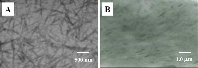
TEM images of (A) separated and silanized fibrillar silicate single crystals, and (B) nylon 6/fibrillar silicate nanocomposite.
The silanized fibrillar silicate powder was then blended/extruded with the pre-dried nylon 6 pellets to prepare the nylon 6/fibrillar silicate nanocomposite. To study the fibrillar silicate distribution in nylon 6 by TEM, the nanocomposite was microtomed into specimens with thicknesses less than 100 nm. As shown in Fig. 2B, the silanized fibrillar silicate single crystals were uniformly distributed in nylon 6, and no agglomerate/particle was identified by the microscope. This indicated that the adopted silanization and extrusion procedures/conditions resulted in the formation of nylon 6/fibrillar silicate nanocomposite. When compared to those in Fig. 2A, the single crystals in Fig 2B seemed shorter. This suggested that the extensive shearing associated with the twin-screw extrusion process broke some of the single crystals. In spite of the breakage, the aspect ratios of most single crystals in the prepared nanocomposite were larger than 10, so that the effective reinforcement should still be able to achieve [20].
Electrospun Nanofibers
The electrospun nanofibers of neat nylon 6 and nylon 6/fibrillar silicate nanocomposite had diameters in the range from 100 to 400 nm, while the average diameter was about 250 nm. Fig. 3A and B are the SEM images showing the representative morphologies of the prepared neat nylon 6 and nylon 6/fibrillar silicate nanocomposite nanofibers, respectively. During the SEM examination, there were no beads and/or beaded nanofibers [21] identified, primarily due to the specially designed electrospinning setup. As described in the experimental section, the electrospinning process using this setup was extremely stable, and the electrospinning jet ran continuously without breaking for hours. This led to the formation of relatively uniform nanofibers without beads and/or beaded nanofibers. It is noted that the nanofibers as shown in Fig. 3 were purposely collected for the SEM examination; the actual nanofiber felt used for the fabrication of dental composites was much denser. When examination of the nanofibers with a polarized optical microscope (POM), birefringence was observed, suggesting nylon 6 macromolecules/crystallites were oriented in nanofibers. Nanofibers with diameters less than 150 nm enabled direct imaging with TEM to acquire the detailed interior morphology. As shown in Fig. 4, the fibrillar silicate single crystals (dark lines in nanofibers) were well distributed and closely aligned along the nanocomposite nanofiber axes.
Figure 3.
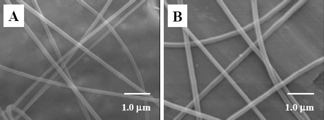
Representative SEM images of (A) neat nylon 6 nanofibers, and (B) nylon 6/fibrillar silicate nanocomposite nanofibers.
Figure 4.
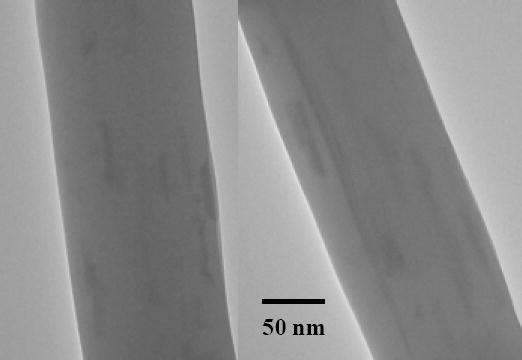
TEM images showing two segments of nylon 6/fibrillar silicate nanocomposite nanofibers containing 7 % (mass fraction) silanized fibrillar silicate single crystals.
XRD characterization was conducted to determine the crystalline morphology of nylon 6 and nylon 6/fibrillar silicate nanocomposite nanofibers. As shown in Fig. 5, both types of nanofibers showed strong diffraction peak at the 2θ angle of approximately 21º (d-spacing = 0.423 nm), characteristic of the γ-crystalline structure of nylon 6 [22]. Such XRD profiles indicated that, similar to conventional spinning methods such as melt spinning, electrospinning also resulted in the formation of γ crystalline structure of nylon 6. Since the formation of γ crystalline structure of nylon 6 typically requires extensive drawing/stretching [22], the nylon 6 macromolecular chains in the electrospun nanofibers were believed to be drawn/stretched and the nanofibers would be mechanically strong. As compared to that of the neat nylon 6 nanofibers (curve “1” in Fig. 5), the XRD diffraction peak (at the 2θ angle of approximately 21º) of the nylon 6/fibrillar silicate nanocomposite nanofibers (curve “2” in Fig. 5) was broader (the width of the diffraction peak measured at half its height was larger). This suggested that the average size of nylon 6 crystallites in the nanocomposite nanofibers was smaller than that in neat nylon 6 nanofibers [23]. This result was consistent with the TEM examination, since the uniform distribution of nano-sized fibrillar silicate single crystals could confine the growth of nylon 6 crystallites in nanofibers. The XRD profile of the nanocomposite nanofibers also showed two other diffraction peaks at the 2θ angles of 8.3º (d-spacing = 1.065 nm) and 26.5º (d-spacing = 0.336 nm), which were originated from fibrillar silicate single crystals [18]. Small Angle X-ray Scattering (SAXS) could also have been employed to investigate long range ordering of the distributed fibrillar silicate single crystals in the nanofibers. The investigation was not actually conducted because TEM results already suggested that the single crystals were quite uniformly distributed in the nanocomposite nanofibers, and the separation distance (spacing) among the single crystals was tens of nanometers. No matter the long range ordering exited or not, it should not significantly affect the mechanical properties of nanofibers, which was the main concern in this research.
Figure 5.
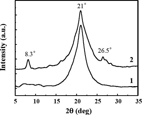
XRD profiles of (1) neat nylon 6 nanofibers, and (2) nylon 6/fibrillar silicate nanocomposite nanofibers. The profiles are offset for clarity.
Dental Composites
After the (nylon 6 or nylon 6/fibrillar silicate nanocomposite) nanofiber felt was soaked with CQ/4EDMAB activated Bis-GMA/TEGDMA (50/50 mass ratio) dental monomers, the felt became approximately five times thicker. After photopolymerization, the structure of the resulting composites (in the form of thin plate) was similar to that of interpenetration networks, except that the interpenetration occurred at nano-scale instead of at molecular-scale. The composites were then milled into powders with the average particle size of approximately 20 μm. Subsequently, the powders were mixed with CQ/4EDMAB activated Bis-GMA/TEGDMA (50/50 mass ratio) dental monomers to make dental pastes containing nanofibers in various mass fractions (1 %, 2 %, 4 % and 8 %). Finally, the pastes were photo-cured, the dental composite specimens were mechanically tested, and the representative fracture surfaces (of the three-point flexural testing specimens) were examined by SEM. The powder without nanofiber was also prepared and used to fabricate dental composites for comparison as control samples. It is noted that the prepared powders were actually composites with the matrix being photo-cured Bis-GMA/TEGDMA (50/50 mass ratio) dental resin; and the vinyl double bond conversion of the resin was approximately 80 % [4]. The powders in the dental paste could be swollen by Bis-GMA/TEGDMA monomer molecules. Since these monomer molecules would eventually be photo-cured, any existing interfaces between the powder (particles) and matrices in the final dental composites should be very good.
The mechanical properties of the dental composites containing 1 %, 2 %, 4 % and 8 % (mass fractions) of electrospun nylon 6 nanofibers (gray bars) or nylon 6/fibrillar silicate nanocomposite nanofibers (black bars), as well as the mechanical properties of the control samples (white bars), were measured and the results are shown in Fig. 6. The same mass fractions of the powders (with or without nanofibers) were maintained for each of the sample group (consisting of one white bar, one gray bar and one black bar). Each bar in the plots represents the mean value of six measurements, with the error bar showing one standard deviation. Fig. 6 indicated that the flexural strength (SF), elastic modulus (EY) and work of fracture (WOF) of the resulting composites were all substantially increased by impregnation of small mass fractions of nanofibers in the Bis-GMA/TEGDMA dental resin. For the 2.0 % (mass fraction) neat nylon 6 nanofiber reinforced composite, the SF, EY and WOF values (mean ± standard deviation, n =6) were (106 ± 6) MPa, (2.4 ± 0.1) GPa and (6.7 ± 0.5) kJ/m2, respectively. For the 2.0 % (mass fraction) nylon 6/fibrillar silicate nanocomposite nanofiber reinforced composite, the SF, EY and WOF values were (117 ± 5) MPa, (2.5 ± 0.1) GPa and (8.5 ± 0.5) kJ/m2, respectively. The SF, EY and WOF values of the control sample were (95 ± 5) MPa, (2.0 ± 0.2) GPa and (4.3 ± 0.5) kJ/m2, respectively. This indicates that the SF was improved by 23 %, the EY was improved by 25 %, and the WOF was improved by 98 %, when the composite reinforced with 2.0 % (mass fraction) nanocomposite nanofibers was compared to the control sample. It was also noted that the SF, EY and WOF were improved simultaneously through the impregnation of small mass fractions of electrospun nanofibers. Suggested reasons are: (1) the nanofibers, which were strongly bonded to the dental resin, effectively strengthened the composite and caused the improvement of SF; (2) the moduli of the nanofibers were higher than that of the resin, and caused the improvement of EY; and (3) the nanofibers, which were weakly bonded to the dental resin, could be separated (pulled out) from the resin when the load was applied; this created frictional force that would allow stress to transfer across matrix cracks and increase the material resistance to fracture (WOF). Presumably, the dental composites could be tailored with high strength and/or high toughness by judicious adjustment of the interfacial bonding strength between the nanofiber filler and the resin matrix.
Figure 6.
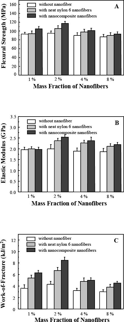
Mechanical properties: (A) flexural strength, (B) elastic modulus, and (C) work of fracture, of Bis-GMA/TEGDMA dental composites reinforced with various mass fractions of nanofibers. Each datum is the mean value of six measurements with the error bar representing one standard deviation.
The representative fracture surfaces of the control sample and the dental composites reinforced with 2 % (mass fraction) nanofibers are shown in Fig. 7A and B, respectively. The fracture surface of the control sample was smooth and had relatively large fracture steps, indicating little resistance to the applied force during breaking. The fracture surface of the nanofiber reinforced composite, on the other hand, was very rough, suggesting that nanofibers could deflect the crack. When the crack finally broke away from the nanofibers, numerous fracture lines and steps were created on the fracture surface, suggesting the energy consumption during breaking. No distinguishable difference could be identified between the composites reinforced with neat nylon 6 nanofibers and the ones reinforced with nylon 6/fibrillar silicate nanocomposite nanofibers using low magnification SEM images of the fracture surfaces. High magnification SEM images (Fig. 8), however, did show the difference. The presence of resin remnants on the ends of the pullout nanofibers was rarely observed for the neat nylon 6 nanofiber reinforced composites (see Fig. 8A); while the presence of such resin remnants was commonly found in the nylon 6/fibrillar silicate nanocomposite nanofiber reinforced composites (see Fig. 8B). This indicated that, besides strengthening the nanofibers, the silanized fibrillar silicate single crystals also enhanced the interfacial bonding between the nanofiber filler and the dental resin matrix. Presumably, this was because some of the silanized single crystals on the surface of nanocomposite nanofibers formed strong intermolecular interaction/bonding with the Bis-GMA/TEGDMA dental resin. There are two possible reasons accounted for the mechanical properties of the dental composites reinforced with nylon 6/fibrillar silicate nanocomposite nanofibers being generally higher than those reinforced with neat nylon 6 nanofibers (as shown in Fig. 6 A, B and C). These two reasons are: (1) the uniform distribution of nano-scaled and highly aligned fibrillar silicate single crystals in nylon 6 improved the mechanical properties of nanofibers; and (2) the silanized fibrillar silicate single crystals, particularly the ones on the surface of the nylon 6/fibrillar silicate nanocomposite nanofibers, enhanced the interfacial bonding between the nanofiber filler and the dental resin matrix.
Figure 7.
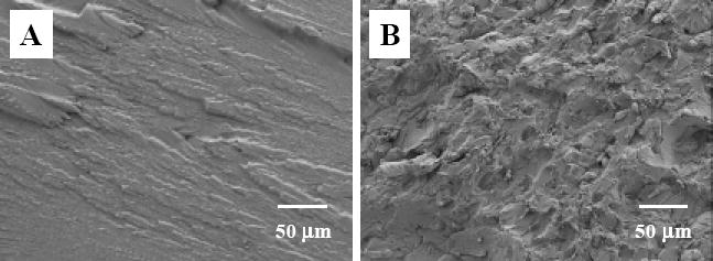
Low magnification SEM images showing the representative fracture surfaces of three-point flexural testing specimens: (A) the control sample, (B) Bis-GMA/TEGDMA dental composite reinforced with 2.0 % (mass faction) nanofibers.
Figure 8.
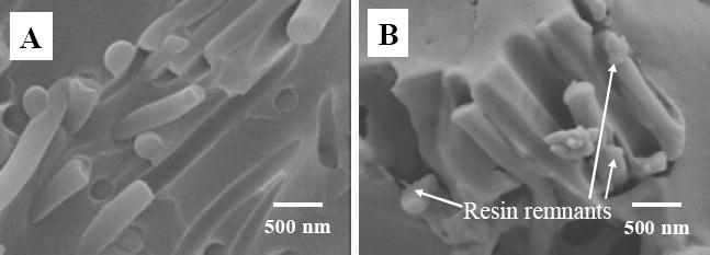
High magnification SEM images showing (A) neat nylon 6 nanofibers, and (B) nylon 6/fibrillar silicate nanocomposite nanofibers on the fracture surfaces of three-point flexural testing specimens.
Mechanical properties of the dental composites with larger mass fractions (4 % and 8 %) of nanofibers were, however, less desired. There are two possible explanations: (1) Since the mass fraction of (nylon 6 or nylon 6/fibrillar silicate nanocomposite) nanofibers in the prepared powders was set at a certain value (mass fraction of 20 %), larger mass fractions of nanofibers in the composites required larger mass fractions of powders in the dental pastes; such a condition increased the amounts of voids/defects in the final dental composites and resulted in reduction on mechanical properties. (2) The improvement of mechanical properties of the dental composites might be limited by both the mechanical properties of nanofibers and the interfacial bonding strength between the nanofiber filler and the dental resin matrix. Although the impregnation of nano-scaled and highly aligned fibrillar silicate single crystals into nylon 6 nanofibers improved the mechanical properties of the resulting nanocomposite nanofibers, the nylon 6/fibrillar silicate nanocomposite nanofibers were still not strong enough to effective reinforce dental composites. In order to achieve better reinforcement, the electrospun nanofibers may need to be collected as a highly aligned yarn instead of an almost randomly distributed felt so that the post-electrospinning stretching process could be applied to further improve the mechanical properties.
SUMMARY
The objective of this research was to study the reinforcement of electrospun nylon 6/fibrillar silicate nanocomposite nanofibers on Bis-GMA/TEGDMA dental composites. The hypothesis was that the uniform distribution of nano-scaled and highly aligned fibrillar silicate single crystals into nylon 6 nanofibers would improve the mechanical properties of the resulting nanocomposite nanofibers, and would further lead to effective reinforcement of dental composites. During this research, instead of being impregnated layer by layer, the electrospun nylon 6/fibrillar silicate nanocomposite nanofiber felt was first soaked with CQ/4EDMAB activated Bis-GMA/TEGDMA monomers; after the soaked felt was photo-cured, the obtained composite was then milled into a powder; subsequently, the powder was mixed with CQ/4EDMAB activated Bis-GMA/TEGDMA monomers to prepare dental pastes containing nanofibers of various mass fractions (1 %, 2 %, 4 % and 8 %); finally, the pastes were photo-cured, and the fabricated dental composites were characterized and evaluated. The powders without nanofiber and/or with neat nylon 6 nanofibers were also prepared and used to fabricate dental composites for comparison as control samples.
The prepared nylon 6/fibrillar silicate nanocomposite nanofibers had diameters ranging from 100 to 400 nm with the average diameter around 250 nm. The collected nanofiber felt had a thickness around 100 μm and a mass per unit area of approximately 60 g/m2. The nanofibers had a regular cylindrical shape with no beads and/or beaded nanofibers identifiable using SEM. POM and XRD results suggested that the nanofibers were highly crystalline and were structurally oriented. TEM images indicated that the silanized fibrillar silicate single crystals were uniformly distributed and highly aligned in the electrospun nanocomposite nanofibers. This supported the belief that the nanofibers were mechanically strong. Additionally, the small diameter of nanofibers also provided for a high surface area to volume ratio, which enhanced the intermolecular hydrogen bonding between the filler of nanofibers and the matrix of Bis-GMA/TEGDMA dental resin, resulting in a good interfacial bonding strength in the dental composites.
The mechanical properties of the nanofiber reinforced Bis-GMA/TEGDMA (50/50 mass ratio) dental composites were tested using a standard three-point flexural method. The results indicated that flexural strength (SF) elastic modulus (EY) and work of fracture (WOF) of the composites were substantially higher after being impregnated small mass fractions (1 % and 2 %) of nanofibers. The addition of 2 % nylon 6/fibrillar silicate nanocomposite nanofiber into the resin improved SF by 23 %, EY by 25 %, and WOF by 98 %. Low magnification SEM examinations revealed that the fracture surfaces of the nanofiber reinforced composites were very rough, while the fracture surfaces of the control sample were smooth with much larger fracture steps. This suggests that the presence of nanofibers effectively deflected the crack. When the crack finally broke away from the nanofibers, numerous fracture lines and steps were created on the fracture surface, suggesting energy consumption during the break. High magnification SEM images revealed the rare presence of resin remnants on the ends of the pullout nanofibers for the neat nylon 6 nanofibers, while such remnants were commonly found for the nylon 6/fibrillar silicate nanocomposite nanofibers. This indicated that, besides strengthening the nanofibers, the silanized fibrillar silicate single crystals (particularly the ones on the surfaces of the nanofibers) also enhanced the interfacial bonding between the nanofiber and the dental resin. Mechanical properties of the dental composites with larger mass fractions (4 % and 8 %) of nanofibers were less desired. Presumably, this was because of two reasons: (1) formation of voids/defects in the dental composites and (2) limitations from the mechanical properties of the nylon 6/fibrillar silicate nanocomposite nanofibers and from the interfacial bonding strength between the nanofiber filler and the dental resin matrix. In order to achieve better reinforcement, the electrospun nanofibers may need to be collected as a highly aligned yarn instead of a randomly distributed felt so that the post-electrospinning stretching process could be applied to further improve the mechanical properties.
Acknowledgments
This research was supported by the “National Institute of Dental and Craniofacial Research” (R03 DE16042), and by the “Center for Accelerated Applications at the Nanoscale” and the “BioMedical Engineering Program” at the South Dakota School of Mines and Technology. The authors are grateful to Esstech Co. for providing the dental monomers of Bis-GMA and TEGDMA.
Footnotes
Publisher's Disclaimer: This is a PDF file of an unedited manuscript that has been accepted for publication. As a service to our customers we are providing this early version of the manuscript. The manuscript will undergo copyediting, typesetting, and review of the resulting proof before it is published in its final citable form. Please note that during the production process errorsmaybe discovered which could affect the content, and all legal disclaimers that apply to the journal pertain.
References
- 1.Bowen RL. Dental filling material comprising vinyl-silane treated fused silica and a binder consisting of the reaction product of bisphenol and glycidyl methacrylate. US Pa. 1962;3:066,112. [Google Scholar]
- 2.Bowen RL. Properties of a silica-reinforced polymer for dental restoration. J Am Dent Assoc. 1963;66:57–64. doi: 10.14219/jada.archive.1963.0010. [DOI] [PubMed] [Google Scholar]
- 3.Antonucci JM, Stansbury JW. Molecular designed dental polymer. In: Arshady R, editor. Desk reference of functional polymers: Synthesis and application. American Chemical Society Publication. 1997:719–738. [Google Scholar]
- 4.Reed BB, Choi K, Dickens SH, Stansbury JW. Effect of resin composition of kinetics of dimethacrylate photopolymerization. Polym Prep. 1997;38(2):108–109. [Google Scholar]
- 5.Leinfelder KF, Sluder TB, Santos JFF, Wall JT. Five-year clinical evaluation of anterior and posterior restorations of composite resin. Oper Dent. 1980;12:52–78. [Google Scholar]
- 6.Abell AK, Leinfelder KF, Turner DT. Microscopic observations of the wear of a tooth restorative composite in vivo. J Biomed Mat Res. 1983;17(3):501–507. doi: 10.1002/jbm.820170309. [DOI] [PubMed] [Google Scholar]
- 7.Lacy AM. A critical look at posterior composite restorations. J Am Dent Assoc. 1987;114:357–362. doi: 10.14219/jada.archive.1987.0077. [DOI] [PubMed] [Google Scholar]
- 8.Jordan RE, Suzuki M. Posterior composite restorations. J Am Dent Assoc. 1991;122:31–37. doi: 10.14219/jada.archive.1991.0321. [DOI] [PubMed] [Google Scholar]
- 9.Corbin SB, Kohn WG. The benefits and risks of dental amalgam. J Am Dent Assoc. 1994;125:381–388. doi: 10.14219/jada.archive.1994.0055. [DOI] [PubMed] [Google Scholar]
- 10.Berry TG, Nicholson J, Troendle K. Almost two centuries with amalgam, where are we today? J Am Dent Assoc. 1994;125:392–399. doi: 10.14219/jada.archive.1994.0053. [DOI] [PubMed] [Google Scholar]
- 11.Fong H. Electrospun nylon6 nanofiber reinforced Bis-GMA/TEGDMA dental restorative composite resins. Polymer. 2004;45:2427–2432. [Google Scholar]
- 12.Reneker DH, Chun I. Nanometer diameter fibers of polymer, produced by electrospinning. Nanotechnology. 1996;7:216–223. [Google Scholar]
- 13.Fong H, Reneker DH. Electrospinning and formation of nanofibers (Chapter 6) In: Salem DR, editor. Structure formation in polymeric fibers. Hanser Gardner; Cincinnati, Ohio: 2001. pp. 225–246. [Google Scholar]
- 14.Huang Z, Zhang Y, Kotaki M, Ramakrishna S. A review on polymer nanofibers by electrospinning and their applications in nanocomposites. Composites Sci and Technology. 2003;63:2223–2253. [Google Scholar]
- 15.Fong H. Electrospun polymer, ceramic, carbon/graphite nanofibers and their applications (Chapter 11) In: Nalwa HS, editor. Polymeric nanostructures and their applications. Vol. 2. American Scientific Publishers; Stevenson Ranch, California: 2007. pp. 451–474. [Google Scholar]
- 16.Reneker DH, Yarin AL, Fong H, Koombhongse S. Bending instability of electrically charged liquid jets of polymer solutions in electrospinning. J Appl Phys. 2000;87(9):4531–4547. [Google Scholar]
- 17.Lai S, Li T, Liu X, Lv R. A study on the friction and wear behavior of PTFE filled with acid treated nano-attapulgite. Macromolecular Materials and Engineering. 2004;289:916–922. [Google Scholar]
- 18.Tian M, Qu C, Feng Y, Zhang L. Structure and properties of fibrillar silicate/SBR composites by blend process. J Mater Sci. 2003;38:4917–4924. [Google Scholar]
- 19.Tian M, Liang W, Rao G, Zhang L, Guo C. Surface modification of fibrillar silicate and its reinforcing mechanism on FS/rubber composites. Composites Science and Technology. 2005;65:1129–1138. [Google Scholar]
- 20.Chowdhury SR, Kar S, Ha CS. Polymer nanocomposites: a promising class of materials for a wide range of applications (Chapter 4) In: Nalwa HS, editor. Polymeric nanostructures and their applications. Vol. 2. American Scientific Publishers; Stevenson Ranch, California: 2007. pp. 201–242. [Google Scholar]
- 21.Fong H, Chun I, Reneker DH. Beaded nanofibers formed during electrospinning. Polymer. 1999;40:4585–4592. [Google Scholar]
- 22.Murthy NS, Aharoni SM, Szollosi AB. Stability of the γ form and the development of the α form in nylon 6. J. Polym Sci, Polym Phys Ed. 1985;23(12):2549–2565. [Google Scholar]
- 23.Alexander AE. X-ray diffraction methods in polymer science. Wiley-Interscience; New York: 1969. [Google Scholar]