

Abstract
Purpose:
To develop and test a method for automatically calculating the in-plane rotation for doubly-oblique slice geometry in order to minimize wrap artifacts for a given FOV.
Materials and Methods:
The equations for in-plane rotation were formulated for doubly-oblique imaging of a cylindrical body with elliptical cross-section. Based on this formulation, automatic in-plane rotation was implemented and tested on a commercial scanner using nominal values for ellipticity of the body.
Results:
Short axis, doubly oblique, cardiac imaging were acquired with and without in-plane rotation. The desired in-plane rotation proved to be relatively insensitive to the ellipticity of the body, permitting an automatic solution based on a nominal value.
Conclusion:
In-plane rotation is desirable for doubly oblique imaging (e.g., cardiac applications), particularly for reduced-FOV accelerated imaging such as SENSE. The proposed method, which provides an approximate solution for automatic, in-plane rotation for doubly-oblique imaging, was demonstrated. Published 2003 Wiley-Liss, Inc.†
Keywords: MRI, oblique, in-plane rotation, cardiac imaging, SENSE
A METHOD IS PROPOSED FOR automatically calculating the in-plane rotation for doubly-oblique slice geometry. Doubly-oblique slice orientation is commonly used in applications such as cardiac imaging, and results in an in-plane rotation of the body cross-section. For torso imaging with oblique geometry, the body cross-section is approximately elliptical, with major and minor axes and ellipticity in the approximate range of 1.5–2.5. It is often desirable to adjust the in-plane orientation for frequency encoding (readout) along the major axis and to adjust the phase encoding along the minor axis to ensure a minimum alias-free field-of-view (FOV) in the phase-encoding direction. In other words, with the proper in-plane rotation, the FOV in the phase encoding direction may be reduced to the minor axis dimension. This is particularly important for reduced FOV imaging, such as UNFOLD (1) or parallel MR methods, SENSE (2), or SMASH (3), as well as general imaging with an asymmetric FOV.
An example illustrating the in-plane rotation problem for an oblique imaging plane is shown in Figure 1. A body ellipse (with ellipticity = 2) is intersected by a doubly-oblique plane with normal vector, n = [1, 1, 1], resulting in the ellipse shown in bold in Figure 1, which has an in-plane rotation of θ = 23° in the plane defined by the box labeled “a.” After in-plane rotation, the plane defined by the box labeled “b,” with the same dimensions, is aligned with the body ellipse and will not have wrap artifacts for phase encoding along the minor axis direction.
Figure 1.

Illustration of doubly-oblique imaging plane intersecting an elliptical cylinder resulting in an ellipse (bold) with in-plane rotation (plane a), which may be rotated for minimum alias-free FOV (plane b) with phase encoding direction along minor axis dimension.
MATERIALS AND METHODS
Description and Theory
A doubly-oblique imaging plane is generally specified by its normal vector n = [nx, ny, nz]T (the superscript T denotes transpose) or its rotation matrix (M), and is typically prescribed graphically. Consider the body to be an elliptical cylinder. The intersection of an oblique plane through the origin, defined by the equation:
| (1) |
where r = [x, y, z]T, and an elliptical cylinder defined by the equation:
| (2) |
with major and minor axes defined by L and S, respectively, is an ellipse in the oblique plane. Without loss of generality, a centered ellipse is considered in this formulation. The angle of rotation for an off-centered ellipse will be the same as a centered ellipse, although there will be a translation. The derivation of the in-plane rotation angle ϑ follows. Let (x, y, z) be the body coordinate system and (x1, y1, z1) be an arbitrary coordinate system such that z1 = 0 for all points in the scan plane. If the oblique plane coordinates are transformed from the body coordinates (x, y, z) into (x1, y1, z1), then the ellipse parameters in (x1, y1) may be derived as follows. Let the coordinate transformation from r = [x, y, z]T into r1 = [x1, y1, z1]T be defined by the matrix rotation
| (3) |
Then the ellipse in (x1, y1) may be found by substituting into Eq. [2] as:
| (4) |
with z1 = 0, mij elements of rotation matrix M, and with the coefficients, A, B, and C, derived as:
| (5) |
The ellipse in (x1, y1) is rotated by the angle ϑ and has major and minor axes defined as L′ and S′. A new coordinate system (x2, y2, z2), for which the in-plane ellipse rotation has been optimized, is defined by:
| (6) |
Then substituting Eq. [6] into Eq. [4] for the ellipse in (x1, y1) yields the ellipse in (x2, y2):
| (7) |
where the coefficients may be derived as:
| (8) |
with ellipse parameters calculated (by setting the cross-term coefficient b = 0) as:
| (9) |
Thus the in-plane rotation angle ϑ is calculated in terms of the body major and minor axis dimensions (L and S). It is further shown by substitution that the angle ϑ is determined solely by the ellipticity (ratio) e = L/S and the rotation matrix M.
Recalling the example illustrated in Figure 1, the sensitivity of in-plane rotation to ellipticity is calculated for the specific rotation matrix with n = [1, 1, 1]. For e > 2.0, the rotation angle shown in Figure 2 for n = [1, 1, 1] is very insensitive to the ellipticity (e) for a wide range of normal vector directions. Thus a good approximation to the in-plane rotation angle may be calculated automatically from the normal vector using a default value for e = 2.0, which will be within several degrees for a wide range of interest.
Figure 2.
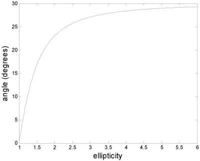
In-plane rotation angle vs. ellipticity for doubly-oblique plane with normal vector n = [1, 1, 1] illustrating insensitivity of angle for e > 2.
The rotation matrix M of the unoptimized imaging plane is the assumed starting point for the calculation of the desired in-plane rotation ϑ and is available to the pulse sequence from the scanner. This initial unoptimized rotation matrix M will depend on the localization procedure used to arrive at the desired oblique plane. The optimized matrix is then calculated with the procedure outlined above and is then subsequently used for imaging by the pulse sequence.
Experimental Parameters
Experiments were conducted using a GE Signa CV/i 1.5T MR imaging system. A standard pulse sequence was modified to incorporate the automatic in-plane rotation as a user-enabled option. The value for body ellipticity was set by default to e = 2.0, and could easily be modified by the user as a research control variable. Short axis cardiac imaging was performed using a gated-segmented fast gradient recalled echo (FGRE) sequence with 320 × 240 mm2 FOV. The doubly-oblique short-axis cardiac imaging plane was determined by a localization procedure as follows. A singly-oblique long-axis image was graphically prescribed from sagittal images that contained the heart. The doubly-oblique short-axis view was then prescribed from the resultant long-axis image. Doubly-oblique images were acquired with and without the automatic in-plane rotation.
RESULTS
Figure 3 shows example images of a single short-axis doubly-oblique cardiac image before (Fig. 3a) and after (Fig. 3b) in-plane rotation has been applied. In this example, the body ellipticity was approximately e = 2.0, the normal vector was [−0.48, 0.69, −0.55], and the rotation angle was calculated to be 34°. The sensitivity of in-plane rotation to the assumed ellipticity parameter will depend on the obliquity of the image plane and the unoptimized rotation matrix. The calculated value of in-plane rotation for various values of assumed ellipticity is plotted in Figure 4 from short-axis orientation data acquired from N = 72 patients. Note that several curves are very close and are not resolved in the plot.
Figure 3.

Example of doubly-oblique short-axis cardiac images before (a) and after (b) automatic in-plane rotation.
Figure 4.

In-plane rotation angle vs. ellipticity for various imaging plane orientations derived from N = 72 patient exams, illustrating insensitivity of angle for e > 2.
DISCUSSION
The above formulation approximates the body as an elliptical cylinder to derive an expression for the in-plane rotation. It has been found in practice that this assumption is not critical, since the calculated rotation is fairly insensitive to the ellipticity parameter, e, over a range of image plane orientations. The ellipticity of the torso, not including the shoulders or arms, was measured on 17 individuals using axial localizer images and found to be e = 1.5 ± 0.1 (mean ± SD). However, for cardiac imaging the slice often includes the shoulder as well. The ellipticity of the body, including the shoulder and arms, is estimated to be slightly greater than 2.0. Using this default value of ellipticity, the short-and long-axes of the resulting body cross-section are approximately aligned, thereby minimizing wrap, even though the cross-section is not actually an ellipse. The objectives of the automatic in-plane rotation to minimize the FOV in the phase encoding direction and eliminate wrap are considered to be met since the error is within 5°.
In-plane rotation is desirable for doubly-oblique imaging, e.g., cardiac applications, particularly for reduced FOV accelerated imaging such as SENSE. The proposed method provides an approximate solution, automatically eliminating the requirement for additional measurements. The automation of in-plane rotation reduces the time and experience required for proper localization. Another benefit is the elimination of alias artifacts, including wrap of arms and shoulders, since these features may be placed in the frequency readout direction. It should be noted that in-plane rotation will, in general, affect the minimally achievable TR for a given gradient performance (slew rate and maximum gradient).
This formulation for calculating in-plane rotation for oblique slice geometries may also be useful in field simulation of B1-maps such as those used for calculating parallel imaging performance (SENSE g-factor).
Footnotes
This paper was presented as a poster at the 11th Annual Meeting of ISMRM, Toronto, Canada, 2003.
This article is a US Government work and, as such, is in the public domain in the United States of America.
REFERENCES
- 1.Madore B, Glover GH, Pelc NJ. Unaliasing by Fourier encoding the overlaps using the temporal dimension (UNFOLD) applied to cardiac imaging and fMRI. Magn Reson Med. 1999;42:813–828. doi: 10.1002/(sici)1522-2594(199911)42:5<813::aid-mrm1>3.0.co;2-s. [DOI] [PubMed] [Google Scholar]
- 2.Pruessmann KP, Weiger M, Scheidegger MB, Boesiger P. SENSE: sensitivity encoding for fast MRI. Magn Reson Med. 1999;42:952–962. [PubMed] [Google Scholar]
- 3.Sodickson DK, Manning WJ. Simultaneous acquisition of spatial harmonics (SMASH): fast imaging with radiofrequency coil arrays. Magn Reson Med. 1997;38:591–603. doi: 10.1002/mrm.1910380414. [DOI] [PubMed] [Google Scholar]