Abstract
The aim of this study was to determine the effects of cyclic loading on the debond process of a roughened stem– cement interface used in total hip arthroplasty. The specific goals were to assess the effects of two surgeon-controlled variables (stem heating and degree of stem surface roughness) and to determine if an independent finite element-based fracture mechanics model could be used to predict the debond response. A clamped cantilever beam geometry was used to determine the fatigue debond response of the stem– cement interface and was created using an experimental mold that simulated in vivo cementing conditions. A second experiment was performed using a torsion-loading model representative of the stem– cement–bone composite. For both experiments, two stem heating (room temperature and 50°C) and surface roughness conditions (grit blasted: Ra = 2.3 and 5.1 μm) were used. Finally, a finite element model of the torsion experiment with provision for crack growth was developed and compared with the experimental results. Results from both experiments revealed that neither stem preheating nor use of a stem with a greater surface roughness had a marked effect on the fatigue debond response. There was substantial variability in the debond response for all cases; this may be due to microscopic gaps at the interface for all interface conditions. The debond rate from the finite element simulation (10−7.31 m/cycle) had a magnitude similar to the experimental torsion model (10− (6.77 ± 1.25) m/cycle). This suggests that within the context of the experimental conditions studied here that the debond response could be assessed using a linear elastic fracture mechanics-type approach.
Keywords: bone cement, PMMA, acrylic, computer modeling/simulation, fatigue, implant interface, hip prosthesis
INTRODUCTION
A primary cause of clinical loosening of cemented femoral components is the loss of fixation at the stem–cement interface. In an attempt to prevent this loss of fixation, stem surfaces are often roughened or precoated with cement to increase the bond strength of the interface.1,2 Rougher stem surfaces have the potential for greater mechanical interlock, thus increasing the strength of the interface. Preheating of the femoral stem is also credited with increasing the stem–cement bond3 because heating the stem causes polymerization to occur at the stem–cement interface first. This process forces voids from polymerization shrinkage4 to form further into the cement mantle and away from the interface,5 resulting in a potentially stronger interfacial bond.
Clinical reports of loosening rates for roughened stem surfaces have been mixed with several groups reporting poor outcomes6–8 while other groups find no clear difference between roughened and smooth (satin or polished) stem surfaces.9,10 To date, extensive clinical data does not exist with regards to loosening rates when stem preheating is used. Laboratory reports on the effectiveness of preheating in terms of increasing bond strength of the stem–cement interface have been inconsistent. Iesaka et al.3 found that stem preheating improved the metal–cement interfacial shear strength as determined by static and cyclic testing. They also reported a reduced porosity at the stem–cement interface when cementing with a preheated femoral stem. In contrast, while Wang et al.11 also found decreased porosity at the stem– cement interface with stem preheating, they found no significant correlation between porosity and static interfacial shear strength.
The modeling of debonding at interfaces has often been used in a finite element context where the interface is typically assumed to be bonded or completely failed.12 More recent efforts have focused on use of a strength of materials approach to modeling interface failure relying on static failure of the interface.13 Because of a paucity of data regarding the fatigue debond response of the stem–cement interface, there have been limited modeling efforts to predict fatigue failure at this interface. The two most convenient approaches to modeling fatigue failure are to use either a damage accumulation approach14 or a fatigue crack approach where the finite element mesh is modified to directly model the debonding process.15 In this study, a linear elastic fracture mechanics (LEFM) approach16 is used where a crack is introduced at the interface and the interface debond energy is determined experimentally after the load is applied to the specimen. The fatigue debond response is modeled using a Paris Law model,16 which has previously been shown to be appropriate for debonding of the stem– cement interface.17 The Paris Law parameters from the experiment are then used as input parameters for finite element simulation of the debond process.
We conducted a series of experiments and computer simulations in order to gain a greater understanding of the effects of cyclic loading on the debonding process at the roughened stem–cement interface and to examine the effects of surface finish and femoral stem preheating on the strength of this interface. First, a clamped cantilever beam experiment was utilized to determine the energy required to debond the stem–cement interface under conditions of varied stem temperature and stem surface roughness. Second, we investigated the debond response of the stem–cement interface for a more realistic experiment using a cross section of a cemented stem–cement construct under torsional loading. Finally, we applied the fatigue crack growth response data (via Paris Law parameters) from the clamped cantilever beam experiment to predict the debond response of the torsional-loading experiment using a finite element model with provision for interface debonding. We hypothesized that (1) the resistance to interface debonding would increase with use of a heated stem and high surface roughness, and (2) the debond response determined by the experimental and computational torsional-loading models would not be different.
MATERIALS AND METHODS
Clamped Cantilever Beam Experiment
A previously developed in vivo simulated mold was used to create stem– cement composites amenable to a clamped cantilever beam geometry.18 This mold was developed to provide mechanical and thermal boundary conditions that mimicked the conditions present during cementing of a femoral hip component. Cobalt chromium alloy (CoCr) stems consisted of a central square bar and two half-rounds that were bonded to the central bar to create a generic stem geometry [Figure 1(A)]. The bars were roughened with either 16 (average roughness, Ra = 5.1 μm) or 60 (Ra = 2.3 μm) grit aluminum oxide. Surface roughness was verified using a surface pro-filometer (Mitutoyo Corp., Ckanagawa, Japan). The surface roughness values of 16 and 60 grit were chosen to represent the range of commercially available grit-blasted surface finishes.1 An aluminum mold heated to 37°C was used to simulate the proximal femur. The mold had surface asperities to represent trabecular bone and to allow for interlock between the cement and cortical wall. PMMA cement (Simplex P, Stryker Orthopedics, Mahwah, NJ) was mixed for 1 min under vacuum and the mold was filled in a retrograde fashion. Stems were inserted either at room temperature (21°C) or at heated (50°C) conditions for 4 min from the initiation of mixing. The mantle construct was removed from the mold after 24 h and stored for 2 weeks in saline at 37°C. Cement in the half round regions was carefully machined and the half-rounds were removed, resulting in a clamped cantilever beam geometry [Figure 1(B)].
Figure 1.
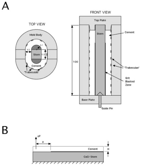
Top and side views of the in vivo simulated mold (A). The half-rounds are removed by careful machining of the cement, resulting in a clamped cantilever beam specimen (B). All dimensions are in millimeters.
Mechanical testing consisted of application of cyclic tensile loads using displacement-controlled loading at 2 Hz for the first 1000 cycles followed by loading at 5 Hz for the remainder of the experiment. The low loading rate early in the test was performed to capture rapid crack growth rates. Applied load (ΔP), crack length (a), and number of loading cycles (N) were sampled at prescribed intervals for data analysis. Crack length was monitored using a 45× traveling microscope. Using an elasticity solution for the compliance of a clamped cantilever beam,19 the cyclic debond energy (ΔG) was calculated using:
where E (2200 MPa) is the cement modulus, B (12.3 mm) is specimen depth, H (6.3 mm) is specimen height, and ν (0.3) is Poisson’s ratio. The fatigue response was plotted as fatigue debond rate (da/dN) versus ΔG. A Paris Law model (da/dN = C(ΔG)m)16 was fit to these two phases of the response, and the parameters “m” (log-slope) and “C” (log-intercept) were used for statistical comparison. A total of 16 specimens were tested, with four specimens at each grit (16 or 60)/heat (heated or room temperature) combination. All tests were conducted in 37°C deionized water.
Following testing, the porosity at the cement surface that had debonded from the stem was determined. Black modeling clay was spread into the pores to create contrast with the cement. Specimens were imaged using a 2 mega-pixel camera attached to a dissecting microscope and gap fraction was determined using Image J (Version 10.2).
Stem–Cement Torsion Experiment
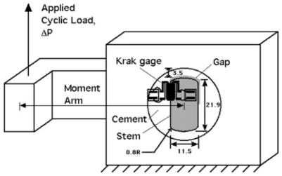
An idealized stem cross-section was created to investigate the debond response of the stem– cement interface when subjected to torsional loading (Figure 2). This model system was chosen to represent one of the primary mechanisms of loosening of stems: the axial torsional-loading component. Ten millimeter thick CoCr stem sections using a geometry with flat sides and rounded ends were grit-blasted with either 16 (Ra = 5.1 μm) or 60 (Ra = 2.3 μm) grit aluminum oxide. Test specimens were created using an aluminum mold into which the cement was introduced 4 min after the initiation of mixing.
Figure 2.
Experimental apparatus illustrating loading and crack length measurement for stem– cement torsion model. The stem/cement specimens are created in a separate mold and epoxied into an aluminum support ring. All dimensions are in millimeters.
For the heated stem case, the stem was heated to 50°C, while the outer aluminum mold ring (representing bone) was warmed to 37°C. With this condition, polymerization started at the stem and moved towards the mold ring. To simulate the room temperature stem case in terms of the polymerization front, we chose to cool the stem to 4°C while maintaining the aluminum mold ring at 37°C. This modification in protocol was done because of concern over influence of the top and bottom plates in the curing process, which were in close proximity to the curing cement mass because of the limited specimen height. The top and bottom mold plates were maintained at 21°C and to insure that the polymerization front would start first at the mold body and finish last at the stem surface, the stem was cooled below the 21°C level. In a preliminary study, the morphology of the resulting stem–cement interface for the heated stem and modified room temperature stem case using this approach were compared with the respective clamped cantilever beam cases to insure that they were similar.
After curing, the face of each specimen was sanded flat, and a small gap was introduced using a jewelers saw (0.7-mm thickness); this served as a controlled precrack. The gap was included to simulate the large gap regions that were found for grit-blasted stems in cadaver bones.20 The stem– cement specimens were epoxied into an aluminum fixture for mechanical loading. Crack gages (Krak-Gage, Hartrun Corp., St. Augustine, FL) were aligned with the stem– cement interface to monitor crack growth. Crack gages were not used in the clamped cantilever beam experiment because the location of initial debond was often difficult to predict and the debond length often extended far beyond the useable range of the crack gages (5 mm).
Mechanical testing consisted of cyclic torques (T = 7.38 N m over 10-mm specimen depth) applied via a moment arm using load control with an MTS machine (MTS Corp., Eden Prairie, MN) at 5 Hz. This load level was chosen as an estimate of the torsional load that might be transferred over a proximally grit-blasted region of a cemented stem. Here, we assume that all the load was transferred across the grit-blasted region. With a typical 50-mm length grit-blasted region, this would be equivalent to a torque of ~37 N m (0.738 N m/mm × 50 mm). This is within the range of axial torques reported in instrumented hips 24–40.3 N m.21 Specimens were tested in deionized water at 37°C to a maximum of 400,000 loading cycles. Saline was not used due to concern over the confounding effect of fluid conductivity on the function of the crack gage. Crack length (a) and number of loading cycles (N) were collected at regular intervals. A total of 24 fatigue tests were conducted, with six specimens at each grit (16 or 60) and heat (heated or cooled) condition.
Computational Methods
A plain strain, 2-D, finite element model (Figure 3) with provision for crack growth was created to simulate the stem–cement torsion experiment. A plain strain finite element model was chosen based on a preliminary calculation of specimen thickness needed to provide plane strain conditions at the crack tip16 and was estimated to be on the order of 0.2 mm. Given that our experimental specimen thickness was much larger than this (10 mm), it was determined that a plane strain model could be used to capture the behavior at the crack tip. A LEFM16 approach was used to assess crack growth along the stem– cement interface. Linear, elastic six-and eight-noded elements (651 elements, 1978 nodes after introduction of initial crack tip) were used for the stem (E = 200 GPa), cement (E = 2.2 GPa), and surrounding aluminum ring (E = 70 GPa). A couple was applied to achieve the same moment as was applied in the experiment using point loads on the stem. Care was taken to apply these point loads such that the local stress field near the crack tip was unaffected. This was not difficult because the stem was much more rigid than the cement. The outer edge of the aluminum ring was constrained. A crack was introduced along the stem– cement interface and propagated along the interface in several increments using the finite element package FRANC (Cornell Fracture Group, Ithaca, NY). Cyclic debond energy, ΔG, was determined as a function of crack length using the J-integral method along the bimaterial interface.22 A Paris Law model was then used to predict debond growth rate (da/dN) of the stem– cement torsion experiment with ΔG determined from the finite element model and Paris Law constants taken from the independent clamped cantilever beam experiment. Note that this model did not directly model surface roughness or cement porosity, but simulated the debond response using the Paris Law constants from the experiments.
Figure 3.
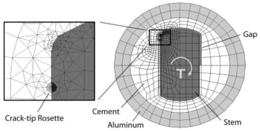
Finite element mesh of stem– cement cross-sectional model. Inset shows crack tip rosette.
RESULTS
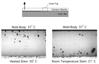
Observations of specimens from the clamped cantilever beam study revealed that voids tended to form near the mold side of the cement for the heated stem specimens and near the stem side for the room temperature specimens (Figure 4). Cement porosity was negligible for the heated stem specimens and (12 ± 5.7)% for the room temperature stem specimens.
Figure 4.
Void formation for heated and room temperature stems indicates that pores form near or on the stem surface with a room temperature stem (right), while pores form near the mold body for the heated stems (left).
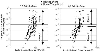
The fatigue loading regime for the clamped cantilever beams resulted in a wide range of crack growth rates from 10−2 to 10−9 m/cycle. The fatigue crack growth response (Figure 5) had two main components: a Phase I response characterized by a rapid drop in the fatigue crack growth rate, and a Phase II response characterized by a more moderate decrease in debond rate. A transition zone between phases occurred at ~10−5–10−6 m/cycle. There was substantial overlap in the debond response for all test combinations (Table I). ANOVA did not reveal any significant difference in Paris Law parameters as a function of temperature or surface roughness. Of note was the very large specimen-to-specimen variability for these test specimens. Given the lack of strong relationship between debond response and stem surface treatment, results from the 16 experiments were grouped to develop a single Paris Law response for the Phase I and Phase II data. There was a significant difference (p < 0.001) between the two phases for this grouped data.
Figure 5.
Debond extension rates for 16 and 60 grit surfaces using heated and room temperature stems as determined from the clamp cantilever beam experiments.
TABLE I.
Paris Law Parameters (m and c) for the Clamped Cantilever Beam Fatigue Debond Experiment
| Stem Conditiona |
|||||
|---|---|---|---|---|---|
| Paris Law Parameters | Grit 16/Heated | Grit 16/Room Temperature | Grit 60/Heated | Grit 60/Room Temperature | Grouped |
| m | |||||
| Phase I | 40.4 (17.6) | 38.1 (12.5) | 48.3 (58.8) | 37.7 (28.8) | 41.1 (31.1) |
| Phase II | 4.65 (2.00) | 6.35 (5.29) | 3.40 (1.38) | 4.40 (3.56) | 4.70 (3.25) |
| C | |||||
| Phase I | 10−74.0 (27.7) | 10−78.8 (25.2) | 10−83.4 (92.9) | 10−62.6 (33.5) | 10−74.7 (47.9) |
| Phase II | 10−14.0 (2.37) | 10−19.1 (10.7) | 10−11.5 (2.25) | 10−13.2 (4.79) | 10−14.5 (6.2) |
Data are derived using (ΔG) (J/m2) and da/dN (m/cycle).
Values in parentheses indicate standard deviation.
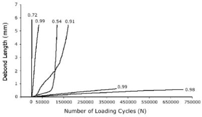
For the stem– cement torsion experiment, the crack length (a) versus loading cycle (N) response (Figure 6) was generally linear (r2 = 0.78 ± 0.20) for the 24 test specimens. Thus, debond growth rate (da/dN) was used to describe the debonding characteristics of the test specimens (Table II). Average cyclic debond rates were lowest for the heated/16 grit combination (10−7.48 m/cycle) and highest for the cooled/60 grit combination (10−5.93 m/cycle). However, neither surface finish (p = 0.11) nor stem temperature (p = 0.15) was found to be a significant independent variable as tested using ANOVA. The debonding of the stem– cement interface was again found to be highly variable for all grit/temperature combinations, reducing the statistical power of the experiments.
Figure 6.
Debond behavior from the stem– cement torsion experiment illustrating wide variability in response. Data are shown here for the 16 grit case with warm stem. Numbers above lines indicate linear regression fit (r2) values.
TABLE II.
Cyclic Debond Rate (da/dN, m/cycle) as Functions of Surface Roughness and Stem Temperature for the Stem–Cement Torsion Experiment
| Heated Stem | Cooled Stem | |
|---|---|---|
| 16 grit | 10(−7.48 ± 1.29) | 10(−6.87 ± 0.95) |
| 60 grit | 10(−6.79 ± 1.11) | 10(−5.93 ± 1.37) |
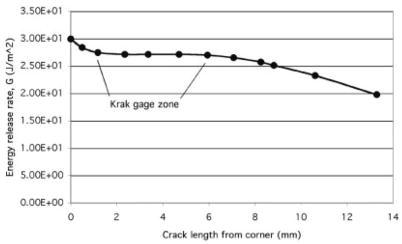
Results from the finite element analysis of the stem–cement torsion experiment indicated that the cyclic energy release rate was nearly constant (27.3 J/m2) over the region measured by the crack gage (Figure 7). Using the Phase II Paris Law constants (C and m) from the clamped cantilever beam tests, an average cyclic debond rate of 10−7.31 m/cycle was predicted for the model of the stem– cement torsion experiment. This was similar to the experimental results (10− (6.77 ± 1.25) m/cycle) determined for the stem– cement torsion specimens, indicating that the LEFM model was able to predict the response found in the experiment using input data from an independent experiment.
Figure 7.
Cyclic energy release rates determined from the finite element analysis of the stem– cement torsion experiment.
DISCUSSION
The results from both the clamped cantilever beam and stem–cement torsion experiments did not support our initial hypothesis that the fatigue debond response of the roughened stem–cement interface would be improved by preheating the stem and using a greater surface roughness. The voids that were present macroscopically at the stem–cement interface for the room temperature stems appear not to have an adverse affect on the fatigue debond response. In an attempt to understand why this may be so, scanning electron microscopy (SEM) images of the room temperature and heated stem–cement interfaces were obtained from specimens that had not been fatigue tested. The SEM images (Figure 8) indicate that microscopic gaps were present at the stem–cement interface in both heated and room temperature specimens. These could be due to local shrinkage upon cement curing or from local air entrapment. Nonetheless, the presence of these microscopic gaps may explain the lack of improvement in fatigue debond response for cases when the stem was heated.
Figure 8.
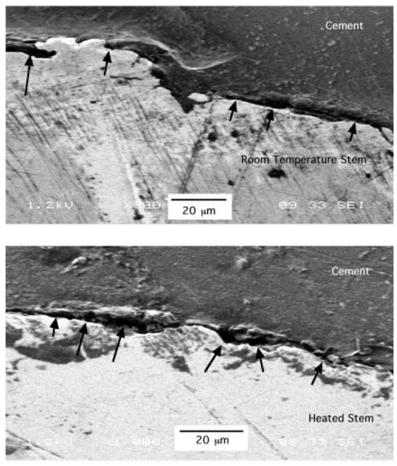
SEM images of room temperature and heated stem specimens, with the stem at the bottom and cement at the top of the image. Small gaps (10–50 μm in length) are evident at the stem–cement interface in both cases (indicated by arrows).
The results from the experiments/models support our second hypothesis that the debond response of the torsion model could be predicted using an LEFM/finite element model with fatigue debond data obtained from a completely different experiment. This suggests that within the context of the experimental conditions studied here that the debond response could be assessed using an LEFM-type approach. Other interface conditions that result in a large cohesive zone may not be amenable to this approach. One limitation of the torsion model/experiment was the fact that a gap was artifi-cially introduced at the stem– cement interface in the same location. As such, the experiment did not rely on the random gaps that have been found to form over grit-blasted surfaces.20 In the future, naturally occurring random gaps could be modeled directly, thereby allowing for determination of the debond response for a wide variety of conditions. This could be done by using a very fine mesh around the stem– cement interface, and randomly moving nodes away from the interface to create voids.
Preheating of the stem5 has been proposed as a mechanism to decrease porosity at the stem– cement interface. The approach used in the present study was able to control the polymerization path and the location of pore development, consistent with previous work. However, the results were not consistent with those of Iesaka et al.3 who found an increased push-out strength with preheating of the stem. The use of a push-out test may be more sensitive to the macro-porosity of the interface because the rough stem surface must be pushed past asperities in the cement. In contrast, the fracture mechanics approach here only relies on the local separation of the interface, and failure occurs by the progressive debonding of the interface with little post-failure contact. As loading across the interface is complex and varies with location and loading condition, both failure conditions (with and without post debonding contact) are probably important in determining the fate of the cemented implant.
To date, clinical results using preheated stems have not been reported; therefore, it is difficult to determine if preheating the stem will reduce the loosening rates of cemented stems. Preheating has other benefits such as reduced operating room time due to faster overall cement polymerization23 and the reduction of local stress risers (pores) in the cement adjacent to the stem. Therefore, even though substantial improvements from preheating of the grit-blasted components was not found here, the use of the technique may have other benefits. One possible limitation with preheating of the stem is the possibility of increasing the temperature at the cement–bone interface, thereby increasing the risk of thermal necrosis. Iesaka et al.3 have measured an increased temperature of 6°C at the bone–cement interface. Whether this is sufficient to cause damage in an in vivo environment where there is blood circulation is unclear.
When compared with smooth stems, roughening of the stem surface results in an increase in debond strength.1,11,24 However, it appears that the debond strength can also depend to a great extent on the fabrication method.18 Gap and pore formation is more likely to occur at the stem–cement interface when using grit-blasted stems when compared with satin finished stems.20 These gaps could serve as initiation sites for debonding; the torsion experiment presented here was designed to simulate this effect. Of concern in the present study was the wide variability in debond rates with these carefully fabricated and controlled experimental specimens. This suggests that, in a clinical environment where cementing procedures are highly variable, there may be wide variability in the integrity of the stem–cement interface when a grit-blasted stem is used. From a clinical perspective, loss of fixation between a roughened stem and cement may be particularly problematic because rough stems are thought to potentially generate particulate debris that could induce an osteolytic effect resulting in bone loss and loosening of the implant from the bone.25
There are conflicting results in the current literature regarding the clinical effectiveness using roughened stems in total hip arthroplasty. Several studies point to poor clinical outcomes when grit-blasted stems were used with failure often described to include stem–cement debonding, bone–cement loosening, and focal osteolysis possibly due to debris generation from the debonded rough stem.6–8 However, there are several other studies in which failure rates were the same for roughened and smooth stems where difference in surface finish was the only variable.9,10 These contradictions are most likely due to the fact that the failure process is multifactorial and that the condition of the cement mantle including mantle thickness and porosity, patient weight, stem geometry, and other surgical factors may all contribute to whether an implant system fails.25–27
Acknowledgments
The authors thank Dr. Jeremy Gilbert for assisting with the scanning electron microscope images presented in this study.
Footnotes
Contract grant sponsor: NIH/NIAMS; contract grant number: AR42017; Contract grant sponsor: Stryker Orthopedics, Inc.
References
- 1.Crowninshield RD, Jennings JD, Laurent ML, Maloney WJ. Cemented femoral component surface finish mechanics. Clin Or-thop Rel Res. 1998;355:90–102. doi: 10.1097/00003086-199810000-00010. [DOI] [PubMed] [Google Scholar]
- 2.Huiskes R, Verdonschot N, Nivbrant B. Migration, stem shape, and surface finish in cemented total hip arthroplasty. Clin Or-thop Rel Res. 1998;355:103–112. doi: 10.1097/00003086-199810000-00011. [DOI] [PubMed] [Google Scholar]
- 3.Iesaka K, Jaffe WL, Kummer FJ. Effects of preheating of hip prostheses on the stem– cement interface. J Bone Joint Surg Am. 2003;85A:421– 427. doi: 10.2106/00004623-200303000-00003. [DOI] [PubMed] [Google Scholar]
- 4.Gilbert JL, Hasenwinkel JM, Wixson RL, Lautenschlager EP. A theoretical and experimental analysis of polymerization shrinkage of bone cement: A potential major source of porosity. J Biomed Mat Res. 2000;52:210–218. doi: 10.1002/1097-4636(200010)52:1<210::aid-jbm27>3.0.co;2-r. [DOI] [PubMed] [Google Scholar]
- 5.Bishop NE, Ferguson S, Tepic S. Porosity reduction in bone cement at the cement–stem interface. J Bone Jnt Surg. 1996;78B:349–357. [PubMed] [Google Scholar]
- 6.Collis DK, Mohler CG. Loosening rates and bone lysis with rough finished and polished stems. Clin Orthop Rel Res. 1998;355:113–122. doi: 10.1097/00003086-199810000-00012. [DOI] [PubMed] [Google Scholar]
- 7.Della Valle AMG, Zoppi A, Peterson MGE, Salvati EA. Surface finish affects the clinical and radiographic performance of a modern cemented femoral stem. In: Surgeons AAoO., editor. 2005 Annual Meeting. Washington, D.C: American Academy of Orthopaedic Surgeons; p. P028. [Google Scholar]
- 8.Ong A, Wong KL, Lai M, Garino JP, Steinberg ME. Early failure of precoated femoral components in primary total hip arthroplasty. J Bone Joint Surg Am. 2002;84A:786–792. doi: 10.2106/00004623-200205000-00014. [DOI] [PubMed] [Google Scholar]
- 9.Rasquinha VJ, Ranawat CS, Dua V, Ranawat AS, Rodriguez JA. A prospective, randomized, double-blind study of smooth versus rough stems using cement fixation: Minimum 5-year follow-up. J Arthroplasty. 2004;19(Suppl 2):2–9. doi: 10.1016/j.arth.2004.06.005. [DOI] [PubMed] [Google Scholar]
- 10.Vail TP, Goetz D, Tanzer M, Fisher DA, Mohler CG, Callaghan JJ. A prospective randomized trial of cemented femoral components with polished versus grit-blasted surface finish and identical stem geometry. J Arthroplasty. 2003;18(Suppl 1):95–102. doi: 10.1016/s0883-5403(03)00298-5. [DOI] [PubMed] [Google Scholar]
- 11.Wang JS, Taylor M, Flivik G, Lidgren L. Factors affecting the static shear strength of the prosthetic stem– bone cement interface. J Mater Sci Mater Med. 2003;14:55– 61. doi: 10.1023/a:1021501520479. [DOI] [PubMed] [Google Scholar]
- 12.Harrigan TP, Harris WH. A three-dimensional non-linear finite element study of the effect of cement-prosthesis debonding in cemented femoral total hip components. J Biomech. 1991;24:1047–1058. doi: 10.1016/0021-9290(91)90021-e. [DOI] [PubMed] [Google Scholar]
- 13.Verdonschot N, Huiskes R. Cement debonding process of total hip arthroplasty stems. Clin Orthop Relat Res. 1997;336:297–307. doi: 10.1097/00003086-199703000-00038. [DOI] [PubMed] [Google Scholar]
- 14.Stolk J, Verdonschot N, Murphy BP, Pendergast PJ, Huiskes R. Finite element stimulation of anisotropic damage accumulation and creep in acrylic bone cement. Engr Fract Mech. 2004;71:513–528. [Google Scholar]
- 15.Hertzler J, Miller MA, Mann KA. Fatigue crack growth rate does not depend on mantle thickness: An idealized cemented stem constructed under torsional loading. J Orthop Res. 2002;20:676– 682. doi: 10.1016/S0736-0266(02)00004-9. [DOI] [PubMed] [Google Scholar]
- 16.Broek D. Elementary Engineering Fracture Mechanics. Boston: Kluwer Academic; 1991. [Google Scholar]
- 17.Heuer DA, Mann KA. Fatigue fracture of the stem– cement interface with a clamped cantilever beam test. J Biomech Eng. 2000;122:647– 651. doi: 10.1115/1.1322035. [DOI] [PubMed] [Google Scholar]
- 18.Mann KA, Damron LA, Race A, Ayers DC. Early cementing does not increase debond energy of grit blasted interfaces. J Orthop Res. 2004;22:822–827. doi: 10.1016/j.orthres.2003.12.014. [DOI] [PubMed] [Google Scholar]
- 19.Ugural AC, Fenster SK. Advanced Strength and Applied Elasticity. New York: Elsevier; 1986. [Google Scholar]
- 20.Race A, Miller MA, Ayers DC, Cleary RJ, Mann KA. The influence of surface roughness on stem– cement gaps. J Bone Jnt Surg. 2002;84B:1199–1204. doi: 10.1302/0301-620x.84b8.12598. [DOI] [PubMed] [Google Scholar]
- 21.Bergmann G, Graichen F, Rohlmann A. Hip joint loading during walking and running, measured in two patients. J Bio-mech. 1993;26:969–990. doi: 10.1016/0021-9290(93)90058-m. [DOI] [PubMed] [Google Scholar]
- 22.Kanninen MF, Popelar CH. Advanced Fracture Mechanics. New York: Oxford University Press; 1985. [Google Scholar]
- 23.Dall DM, Miles AW, Juby G. Accelerated polymerization of acrylic bone cement using preheated implants. Clin Orthop Relat Res. 1986;211:148–150. [PubMed] [Google Scholar]
- 24.Ohashi KL, Romero AC, McGowan PD, Maloney WJ, Dauskardt RH. Adhesion and reliability of interfaces in cemented total hip arthroplasties. J Orthop Res. 1998;16:705–714. doi: 10.1002/jor.1100160612. [DOI] [PubMed] [Google Scholar]
- 25.Schmalzried TP, Zahiri CA, Woolson ST. The significance of stem– cement loosening of grit-blasted femoral components. Orthopedics. 2000;23:1157–1164. doi: 10.3928/0147-7447-20001101-14. [DOI] [PubMed] [Google Scholar]
- 26.Cannestra VP, Berger RA, Quigley LR, Jacobs JJ, Rosenberg AG, Galante JO. Hybrid total hip arthroplasty with a precoated offset stem. Four to nine-year results. J Bone Joint Surg Am. 2000;82:1291–1299. doi: 10.2106/00004623-200009000-00009. [DOI] [PubMed] [Google Scholar]
- 27.Harris WH. Long term results of cemented femoral stems with roughened precoated surfaces. Clin Ortop Rel Res. 1998;355:137–143. doi: 10.1097/00003086-199810000-00014. [DOI] [PubMed] [Google Scholar]


