

Abstract
The study and the exploitation of membrane proteins for drug screening applications requires a controllable and reliable method for their delivery into an artificial suspended membrane platform based on lab-on-a-chip technology. In this work, a polymeric device for forming lipid bilayers suitable for electrophysiology studies and biosensor applications is presented. The chip supports a single bilayer and is configured for controlled protein delivery through on-chip microfluidics. In order to demonstrate the principle of protein delivery, the potassium channel KcsA was reconstituted into proteoliposomes, which were then fused with the suspended bilayer on-chip. Fusion of single proteoliposomes with the membrane was identified electrically. Single channel conductance measurements of KcsA in the on-chip bilayer were recorded and these were compared to previously published data obtained with a conventional planar bilayer system.
Introduction
Ion channels are of considerable importance in biological cell membranes for many reasons, including the regulation of ion concentrations involved in electrical signalling within nerve, muscle and other living cells. Moreover, ion channels exhibit a number of distinctive characteristics, including highly specific, ion-selective filtering, where control and activation is through a variety of mechanisms, depending upon the function and nature of the cell.1,2
Ion channels thus have the potential for use as extremely specific, sensitive biosensors and for use in drug screening technologies3,4 by exploiting transmembrane ion movement in an artificial and controlled environment.5-7 These properties would be especially beneficial if channels were integrated into a lipid bilayer membrane system within a microfluidic chip architecture, thus reproducing the natural environment of the protein and combining the advantages of electronic and optical recording, microfluidics and automated control.8-11
In recent decades, numerous investigations on ion channel behaviour have been reported, including studies on gating mechanisms and channel selectivity,12,13 primarily by means of two main approaches: patch-clamp14-17 and black lipid membrane (BLM) techniques.18-23 Both methods are widely used to probe the electrical and chemical functionality of ion channels.
There are many advantages in developing an on-chip BLM technology. For instance, simultaneous electrical and optical measurement of fluorescently labelled ion channels can be performed, providing information about conformational changes24 and protein functionality.11 However, a number of technological issues have to be addressed if this technology is to be adopted, particularly in terms of reliability and semi-automation of the process. Currently, a high degree of manual expertise is required to form an artificial membrane either on conventional apparatus or on-chip. Even when microfabricated structures are used, BLMs are still commonly still made either by painting lipid with a rod over the device aperture,25,26 or by alternative techniques where manual intervention is required (i.e. removal of excess lipid solution with cotton).22 BLMs have also been made within microfluidic chips using solvent extraction through a polydimethylsiloxane (PDMS) microfluidic channel, although this technique is not yet fully developed.23
Patch-clamp techniques measure protein behaviour in the native cell and therefore obviate the requirement for protein over-expression and reconstitution. In the conventional method, immobile single cells are patched with a glass pipette. Recent chip-based methods require single cells to be sucked over and onto a micro-aperture to form a tight seal between the membrane and the orifice.14,17 This process requires human skill and expertise, and activation of a single channel gating mechanism is not always easy to achieve.16 In view of the advantages of chip-based systems, a number of research groups are developing semi-automated patch-clamp arrays based on microfluidic platforms,14-17 but few results on single channel measurement have been published.
The artificial BLM approach offers a valuable alternative to the patch-clamp method: it does not require live cells, but does require adequate supplies of functionally active proteins. Generally, large proteins (50-500 kDa) do not reliably self-insert into membranes (with the exception of the medium sized OmpF and α-hemolysin (approximately 35 kDa))19,27 in the way that small fusogenic peptides do (e.g., gramicidin, alamethicin and valinomycin).22,25 Therefore, a reliable method for controlled delivery and fusion of functionally active proteins into suspended bilayer membranes is required. This is one of the main issues facing the development of BLM, chip-based, drug screening systems.
In this paper, we describe the formation of BLMs within a microfluidic chip and a technique for delivering membrane proteins to the bilayer. To demonstrate this, the potassium channel KcsA (MW 67 kDa for the tetrameric form) was successfully delivered to an on-chip BLM using a vesicle fusion technique, which was optimised for the chip-system. The method is simple and reliable and could be implemented within a generic single molecule biosensing platform. The aim of this work was to develop a system for on-chip electrophysiology, using proteoliposome fusion to incorporate large proteins into a BLM within a microfluidic device.
Protein delivery to bilayer membrane
A proteoliposome is a unilamellar lipid vesicle into which protein molecules have been reconstituted. These vesicles have been used for ion channel delivery into bilayer membranes by many authors.28,29 From 1980 onwards, several delivery techniques have been optimised, and a range of parameters identified as important for inducing the vesicles to fuse with a membrane.30-33 Amongst these, a salt gradient across the membrane and a means for moving vesicles towards the bilayer membrane play an important role.
Conventional technique
In the conventional approach, proteoliposomes are fused with a suspended lipid bilayer by creating a salt gradient across the membrane.32,34 If protein electrical activity is not seen after vesicle injection, the BLM is either broken and reformed35 or a solution of the proteoliposomes is painted directly onto the aperture using a rod.36 Generally, these procedures lead to protein incorporation and the appearance of channel activity either immediately or within a few minutes.37 However, these methods are not particularly amenable to chip-based systems.
Nystatin–ergosterol (N/E) technique
In 1990, Woodbury and Miller proposed an improved method for vesicle fusion, which also enabled electrical detection of fusion events.38 This technique meant that it was possible to estimate the number of functionally reconstituted channel proteins in the BLM. In this method, the proteoliposomes contain nystatin (a trans membrane antibiotic) and ergosterol (a plant sterol). The vesicles are introduced into the cis compartment of an ergosterol-free bilayer, across which a salt gradient has been established. The higher salt concentration (typically 450 to 600 mM) is on the cis side (where the vesicles are added), with a lower salt concentration (150 mM) on the trans side.
The cis side is continuously stirred, inducing the vesicles to randomly collide with the bilayer. When the liposomes contact the BLM, they are subjected to a positive hydrostatic pressure, caused by an efflux of water from the trans side (low salt), through the BLM and therefore into the vesicle. This induces swelling and stressing of the liposome, leading to fusion with the membrane.40 The nystatin and ergosterol forms a complex within the vesicle (Fig 1a) creating electrically conducting pores. When a vesicle fuses with the ergosterol-free bilayer, the pores incorporate into the bilayer and, in the presence of a DC potential (typically 100 mV), a transient current spike is measured. The current through these pores is transient because immediately after fusion the ergosterol diffuses from the vesicle into the surrounding bilayer disassociating the N/E pore, and returning the current to the baseline (Fig. 1a).40 Ion channels can be reconstituted into these liposomes, so that after a fusion event, the protein is the only functional channel remaining in the BLM. A current trace showing a proteoliposome fusion event followed by KcsA channel activity, obtained using conventional BLM apparatus, is presented in Fig. 1b.
Fig. 1.
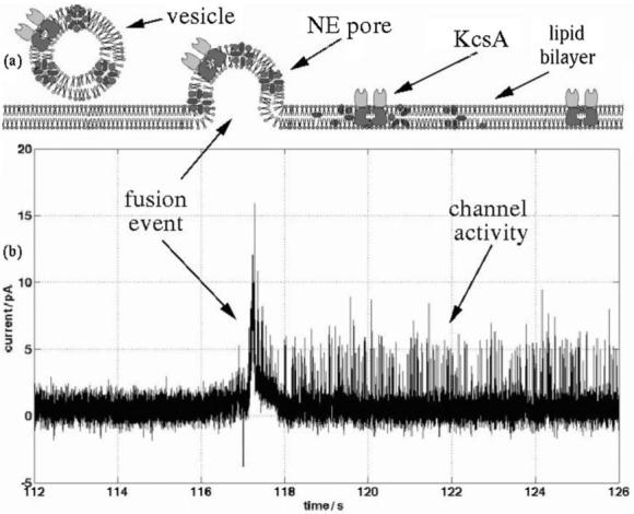
(a) Schematic diagram showing the mechanisms for vesicle fusion with a BLM. The vesicle is loaded with KcsA channels and nystatin–ergosterol pores. After fusion the latter disassemble within a few seconds, whilst the potassium channels remain active. (b) Current trace of a vesicle fusion event, showing channel activity; data obtained using conventional BLM apparatus. The fusion is marked by a large transient current spike, which decays when the nystatin–ergosterol pore disassembles. A 450 mM KCl gradient is present across the BLM (150 mM, pH 4, 10 mM HEPES-600 mM, pH 7.4, 10 mM HEPES), to induce vesicle fusion. A 100 mV voltage potential was maintained throughout the process (the relative polarity has no effect on the fusion process).
KcsA potassium channels do not spontaneously incorporate into a BLM, therefore these proteins were used to demonstrate the generic applicability of the N/E technique for protein delivery into an on-chip BLM.
Bilayer on chip
Chip-based bilayer technologies present a number of challenges compared with conventional bilayer systems. The reduced dimensions (volume decreased from mL to μL), lead to an increase in the surface-to-volume ratio, together with the impracticality of manually manipulating the electrolyte, as is done in a conventional system. However, microfluidics offers advantages, including automatic injection, and exchange or perfusion of buffers and vesicles. The rate of vesicle fusion events is related to the degree of liquid agitation,40,41 which is easier to control in a chip system, compared to conventional apparatus.
Device structure and on-chip BLM formation
Devices for forming BLMs were fabricated from poly(methyl methacrylate) (PMMA) and polytetrafluoroethylene (PTFE) (Fig. 2a) using a combination of hot embossing and solvent bonding techniques, as previously described.42
Fig. 2.
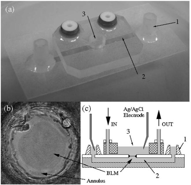
(a) A photograph of a polymeric device used for forming BLMs: 1. fluid inlet and outlet; 2. bottom channel (trans side); 3. top well (cis side). An aperture (100 μm diameter) is laser/mechanically drilled in the PMMA (or PTFE) film (50 μm thickness) in the centre of the well, providing a connection from the lower fluidic channel to the upper well. (b) Optical transmission photograph of a bilayer formed across a PTFE aperture (dark area) surrounded by the annulus (bright area). (c) A cross section of the chip. In the upper half of the device (cis side), two microfluidic channels are used for delivery of liquids and perfusion of buffer (IN and OUT). The bottom channel is always filled with buffer and the ion channel current is recorded through Ag/AgCl electrodes inserted into one of the bottom channel inlets.
The device comprises three layers: a PMMA base layer (125 μm thick), a PMMA or PTFE middle layer (50 μm) that contains the aperture for BLM formation, and a PMMA well as the upper layer (3 mm). The lower channel (which is connected to the top well through the aperture) was fabricated either by hot embossing a PMMA sheet, or by cutting a channel in double-sided adhesive tape, which was subsequently used to bond the bottom and middle layers.
The bilayer membrane (Fig. 2b) was formed using an “air-exposure technique”,43 controlled by on-chip fluidics. The method for forming the bilayer is as follows. After filling the entire device with buffer, the upper well was drained through the connecting channel (OUT in Fig. 2c). The hydrophobic characteristics of the middle layer and the position of the draining channel are such that when the buffer is removed from the top well, the solution in the lower channel remains unchanged.
A small volume (<0.5 μL) of lipid solution (7 : 3 1-palmitoyl-2-oleoyl-sn-glycero-3-phospho-rac-1-glycerol : 1-palmitoyl-2-oleoyl-sn-glycero-3-phosphoethanolamine (POPE : POPG), Avanti Polar Lipids, Alabama, USA) was then pipetted into the well. Following a further injection of buffer (IN, Fig. 2c), the well was again drained and the remaining lipid film left exposed to air for a short period of time (10-40 s). During this period, the lipid film began to thin. As the lower layer of the device was produced from transparent PMMA film, the thinning of the lipid film was observed optically. Once a lipid membrane had formed across the majority of the aperture, the well was re-filled by a final injection of buffer. The BLM capacitance and transmembrane current were monitored during the entire process. This technique has been intensively tested with a yield of approximately 90%.43 Experiments show that flow control is not a critical issue, provided that the middle layer is sufficiently hydrophobic (contact angle >90°) and that the surface is cleaned using solvents prior to the experiments.
Proteoliposome reconstitution
Proteins were reconstituted in N/E vesicles using a modification of a previously reported method.39 This alternative procedure is advantageous for the incorporation of large protein molecules, because steps such as vesicle extrusion, freeze-thawing and sonication, which could damage proteins, are not used.
KcsA with an N-terminal hexahistidine tag was over-expressed and purified as previously described.44 A combination of POPE : POPG : ergosterol, at molar ratios of 6 : 3 : 1 and 5.5 : 3 : 1.5 respectively, were mixed in chloroform, dried, and re-suspended in buffer (10 mM HEPES, 450 mM KCl pH 7.4) containing 40 mM β-d-octyl glucoside to give a final total lipid concentration of 10 mg mL-1. The sample (1-2 mL) was then sonicated to optical clarity in a bath sonicator. KcsA (40 μg) was mixed with the lipid sample to give a 22 000: 1 molar ratio of lipid: KcsA tetramer. Detergent was removed by addition of 80 mg of washed SM2 Bio-Beads (mesh size 20-50, Bio-Rad) followed, after one hour, by a second addition of 80 mg Bio-Beads.45 After a further hour, the sample of reconstituted vesicles (150-350 nm diameter, as estimated from light scattering) was removed from the Bio-Beads and kept on ice until use. Alternatively, proteoliposomes were stored at 4 °C for two weeks without loss of channel functionality. Nystatin (Fluka), diluted in anhydrous methanol (7 μL at 2.5 mg mL-1), was added to an aliquot of the ergosterol-containing proteoliposomes (100 μL) and additional buffer (100 μL of 450 mK KCl, 10 mM HEPES, pH 7.4). The final sample was left to rest for approximately 60 min at 4 °C to allow the nystatin to incorporate into the vesicles, thus forming nystatin–ergosterol channels within the membrane of the proteoliposomes. A schematic diagram of this procedure is shown in Fig. 3. After bilayer formation, protein incorporation was initiated by injecting aliquots of the vesicle solution into the upper well (Fig. 2c).
Fig. 3.
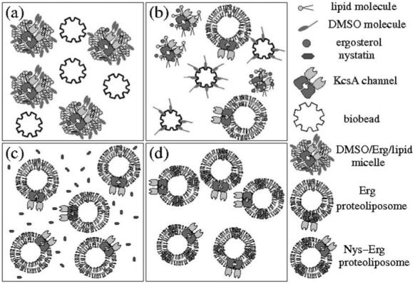
Schematic diagram showing the procedure for protein reconstitution into vesicles. (a) Bio-Beads are mixed with a solution containing lipid-detergent micelles with KcsA channels. (b) Bio-Beads slowly remove the detergent, resulting in the formation of unilamellar vesicles. (c) Nystatin (Nys) is added to a solution of ergosterol (Erg)-containing proteoliposomes. (d) After 1 h, nystatin has inserted spontaneously into the vesicles, forming N/E pores.
Results and discussion
The technique for protein delivery was tested and compared with alternative techniques,35 which were also successfully reproduced within the microfluidic chip. The results are presented below, together with a critical evaluation of the N/E method compared with alternative approaches.
N/E vesicle fusion on chip
After formation of a BLM (using the air exposure method), 6.5 μL of 3 M KCl was injected into the upper well (cis side), creating a salt gradient of 400 mM across the bilayer. Two different populations of vesicles were then tested; the first containing 10% ergosterol (molar ratio) and the second containing 15% ergosterol (molar ratio), each containing KcsA channels. Fig. 4a and b show current data of the fusion for the two different vesicle types. The first (10% ergosterol) is marked by a fast decay (0.1 s) of the current spike, while the second is characterised by a slower (6 s) decay. Because of the difference in ergosterol concentrations in the vesicles, disaggregation of the N/E pores occurs over a longer time in the second case.41 In both cases, single channel activity from the KcsA is observed.
Fig. 4.

(a) Electrical current recording for a fast vesicle fusion event (100 μs), where channel activity is observed immediately after fusion. Liposome composition: 6 : 3 : 1 POPE : POPG : ergosterol (10% ergosterol). (b) Current recording showing vesicle fusion where channel activity is observed during the current decay. Liposome composition: 5.5 : 3 : 1.5 POPE : POPG: ergosterol (15% ergosterol). (c) Single channel activity of KcsA, after insertion into the BLM (150/550 mM KCl, 10 mM HEPES, pH 4/7.4). Applied potential is 75 mV. (d) I-V curve of KcsA in 100 mM KCl, 10 mM HEPES, pH 4/7.4, compared with previously reported data.36 Each data point on the I-V curve is the average of 20 current values for opening events, at each applied potential.
After fusion, the current returns to a stable baseline (0.5-1 pA) with electrical activity characteristic of single channel functionality (Fig 4c). This occurs approximately 80% of the time, typically 1-2 min after a fusion. The buffer solution on the cis side is then perfused with vesicle free low-salt buffer, through the inlet and outlet channels (IN and OUT in Fig. 2c). This action neutralises the salt gradient across the BLM.
This is necessary whenever a salt gradient is present because the imbalance in electrolyte concentration causes an electrochemical potential to develop across the membrane, which is superimposed on the applied voltage.35,36 Buffer exchange also removes the proteoliposomes that remain above the membrane, minimising further fusion events. By monitoring the fusion events, buffer exchange can be initiated when the required number of active channels has been delivered to the BLM.
Fusion events can be increased by agitation of the vesicle suspension in the upper well by removing and re-injecting a few μL of buffer. This has the effect of increasing the probability that vesicles come into contact with the bilayer membrane. Microfluidic agitation of the vesicles is an alternative method to the stirring used in conventional BLM apparatus,39 and provides a controlled method for inducing fusion.
Each 0.5 μL injection of vesicles dispenses approximately 1010 proteoliposomes into the 40 μL volume of the upper well. The vesicle size was measured by dynamic light scattering and SEM (Fig. 5a and b), and was found to be in the range of 150-350 nm in diameter. Therefore, at the protein concentration used in the reconstitution, each vesicle contains on average 5-10 KcsA channels.
Fig. 5.
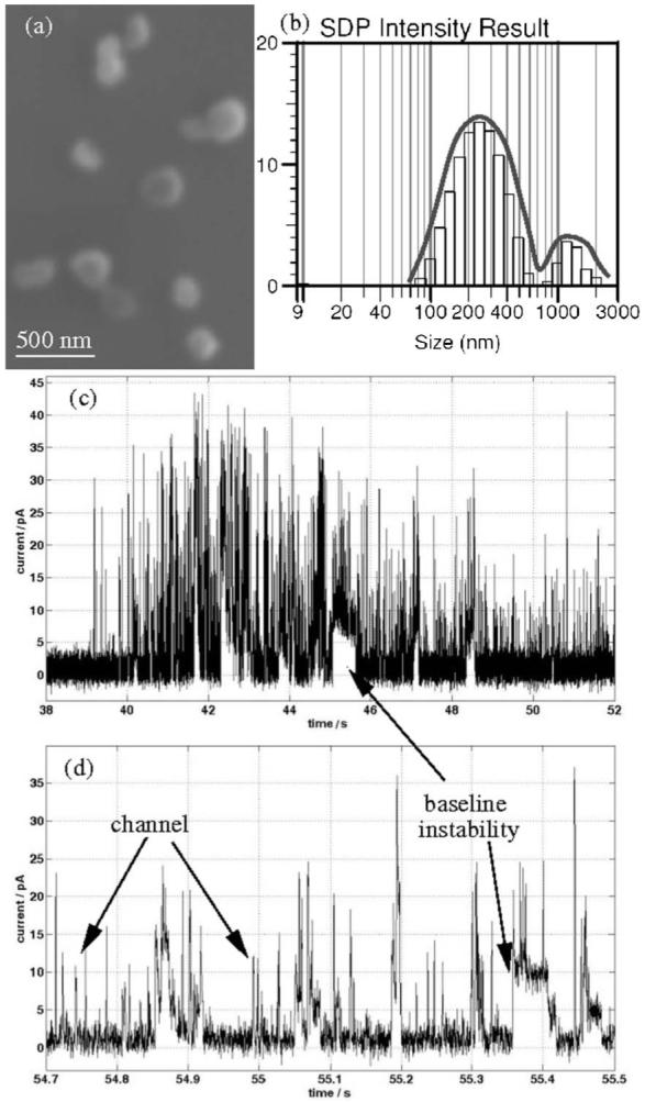
(a) SEM image of single protein-containing vesicles, average size 250 nm. (b) Dynamic light scattering of proteoliposome solution at 90° angle. (c-d) Examples of transmembrane current traces obtained after proteoliposome incorporation, initiated by rupture and reforming of the BLM. Using this method, the current baseline showed abnormal random current spikes, superimposed on KcsA channel activity.
Even though the number of vesicles is high, without continuous stirring the fusion rate is very low (0.1-1 fusion min-1); an extremely small number of vesicles fuse with the bilayer. Although calculations indicate that there are 5-10 KcsA channels per vesicle, at most only 1-2 channel current steps are observed after each fusion. This may mean that the channels are characterised by a very low open state probability or that they are reconstituted within the BLM in a non-functional state. The concentration of protein channels in the vesicles could be optimised to control the number of molecules inserted per fusion event.
The main problem with the N/E technique is vesicle aggregation. The gradual formation of large multilamellar vesicles or large lipid aggregates (small peak in Fig. 5b, in the range of 1-3 μm) results in the loss of fusogenic activity and can cause BLM instability. Sonication or vortexing of the vesicle sample decreases vesicle size39 and aggregation, although not completely. Even so, this method is still reliable and provides a route to chip-based electrophysiology measurements of ion channels. As an example, an I-V curve for the KcsA channel is presented in Fig. 4d, showing correlation with previously reported data27 obtained using a conventional system.
Incorporation of channels into the membrane was also attempted by creating a salt gradient across the BLM using proteoliposomes without N/E. Channel activity was only occasionally obtained; there was no clear evidence of fusion events, nor could the number of fusion events be evaluated, rendering the procedure less robust and unpredictable. The N/E vesicle fusion technique has the potential to be semi-automated, for example using robotic injection of lipids and proteins, perfusion of buffer with automated syringe pumps, etc. This procedure could also be transferable to an array platform.8,43
Alternative on-chip approach
Chip experiments using the “air-exposure” and N/E technique require more complex procedures than a conventional BLM system, but the methods could be automated. As recently demonstrated,43 the air-exposure technique is a reliable method for on-chip BLM formation. The technique has also been used for the simultaneous formation of three separate BLMs on chip.43 The horizontal, transparent, polymeric chip structure allows not only for electrical recording of ion channels and visualisation of the BLM formation, but has the potential for single molecule (fluorescence) imaging, providing a capability for simultaneous optical and electrical measurement of ion channels.
Alternative approaches to protein insertion could be implemented within the chip-based platform. For example, a recently published method involves covering the tip of a micromanipulated probe with a mixture of proteins and agarose.46 This is then inserted into the bilayer membrane, depositing ion-channels.
A widely used technique (on a conventional BLM apparatus) for protein incorporation involves breaking and immediately reforming a BLM in the presence of protoliposomes. Channel insertion occurs because the vesicles in suspension fuse with the BLM during bilayer re-formation.35
This procedure was implemented using our chip. After forming a stable BLM, proteoliposomes were injected and the membrane broken. This was achieved either using the microfluidics or by applying a high voltage, causing electrical breakdown. In the first case, after draining the upper well, the BLM was exposed to air for over one minute, which caused BLM rupture. In approximately 50% of cases, a bilayer could be reformed by removing and re-injecting the buffer using the microfluidics. However, ion-channel activity was not always observed. On average, after reforming the BLM, channel activity was observed 50% of the time. However, this process, as shown in Fig. 5c-d, generally resulted in a baseline current that was not stable. As shown in the figure, occasional jumps were seen in the baseline current, probably due to instability in the BLM. Single channel activity was observed, but the lifetime of the BLM was substantially shortened using this method.
Lifetime and stability
Important characteristics of the system are the lifetime of the channel-containing BLM and the breakdown voltage. This data is summarised in Fig. 6. Two different experiments were carried out. First, after a fusion event and following the observation of channel activity, the bilayer capacitance was monitored until the bilayer current increased leading to eventual rupture of the membrane. Secondly, after channel insertion, the applied potential across the BLM was varied in order to determine the breakdown voltage.
Fig. 6.
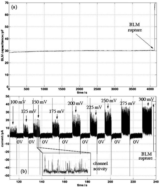
(a) Capacitance trace of a BLM formed on chip showing rupture after 4000 s. (b) Plot of the bilayer current for different voltage steps applied intermittently to a BLM formed on chip containing KcsA channels, in order to determine the membrane breakdown voltage.
Fig. 6a shows a capacitance trace for a protein-containing BLM formed on-chip. As shown, the bilayer was stable for more than 1 h after channel insertion. The time required for BLM formation, vesicle injection, fusion events to occur and stable channel activity to appear was 20-30 min, indicating that a typical BLM lifetime is approximately 1.5-2 h. A bilayer (formed on chip) without protein has a longer lifetime of 3 to 4 h.43
Fig. 6b shows a current plot of a BLM formed on-chip with ion-channels. The applied potential was increased incrementally (from 100 mV) in steps of 25 mV, whilst simultaneously measuring the current. The BLM was generally stable until the applied potential reached 300 mV, typical of the maximum potential applied to bilayers before breakdown. At this voltage, the current jumps due to rupture of the BLM. The figure shows that each time the potential is switched to zero, prior to rupture, the current level returns to a zero baseline value, confirming the stability of the on-chip protein-containing BLM.
Conclusions
We have demonstrated a method for the controlled delivery of the K+ channel KcsA to an artificial lipid bilayer formed in a microfluidic chip. The protein was incorporated into vesicles containing nystatin and ergosterol, which were then fused with the bilayer. The method provides an electrical indication of vesicle fusion. The procedure is shown to be a controllable and reliable method for the delivery of non-spontaneously inserting proteins into bilayers. The proposed protocol has potential for use in developing high sensitivity, single molecule biosensors based on artificial membrane systems and for general electrophysiology experiments. The technique is also amenable to semi-automation and for use in an array platform.
Acknowledgements
This work is supported by the 6th Framework Programme of the European Commission under the contract NMP4-CT-2005-017114 “RECEPTRONICS”, the UK Interdisciplinary Research Centre in Bio-Nanotechnology (R45659/01) and by Wellcome Trust. SEM images were acquired at Biomedical Image Unit, Southampton General Hospital, with the help of Dr Anton Page. Dynamic light scattering were recorded in the laboratory of Prof. G. Attard, School of Chemistry, University of Southampton.
References
- 1.Booth IR, Edwards MD, Miller S. Biochemistry. 2003;42:10045–10053. doi: 10.1021/bi034953w. [DOI] [PubMed] [Google Scholar]
- 2.Kung C, Blount P. Mol. Microbiol. 2004;53:373–380. doi: 10.1111/j.1365-2958.2004.04180.x. [DOI] [PubMed] [Google Scholar]
- 3.Durick K, Negulescu P. Biosens. Bioelectron. 2001;16:587–592. doi: 10.1016/s0956-5663(01)00173-7. [DOI] [PubMed] [Google Scholar]
- 4.Ko HJ, Park TH. Biol. Chem. 2006;387:59–68. doi: 10.1515/BC.2006.009. [DOI] [PubMed] [Google Scholar]
- 5.Tanaka M, Sackmann E. Nature. 2005;437:656–663. doi: 10.1038/nature04164. [DOI] [PubMed] [Google Scholar]
- 6.Benians A, Leaney JL, Milligan G, Tinker A. J. Biol. Chem. 2003;278:1081–10858. doi: 10.1074/jbc.M212299200. [DOI] [PubMed] [Google Scholar]
- 7.Ichikawa T, Aoki T, Takeuchi Y, Yanagida T, Ide T. Langmuir. 2006;22:6302–6307. doi: 10.1021/la0535025. [DOI] [PubMed] [Google Scholar]
- 8.Zagnoni M, Sandison ME, Wood RJ, Roach PL, Morgan H. uTAS, Proceedings of the 10th International Conference on Miniaturized Systems for Chemistry and Life Sciences; Tokyo. 2006.pp. 1342–1344. [Google Scholar]
- 9.Zhang YL, Dunlop J, Dalziel JE. Biosens. Bioelectron. 2007;22:1006–1012. doi: 10.1016/j.bios.2006.04.009. [DOI] [PubMed] [Google Scholar]
- 10.Trojanowicz M. J. Anal. Chem. 2001;371:246–260. doi: 10.1007/s002160101005. [DOI] [PubMed] [Google Scholar]
- 11.Ide T, Takeuchi Y, Yanagida T. Single Mol. 2002;3:33–42. [Google Scholar]
- 12.Terrettaz S, Mayer M, Vogel H. Langmuir. 2003;19:5567–5569. [Google Scholar]
- 13.Atsuta K, Noji H, Takeuchi S. Lab Chip. 2004;4:333–336. doi: 10.1039/b400774c. [DOI] [PubMed] [Google Scholar]
- 14.Fertig N, Klau M, George M, Blick RH, Behrends JC. Appl. Phys. Lett. 2002;81:4865–4867. [Google Scholar]
- 15.Li X, Klemic K, Reed M, Sigworth FJ. Nano Lett. 2006;6:815–819. doi: 10.1021/nl060165r. [DOI] [PubMed] [Google Scholar]
- 16.Pantoja R, Nagarah JM, Starace DM, Melosh NA, Blunck R, Bezanilla F, Heath JR. Biosens. Bioelectron. 2005;20:509–517. doi: 10.1016/j.bios.2004.02.020. [DOI] [PubMed] [Google Scholar]
- 17.Klemic KG, Klemic JF, Reed MA, Sigworth FJ. Biosens. Bioelectron. 2002;17:597–604. doi: 10.1016/s0956-5663(02)00015-5. [DOI] [PubMed] [Google Scholar]
- 18.Tien HT, Ottawa A. J. Membr. Sci. 2001;189:83–117. [Google Scholar]
- 19.Schmitt EK, Vrouenraets M, Steinem C. Biophys. J. 2006;91:2163–2171. doi: 10.1529/biophysj.106.083592. [DOI] [PMC free article] [PubMed] [Google Scholar]
- 20.Suzuki H, Tabata K, Kato-Yamada Y, Noji H, Takeuchi S. Lab Chip. 2004;4:502–505. doi: 10.1039/b405967k. [DOI] [PubMed] [Google Scholar]
- 21.Ide T, Ichikawa T. Biosens. Bioelectron. 2005;21:672–677. doi: 10.1016/j.bios.2004.12.018. [DOI] [PubMed] [Google Scholar]
- 22.Suzuki H, Tabata KV, Noji H, Takeuchi S. Langmuir. 2006;22:1937–1942. doi: 10.1021/la052534p. [DOI] [PubMed] [Google Scholar]
- 23.Malmstadt N, Nash MA, Purnell RF, Schmidt JJ. Nano Lett. 2006;6:1961–1965. doi: 10.1021/nl0611034. [DOI] [PubMed] [Google Scholar]
- 24.Harms GS, Orr G, Montal M, Thrall BD, Colson SD, Lu HP. Biophys. J. 2003;85:1826–1838. doi: 10.1016/S0006-3495(03)74611-6. [DOI] [PMC free article] [PubMed] [Google Scholar]
- 25.Maurer JA, White VE, Dougherty DA, Nadeau JL. Biosens. Bioelectron. 2007;22:2577–2584. doi: 10.1016/j.bios.2006.10.017. [DOI] [PubMed] [Google Scholar]
- 26.Fertig N, Meyer Ch., Blick RH, Trautmann Ch., Behrends JC. Phys. Rev. E. 2001;64:040901. doi: 10.1103/PhysRevE.64.040901. [DOI] [PubMed] [Google Scholar]
- 27.Suzuki H, Tabata KV, Noji H, Takeuchi S. Biosens. Bioelectron. 2007;22:1111–1115. doi: 10.1016/j.bios.2006.04.013. [DOI] [PubMed] [Google Scholar]
- 28.Ingolia TD, Koshland DE. J. Biol. Chem. 1978;253:3821–3829. [PubMed] [Google Scholar]
- 29.Cohen FS, Zimmerberg J, Finkelstein A. J. Gen. Physiol. 1980;75:251–270. doi: 10.1085/jgp.75.3.251. [DOI] [PMC free article] [PubMed] [Google Scholar]
- 30.Cohen F, Akabas MH, Zimmerberg J, Finkelstein A. J. Cell Biol. 1984;98:1054–1062. doi: 10.1083/jcb.98.3.1054. [DOI] [PMC free article] [PubMed] [Google Scholar]
- 31.Finkelstein A, Zimmerberg J, Cohen FS. Annu. Rev. Physiol. 1986;48:163–174. doi: 10.1146/annurev.ph.48.030186.001115. [DOI] [PubMed] [Google Scholar]
- 32.Niles WD, Cohen FS, Filkelstein A. J. Gen. Physiol. 1989;93:211–244. doi: 10.1085/jgp.93.2.211. [DOI] [PMC free article] [PubMed] [Google Scholar]
- 33.Woodburry DJ, Hall JE. Biophys. J. 1988;54:1053–1063. doi: 10.1016/S0006-3495(88)83042-X. [DOI] [PMC free article] [PubMed] [Google Scholar]
- 34.Jiang Y, Lee A, Chen J, Cadene M, Chait BT, MacKinnon R. Nature. 2002;417:515–522. doi: 10.1038/417515a. [DOI] [PubMed] [Google Scholar]
- 35.Heginbotham L, LeMasurier M, Kolmakova-Partensky L, Miller C. J. Gen. Physiol. 1999;114:551–559. doi: 10.1085/jgp.114.4.551. [DOI] [PMC free article] [PubMed] [Google Scholar]
- 36.LeMasurier M, Heginbotham L, Miller C. J. Gen. Physiol. 2001;118:303–313. doi: 10.1085/jgp.118.3.303. [DOI] [PMC free article] [PubMed] [Google Scholar]
- 37.Nimigean CM, Miller C. J. Gen. Physiol. 2002;120:323–335. doi: 10.1085/jgp.20028614. [DOI] [PMC free article] [PubMed] [Google Scholar]
- 38.Woodbury DJ, Miller C. Biophys. J. 1990;58:833–839. doi: 10.1016/S0006-3495(90)82429-2. [DOI] [PMC free article] [PubMed] [Google Scholar]
- 39.Woodbury DJ. Methods Enzymol. 1999;294:319–339. doi: 10.1016/s0076-6879(99)94020-x. [DOI] [PubMed] [Google Scholar]
- 40.Woodbury DJ, Rognlien K. Cell Biol. Int. 2000;24:809–818. doi: 10.1006/cbir.2000.0631. [DOI] [PubMed] [Google Scholar]
- 41.de Planque MRR, Mendes GP, Zagnoni M, Sandison ME, Fisher KH, Berry RM, Watts A, Morgan H. IEE Proc. Nanobiotechnol. 2006;153:21–30. doi: 10.1049/ip-nbt:20050039. [DOI] [PubMed] [Google Scholar]
- 42.Sandison ME, Morgan H. J. Micromech. Microeng. 2005;15:139–144. [Google Scholar]
- 43.Sandison ME, Zagnoni M, Morgan H. Langmuir. 2007 DOI: 10.1021/la7007528. [Google Scholar]
- 44.Marius P, Alvis SJ, East JM, Lee AG. Biophys. J. 2005;89:4081–4089. doi: 10.1529/biophysj.105.070755. [DOI] [PMC free article] [PubMed] [Google Scholar]
- 45.Rigaud J, Levy D, Mosser G, Lambert O. Eur. Biophys. J. 1998;27:305–319. [Google Scholar]
- 46.Holden MA, Bayley H. J. Am. Chem. Soc. 2005;127:6502–6503. doi: 10.1021/ja042470p. [DOI] [PubMed] [Google Scholar]