

Abstract
We describe the design and testing of an inductive coupling system used to power an implantable minipump for applications in ambulating rats. A 2 MHz class-E oscillator driver powered a coil transmitter wound around a 33-cm-diameter rat cage. A receiver coil, a filtered rectifier, and a voltage-sensitive switch powered the implant. The implant DC current at the center of the primary coil (5.1 V) exceeded the level required to activate the solenoid valve in the pump. The variations of the implant current in the volume of the primary coil reflected the variations of the estimated coupling coefficient between the two coils. The pump could be activated in-vivo, while accommodating the vertical and horizontal movements of the animal. Advantages of this design include a weight reduction for the implant, an operation independent from a finite power source, and a remote activation/deactivation.
Index Terms: Infusion pump, implantable device, radio-frequency field, transcutaneous coupling, wireless energy transfer
I. Introduction
In many areas of animal research, administering a pharmacologic agent without the animal’s awareness minimizes handling stress, which affects many biologic variables. We recently developed a self-contained, implantable, microbolus infusion pump (MIP) that allows bolus drug administration by remote activation in small animals [1]. Application of the first generation MIP has been demonstrated in freely moving rats for acute administration of radiotracers during functional neuroimaging paradigms [2], [3]. However, widespread application of this technology has been limited by its dependence on finite primary battery capacity. This communication presents a new design and validation of an MIP powered transcutaneously using an external resonating inductive coil.
II. Methods
A. Overview
The original MIP [1] consisted of four components in series: a pressurized, liquid-filled, elastomeric reservoir (Advanced Neuromodulation Systems, Piano, TX), a coiled ejection chamber containing the pharmacologic agent, an electronics module used to control a miniature solenoid valve, and an intravenous catheter. The solenoid valve (LHDA1202025H, Lee Company, Essex, CT) chosen for its small size (5.3 mm diameter, 21.3 mm length) and weight (2 g) required a nominal 21 mA current pulse at 12 V to open, which was provided by four 3 V lithium batteries in series. Thereafter, a minimal 2.4 mA DC current (Ivalve,min) at 3.7 V sufficed to keep the valve open. In the new MIP controller, a small inductive coil coupled to a larger primary coil placed around the animal’s cage replaces the batteries.
B. Primary Transmitter
The combination of a class-E tuned power oscillator and an inductive link has been broadly described [4]–[6]. Here, the primary coil (Lp ~ 12 μH, Qp = 160) was made of 5 turns of 10-gage electric cable (total length 550 cm) spiral-wound from 5 cm to 13 cm above the floor of a cylindrical plastic rat cage (radius rcage = 16.5 cm). Such an arrangement placed the secondary coil implanted on the back of an adult rat at the mid-height of the primary coil, where the induced field is most intense. The capacitor in the transmitter circuit (Cp ~ 510 pF) was selected to achieve resonance at 2 MHz. The primary coil was driven by a phase-locked class-E oscillator driver in which a 2 MHz reference crystal oscillator prevented frequency fluctuations and de-tuning of the transmitter [7]. The peak-to-peak AC voltage and current in the primary coil were approximately 260 V and 1.7 A, respectively. The primary coil driver drew 0.6 A from a 12 V DC supply, which indicated that the emitted radio-frequency power was at most 7.2 W.
C. Implant Receiver
The receiver coil (Lr= 11.5 μH, Qr = 80) was made of 14 turns of 12-strand, 41-gage Litz wire (Wire Tronic Inc., Pine Grove, CA) wound in a rectangular shape (38 mm × 18 mm) to maintain the size of the pump compatible with implantation in a 350–400 g rat (Fig. 1). The coil and capacitor Cr (~550 pF) formed a parallel resonant circuit at 2 MHz. The induced current was rectified and filtered with a diode bridge made of two pairs of high-speed Schottky diodes (D1—D4) and a filter capacitor (Cf). Preliminary tests showed that, with a 560 Ω resistive load equivalent to the resistance of the solenoid valve (Rv), the DC voltage (5 V) and current (5 mA) were insufficient to activate the valve. For this reason, the receiver circuit included a voltage sensitive switch made of a 12 V Zener diode and a silicon-controlled rectifier (SCR). When the voltage across capacitor Cf reached the breakdown voltage of the Zener diode, the Zener current activated the gate of the SCR to turn it on. The transient current supplied by capacitor Cf opened the valve. The value of Cf (33 μF) was such that the time constant (18 ms) of the capacitor discharge through resistance Rv far exceeded the minimum duration (~ 1 ms) of the current transient required to turn on the valve. After this transient had died out, the tuned coil receiver produced more than the minimal DC current and voltage required to keep the valve open. The red emission of an LED in series with the valve was visible through the skin of the animal to confirm that the valve had opened. The circuit was assembled on a printed circuit board with surface mount components and it was turned off by powering down the external coil driver.
Fig. 1.
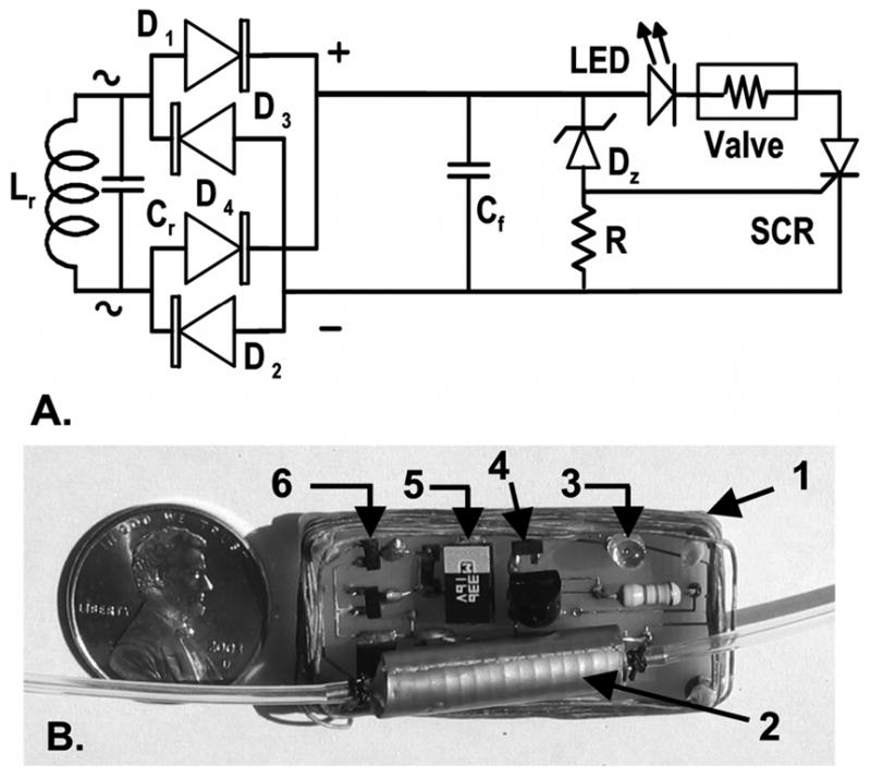
(A) Implant receiver circuit (Lr: secondary coil; Cr: tuning capacitor, D1–D4 dual common anode BAS7006TA and dual common cathode BAS7005TA Schottky diodes, ZETEX Inc., U.K.; Cf: 33 μF filter capacitor; DZ: 12 V Zener diode; R: 47 kΩ resistor; SCR: MCR100–6R, On Semiconductor, China.) (B) Printed circuit prior to silicone embedding. (1: secondary coil, 2: solenoid valve, 3: LED, 4: Zener diode, 5: filter capacitor, 6: diode bridge. Tuning capacitor is below the solenoid valve.).
D. Ex-vivo Characterization
The DC valve current (Ivalve) was measured on a grid (2-cm increment) at altitude (h) = 0 cm, 5.5 cm and 10 cm above the mid-height of the primary coil (corresponding to 9.0, 14.5, and 19.0 cm above the cage floor). Taking into account the cylindrical symmetry of primary coil RF field, current Ivalve was represented as a function of the radial distance (r) from the center of the primary coil to study the effect of lateral movements of the animal within the cross-sectional area of the cage. Using the approach of Zierfoher and Hochmaier [8], the experimental results were validated by computing the coupling coefficient (k) between the two coils for the positions of the secondary coil within the primary coil volume that were tested empirically. In the calculations, the primary coil consisted of five single circular loops 2 cm apart from each other (8 cm total height, 16.5-cm radius) and the secondary coil was represented as a circular coil with the same cross-sectional area as the physical rectangular coil of the MIP. The secondary coil wire had the same overall cross-section as the 12 strand Litz wire used in the physical coil. Other dimensions were identical to those found in the physical model.
To simulate positional changes observed in an animal switching from a quadrupedal to a bipedal posture (rearing), current Ivalve was measured for angles of misalignments between the coil axes (angle α) = 0°, 22.5°, 45°, and 67.5°. These measurements were taken at altitude h = 0 cm, 5.5 cm and 10 cm for radial distances r = 0 cm and r = 12 cm.
E. In-vivo Testing
The circuitry was embedded in a two-part, platinum-cured, room temperature vulcanization (RTV) silicone rubber (VST1556, Factor II, Lakeside, AZ) and connected to the hydraulic components of the MIP as previously described [1]. Functionality of the implant was tested in two rats after 3 weeks of implantation by repeatedly triggering the LED and valve while the animal freely ambulated in its cage.
III. Results
A. Ex-Vivo Tests
In the center of the primary coil (radial distance r = 0, altitude h = 0) and with parallel coil axes (angle α = 0°), current Ivalve was 5.1 mA, well above the minimum current Ivalve,min (2.4 mA) required to keep open the solenoid valve. Current Ivalve increased gradually with r (Fig. 2), reaching 1.8 times the center value near the cage wall (r/rcage = 0.9). The experimental variations of the valve current closely reflected the theoretical variations of the coupling coefficient k between the two coils, suggesting that the variations of current Ivalve reflected changes in energy coupling between the coils. Raising the receiver coil to h = 5.5 and 10 cm reduced Ivalve to 4.4 mA and 3.3 mA, respectively, at the coil center (r = 0). The relationship between Ivalve and r changed from Ivalve increasing with increasing r at altitude h = 0 to Ivalve decreasing with increasing r at altitude h = 10 cm. These variations matched the changes of coupling coefficient k relative to the value of k calculated for r = 0, h = 0.
Fig. 2.

DC valve current (symbols) and coupling coefficient between coils (lines) as a function of radial distance (r) for three altitudes (h = 0, 5.5, 10 cm) of the secondary circuit relative to the mid-height of the primary coil. Radial distance r is expressed as a fraction of the primary coil radius (16.5 cm). Valve current is expressed as a fraction of the current (5.1mA) measured at the center (r = 0 cm) and the mid-height (h = 0 cm) of the primary coil. Relative coupling coefficient is expressed as a fraction of the coupling coefficient (0.02) calculated for r = h = 0 cm.
Increasing the angle α between the coil axes reduced the current in the implant for all radial distances r and altitudes h (Fig. 3). Both in the center (r/rcage = 0) and at the periphery (r/rcage = 0.75) of the primary coil, current Ivalve remained above the minimum current Ivalve,min for α <= 45°. However, the valve current dipped below Ivalve,min for the most extreme angles and altitudes tested.
Fig. 3.

DC valve current (symbols) as a function of angle (α) between the axes of the primary and secondary coils for three altitudes (h = 0, 5.5, 10 cm) of the secondary circuit relative to the mid-height of the primary coil at its center (r = 0) and its periphery (r = 12 cm). For h = 10 cm, the secondary current was insufficient to maintain conduction in the SCR when α was ≥ 22.5° such that the valve current was 0.
B. In-Vivo Tests
Powering the primary coil emitter was immediately followed by the LED becoming brightly lit under the animal skin, demonstrating that the implanted circuitry was producing sufficient current to trigger the valve. The animal’s movement in the cage (ambulation, lying down) maintained the implant within h = ±5 cm of the primary coil mid-height where it could be activated for all positions within the cross-section of the cage. When the animal reared, the implant was raised up to h = 8 cm and it could be operated for angular misalignments ≤ 45°.
IV. Discussion
This study demonstrated that an inductive link can power a miniature infusion pump implanted in freely-moving rats. The primary transmitter coil was sufficiently large to allow for ambulation of the animals and would be suitable for use of the pump in a variety of experimental paradigms [2], [3].
In the midplane of the primary coil, the induced current increased as the implant coil was displaced along the coil radius from the center to the periphery where the density of radio-frequency field lines was highest [6]. The opposite was observed when the implant was raised above the upper rim of the primary coil. Such trends closely matched the calculated variations of the coupling coefficient between coils, suggesting that such calculations [8] could be used to make predictions relative to changes of the coils geometries and dimensions. The induced field in the secondary coil is proportional to the field density and to the cosine of the angle formed by the axes of the primary and secondary coils. Thus, the induced voltage diminished when the secondary coil was tilted relative to the primary coil axis [6]. The progressive current drop with increasing angular misalignment increased when the secondary coil was placed at the periphery of the cage compared to its center and it further accentuated when the secondary coil was raised above the center plane of the primary coil. Misalignment between the coil axes is typically seen during rearing behavior. In our observations, rearing against the wall of the cage occurred infrequently, particularly after the animal was habituated to the cage environment. Misalignments exceeding 45° were brief, due to the rapidity of the animal’ s movement, delaying the triggering of the implant by a few seconds at most.
The efficiency of power transfer between the primary emitter (<7.2 W) and the secondary receiver (26 mW-73 mW) was ≤ 1%, which is low and typical of air-cored coils [9]. Generation of sufficient power to energize the implant could expose the preparation to intense radio-frequency fields leading to internal heating [10], [11]. Absorption of radio-frequency energy in tissue is most intense when the tissue is half the size of the incident wavelength [10]. Minimal absorption was likely in our 2 MHz system because the wavelength (150 m) was much larger than the rat preparation (~ 0.3 mL × 0.1 mW). In-vitro tests conducted on a tissue phantom (200 g chicken breast) showed no temperature change during 60 min exposure in the primary coil. Concurrently a water beaker (300 g water) containing an MIP pump saw its temperature rise by < 0.5°C over the same duration.
Elimination of the batteries in the new generation MIP pump resulted in a ~25% decrease in weight of the implant (32 g to 24 g), while making the implant independent of finite battery capacity. Turning the implant on and off could be achieved without use of a photodetector in the controller circuit [1], allowing the implant to be used in a variety of lighting conditions without risk of inadvertent triggering. The primary coil in the current application was suitable in size for experimentation in an animal the size of the rat. However, many animal paradigms relevant to behavioral pharmacology, and functional neuroimaging occur outside of the animal’s cage environment, and require a larger space for the animal to move about. In such applications inductive power transfer in the home cage could be used to charge a rechargeable battery, which would power the implant outside of the primary coil. Work is ongoing to incorporate rechargeable batteries into the current MIP design.
Acknowledgments
The authors thank Dr. J. Yang, T.R. Sadler, N. Agarwal, and U. Chandrashekar for their help during the experiments.
This work was supported in part the NIBB und er Grant 1 RO1 NS050171 and in part by theWhitaker Foundation under Grant RG-99-0331.
Contributor Information
William H. Moore, Alfred E. Mann Institute, University of Southern California, Los Angeles, CA 90089 USA.
Daniel P. Holschneider, Departments of Psychiatry, Neurology, Cell and Neurobiology, and Biomedical Engineering, University of Southern California, Los Angeles, CA 90089 USA, and the Greater Los Angeles VA Medical Center, Los Angeles, CA 90073 USA (e-mail: Holschne@usc.edu).
Tina K. Givrad, Department of Biomedical Engineering, University of Southern California, Los Angeles, CA 90089 USA.
Jean-Michel I. Maarek, Department of Biomedical Engineering, University of Southern California, Los Angeles, CA 90089 USA (e-mail: maarek@usc.edu).
References
- 1.Holschneider DP, Maarek JM, Harimoto J, Yang J, Scremin OU. An implantable bolus infusion pump for use in freely moving, nontethered rats. Am J Physiol Heart Circ Physiol. 2002;283:H1713–H1719. doi: 10.1152/ajpheart.00362.2002. [DOI] [PMC free article] [PubMed] [Google Scholar]
- 2.Holschneider DP, Maarek JM, Harimoto J, Yang J, Scremin OU. Functional brain mapping in freely moving rats during treadmill walking. J Cereb Blood Flow Metab. 2003;23:925–932. doi: 10.1097/01.WCB.0000072797.66873.6A. [DOI] [PMC free article] [PubMed] [Google Scholar]
- 3.Holschneider DP, Maarek JM, Harimoto J, Yang J, Scremin OU. Activation of cerebral cortex during acoustic challenge or acute foot-shock in freely moving, nontethered rats. Neurosci Lett. 2004;354:74–78. doi: 10.1016/j.neulet.2003.09.078. [DOI] [PMC free article] [PubMed] [Google Scholar]
- 4.Sokal NO, Sokal AD. Class E-A new class of high-efficiency tuned single-ended switching power amplifiers. IEEE J Solid-State Circuits. 1975;SSC-10:168–176. [Google Scholar]
- 5.Zierhofer CM, Hochmair ES. High-efficiency coupling-insensitive transcutaneous power and data transmission via an inductive link. IEEE Trans Biomed Eng. 1990 Jul;37(7):716–722. doi: 10.1109/10.55682. [DOI] [PubMed] [Google Scholar]
- 6.Suaning GJ, Lovell NH. CMOS neurostimulation ASIC with 100 channels, scaleable output, and bidirectional radio-frequency telemetry. IEEE Trans Biomed Eng. 2001 Feb;48(2):248–260. doi: 10.1109/10.909646. [DOI] [PubMed] [Google Scholar]
- 7.Moore WH. United States Patent. Alfred E. Mann Inst. Biomed. Eng., Univ; Southern California: 2005. Switched Reactance Modulated E-Class Oscillator Design. [Google Scholar]
- 8.Zierhofer CM, Hochmair ES. Geometric approach for coupling enhancement of magnetically coupled coils. IEEE Trans Biomed Eng. 1996 Jul;43(7):708–714. doi: 10.1109/10.503178. [DOI] [PubMed] [Google Scholar]
- 9.de N, Donaldson N, Perkins TA. Analysis of resonant coupled coils in the design of radio frequency transcutaneous links. Med Biol Eng Comput. 1983;21:612–627. doi: 10.1007/BF02442388. [DOI] [PubMed] [Google Scholar]
- 10.Shellock FG. Radiofrequency energy-induced heating during MR procedures: a review. J Magn Reson Imag. 2000;12:30–36. doi: 10.1002/1522-2586(200007)12:1<30::aid-jmri4>3.0.co;2-s. [DOI] [PubMed] [Google Scholar]
- 11.Dimbilow PJ. FDTD calculations of the whole-body averaged SAR in an anatomically realistic voxel model of the human body from 1 MHz to 1 GHz. Phys Med Biol. 1997;42:479–490. doi: 10.1088/0031-9155/42/3/003. [DOI] [PubMed] [Google Scholar]