

Abstract
Objectives
To demonstrate the effectiveness of in vivo replicas of fractured ceramic surfaces for descriptive fractography as applied to the analysis of clinical failures.
Methods
The fracture surface topography of partially failed veneering ceramic of a Procera Alumina molar and an In Ceram Zirconia premolar were examined utilizing gold-coated epoxy poured replicas viewed using scanning electron microscopy. The replicas were inspected for fractographic features such as hackle, wake hackle, twist hackle, compression curl and arrest lines for determination of the direction of crack propagation and location of the origin.
Results
For both veneering ceramics, replicas provided an excellent reproduction of the fractured surfaces. Fine details including all characteristic fracture features produced by the interaction of the advancing crack with the material's microstructure could be recognized. The observed features are indicators of the local direction of crack propagation and were used to trace the crack's progression back to its initial starting zone (the origin). Drawbacks of replicas such as artifacts (air bubbles) or imperfections resulting from inadequate epoxy pouring were noted but not critical for the overall analysis of the fractured surfaces.
Significance
The replica technique proved to be easy to use and allowed an excellent reproduction of failed ceramic surfaces. It should be applied before attempting to remove any failed part remaining in situ as the fracture surface may be damaged during this procedure. These two case studies are intended as an introduction for the clinical researcher in using qualitative (descriptive) fractography as a tool for understanding fracture processes in brittle restorative materials and, secondarily, to draw conclusions as to possible design inadequacies in failed restorations.
Keywords: Fractography, ceramic, failure analysis, replica
Introduction
All-ceramic restorations are being increasingly used on posterior teeth– a zone in which the restorations are subjected to higher masticatory loads than on front teeth. Consequently, an increased frequency of veneer ceramic chipping or through-the-core-thickness fractures of posterior crowns may be expected. While a small veneer chipped crown may often be salvaged, larger chips (i.e. interproximal contact loss, cusp fracture) or through-the-core-thickness factures generally result in the complete removal of the failed restoration. Understanding the reasons for such events is of key importance to the dental community as many parameters may be involved such as structure design, choice of ceramic, quality of the final laboratory delivered restoration (i.e. presence of internal defects, damages, residual stresses), and patient specific occlusal contacts and chewing excursion paths. To this end, the analysis of clinical failures using fractographic techniques is gaining momentum in the dental scientific community. The number of related publications, however, is still low [1-7]. The reason pertains to the difficulty in securing pertinent evidence. In particular, it is of importance that the fractured surface of the ceramic part be left undisturbed after failure occurred, that is, that no subsequent grinding, scratching, rubbing or smearing (which in effect “erases” the surface features left during the fracture process) has occurred. Further, while interpreting fractured surfaces from glassy materials is fairly straightforward, recognizing clear surface markings on some of the more coarse-grained or polycrystalline ceramics, may become an intricate procedure [5,8].
Often direct examination of fracture surface under the microscope is not possible because one part of the restoration is still strongly cemented onto its abutment while the other was lost. In these instances a replica of the remaining fracture surface must be obtained. To this end an intra-oral impression of the exposed fractured surface using a low viscosity impression material is taken. The impression (i.e. the negative of the fractured surface) is poured with cold mounting epoxy resin thus producing a positive of the fractured surface which is then gold-sputtered for SEM analysis. Some aspects of the replica technique and the fractographic analysis have been previously published [7]. The objectives of the present report are 1) to detail the steps involved in producing a replica from a fractured surface and 2) using replicas of two clinical fracture sites of all-ceramic restorations to demonstrate the essentials of fractographic analysis.
Materals and Methods
Fracture sites
Two sites were identified for study: 1) A failure of the veneering ceramic of a Procera AllCeram restoration (Nobel Biocare, Gothenburg, Sweden) located on a first upper molar. This restoration has been in function for 4.2 years. 2) A fracture of the veneering ceramic (Allux, Wieland Dental, Pforzheim, Germany) sintered onto an In-Ceram Zirconia core (Vita Zahnfabrik, Bad Säckingen, Germany). This restoration was screw-fastened onto an implant replacing a first upper premolar and failed after 2 months of function.
Replica preparation
The fracture surface (Fig.1) was first cleaned with a cotton pellet and alcohol and was then rinsed and thoroughly air-dried. The replicas were produced using a quadrafunctional hydrophilic siloxane impression material (Aquasil ULV, Dentsply De Trey, Konstanz, Germany) whereby the material was syringed onto the fractured surface (Fig.2) and over the occlusal surface of the crown (Fig.3) without the use of a tray. Subsequently the impressions were poured with cold mounting epoxy resin (Epofix Resin, Struers, Ballerup, Denmark) (Fig.4). After setting, the resin was gold-coated for scanning electron microscopy (SEM).
Fig. 1.
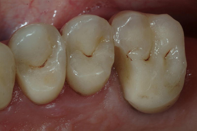
Fracture of the veneering porcelain (AllCeram) of an upper left Procera alumina molar after 4.2 years of intra-oral function
Fig. 2.
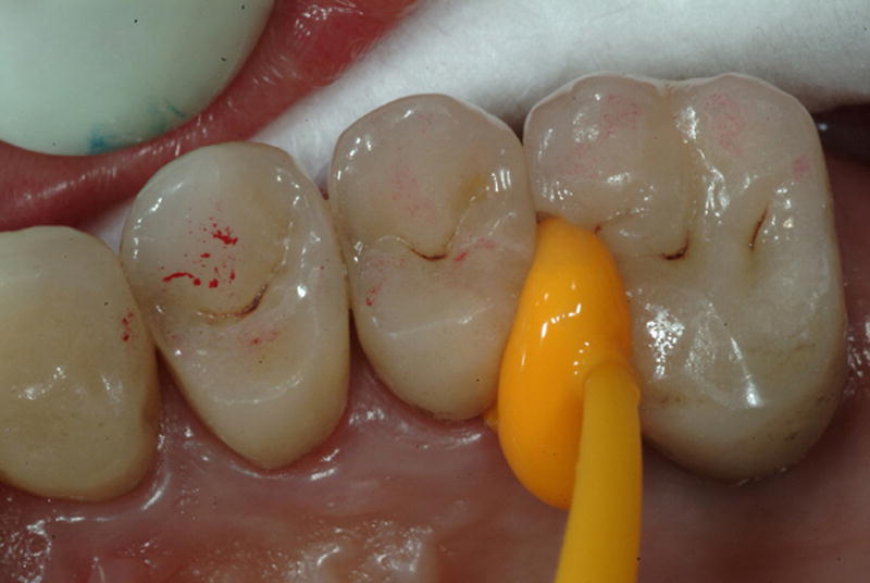
After having cleaned the fractured surface with an alcohol cotton pellet and air-dried, the silicone impression material is injected first on the fractured zone.
Fig. 3.
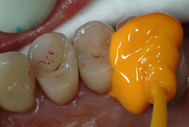
The silicone impression material continues to be injected over the occlusal surface
Fig. 4.
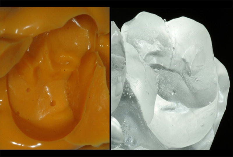
a,b: The impression is poured with epoxy resin reproducing the fractured crown.
Analysis
The description and interpretation of the fracture patterns were based on textbooks descriptions [8-11] and ASTM standard [12]. The main fractographic features searched for were arrest lines, hackle, wake hackle and compression curl [5,7]. An arrest line is a well-defined line produced when the crack comes to a halt, before resuming its propagation, often in a slightly different direction [9]. Arrest lines are also indicators of the direction of propagation as the beginning of a crack event is always located on the concave side of the first arrest line. Hackle are lines on the fracture surface that run in the local direction of cracking. They separating parallel portions of the propagating crack that are on slightly different planes. Hackle lines are commonly formed when the crack moves rapidly [9]. Wake hackle is a trail (wake) emanating from a pore (or other irregularity) and is created by the crack front advancing along the sides of the pore before continuing on slightly different planes [9]. Thus, wake hackle are indicators of the direction of crack propagation. The compression curl is the curved lip just before total fracture of a body loaded in bending.
Results
Failure site 1: Procera AllCeram molar veneer
The resin replica (Fig.4) of the failed Procera AllCeram crown was sputter-coated with gold and inspected under SEM magnification. Figure 5a shows the crown from an occlusal view at low power (10x). Major erosive wear is apparent on all four cusps, usually a sign of abnormal parafunction habits (bruxism). The zone delineated by the frame looks similar to the compression curl often seen in bend bars. Such curved surfaces generally arise from mixed mode loading (tension, shear, torsion), and are found to be typical of final crack break-through in dental crowns. Higher magnifications within the frame (Figs.5b,c) near the interproximal mesial margin show hackle and wake hackle indicating the direction of crack propagation towards the margin.
Fig. 5.
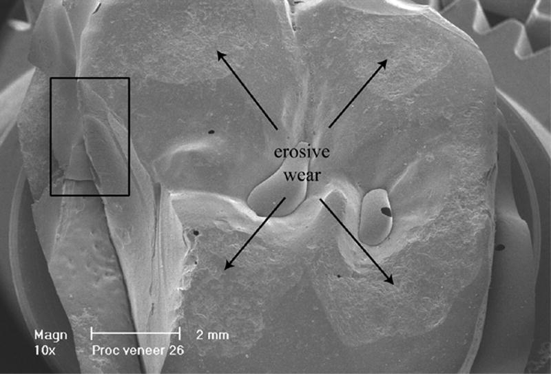

a: Occlusal view (at 10x) of the Procera AllCeram crown showing the veneer failure on the palatal-mesial cusp. Major wear is visible on all four cusps. The frame near the mesial gingival margin is magnified in Fig.5b and Fig.5c
b and c: Higher magnifications within the frame (Fig.5a) near the interproximal mesial margin show hackle and wake hackle indicating the direction of crack propagation towards the margin.
On the fractured surface viewed at 15x magnification (Fig.6) several major arrest lines are observable. The occlusal edge of the palatal cusp (circle) is shown under higher magnification in Figs.7 and 8. On the edge of the fractured surface (large frame in Fig.7) an area of erosive wear spanning about one millimeter is delimited by concave arrest lines. At 127x magnification (Fig.8), this area comprises two deeper damage zones shaped as indents (craters) about 300 μm in diameter followed by arrest lines further downwards. These craters are identified as the origins of the fracture process.
Fig. 6.
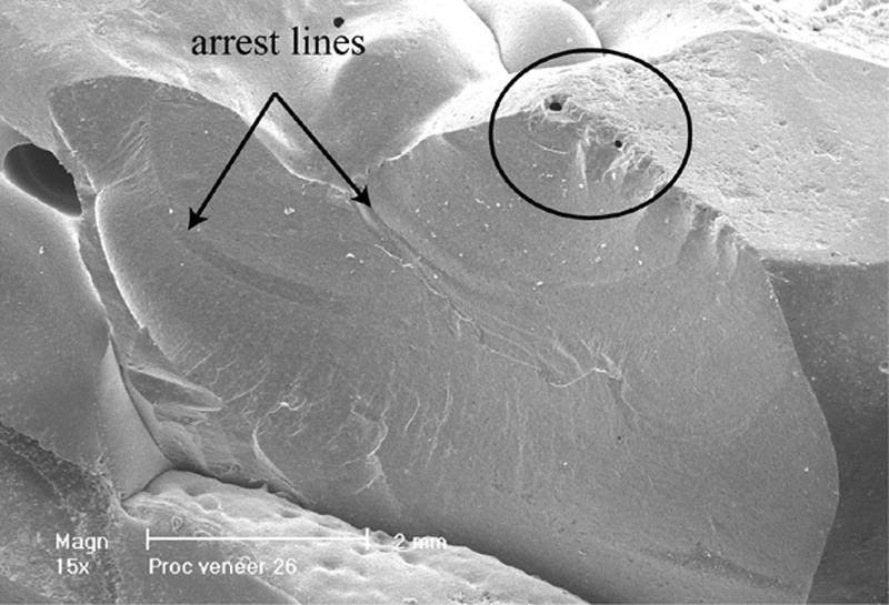
Side view of the Procera AllCeram crown (at 15x). Major arrest lines are recognizable as well as hackle lines. The circled occlusal broken edge shows some surface damage.
Fig. 7.
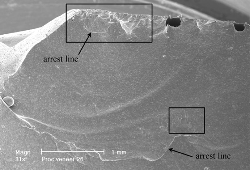
Higher magnification (31x) of the circled area in Fig.6. Several arrest lines are visible (concave well delimited lines). Areas of interest (frames) are scrutinized at higher magnifications in the following figures.
Fig. 8.
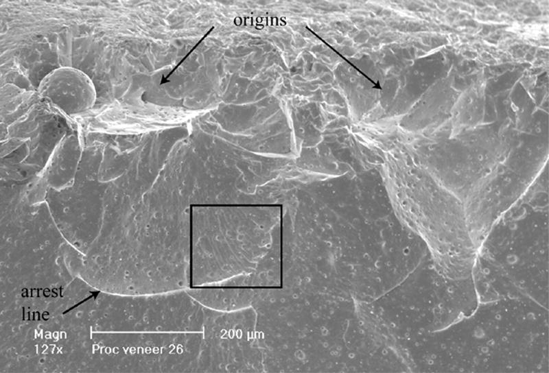
Detailed view (127x) of the occlusal damaged edge (larger frame in Fig.7). Two indented (crater type) areas are identified as the origin sites from which failure started followed by an arrest line. The area near the arrest line delimited by a frame is blown-up in Fig. 9.
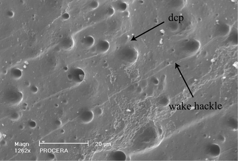
Figure 9 is a further magnification (1029x) of the frame delimited area next to an arrest line in Fig.8 and shows numerous wake hackle emanating from porosities within the veneering ceramic (AllCeram). The trailing character of these lines indicates that the crack front was running from top left to bottom right at this specific site, that is, occlusoapically towards the gingival margin of the crown. Figure 10 is a higher magnification (252x) of the area within the smaller frame in Fig. 7. Here also a number of wake hackle indicate the direction of fracture propagation (top to bottom). Figure 11 is an occlusal view at 31x magnification of the fracture origin demonstrating its location within an occlusal wear facet. Also visible on this figure are three holes (i.e. the black spots) where the epoxy resin did not adequately wet the impression during pouring of the replica. Finally, Fig.12 is a synopsis of the failure process. The origin of the fracture is circled on the palatal cusp. The general direction of crack propagation is marked by the arrows pointing towards the crown margin.
Fig. 9.
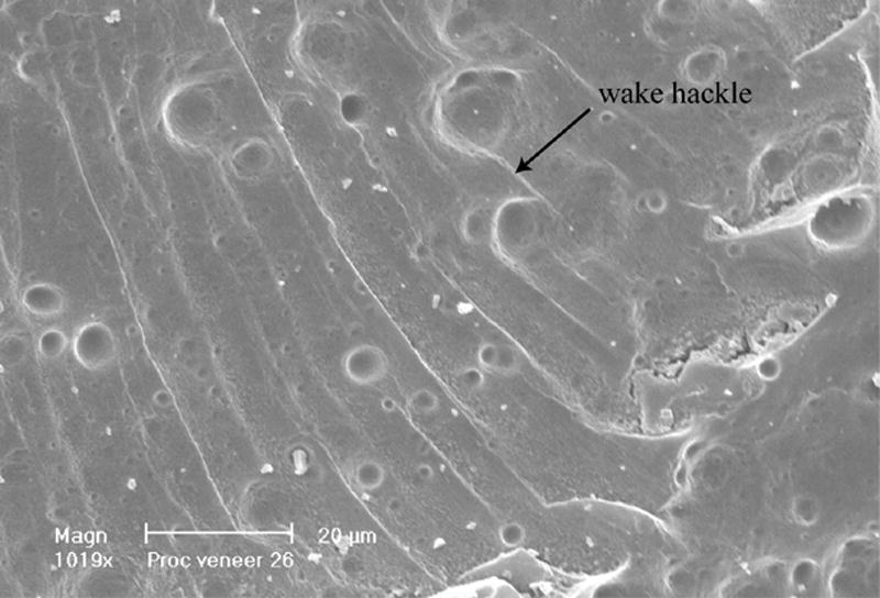
High magnification at 1019x of the frame in Fig.8. Many wake hackle are visible starting from pores within the Procera veneering porcelain (AllCeram). The direction of propagation goes from top to bottom along the trail of the wake hackle.
Fig. 10.
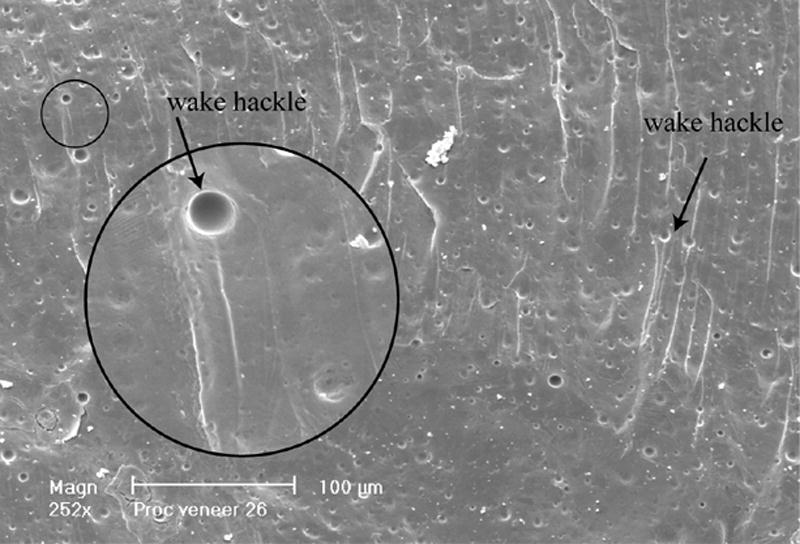
Higher magnification of the smaller frame area in Fig. 7. Wake hackle are clearly recognizable indicating the direction of crack propagation (from top to bottom i.e. from occlusal surface to gingival margins).
Fig. 11.
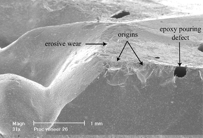
Additional occlusal view at an angle and low magnification (31x) of the crack initiation sites (origins). Note the occlusal worn ceramic surface and resin pouring artifacts (black spots) resulting from poor resin wetting at sharp angles of the replica impression.
Fig. 12.
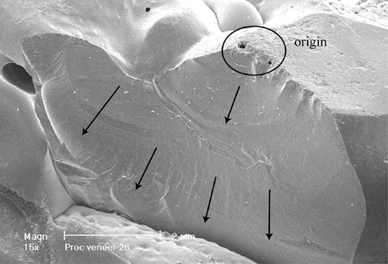
Summary image with circled area for crack initiation and arrows indicating the general direction of crack propagation.
Failure site 2: In-Ceram Zirconia premolar veneer failure
Visual observation of the gold-coated replica (Fig. 13) of the fractured In-Ceram Zirconia upper premolar crown indicates a major chip of the veneering ceramic on the buccal side. Numerous hackle lines curling off towards the gingival margins as well as several smaller ceramic chips on the cusp tip are observable. Fig. 14 (18x) shows a worn cusp tip with several small ceramic chips delimited by concave arrest lines on the buccal surface. The higher magnification on the right of the picture shows several wake hackle emanating from existing pores. Figure 15 is a close up view of the frame in Fig.14 showing a 97x magnification of the worn and damaged cusp tip with arrest- and hackle lines. A comprehensive view of the direction of crack propagation and multiple origins (arrows on cusp tip) is given in Fig. 16.
Fig. 13.
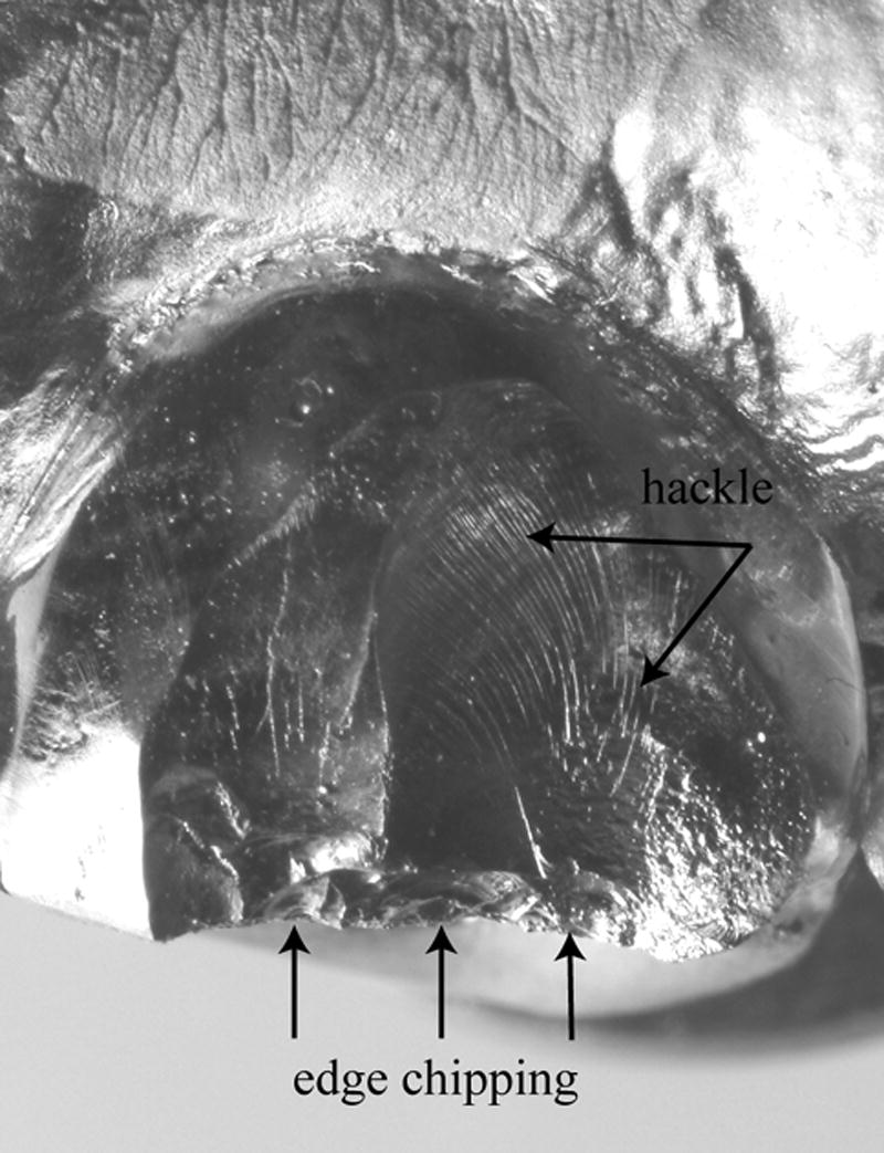
Gold-coated replica of an In-Ceram Zirconia veneering porcelain fracture of an upper first premolar. The naked eye recognizes many hackle lines and a damaged buccal edge with several smaller edge chips.
Fig. 14.
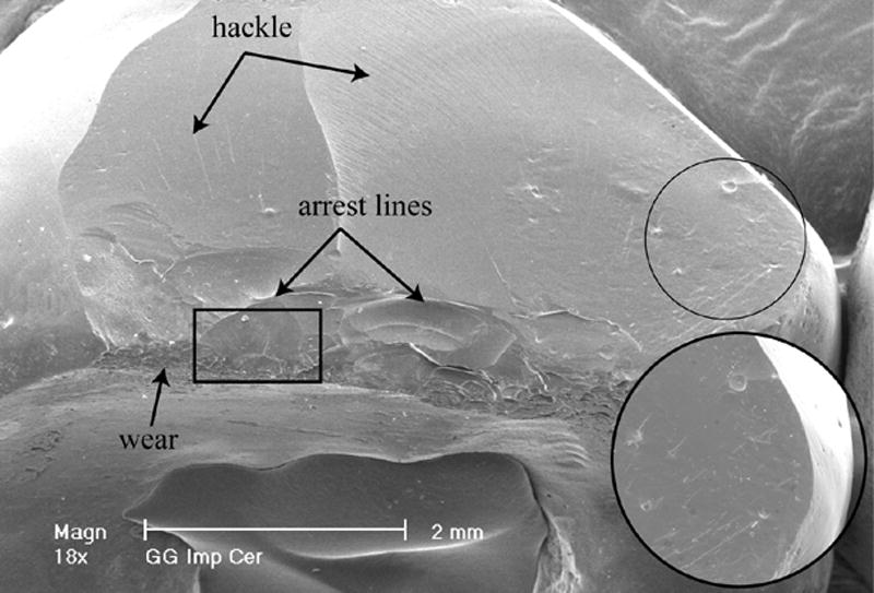
The SEM view at 18x shows evidence of ceramic wear near the fractured edge, arrest lines, hackle and wake hackle (zoom within the image). The frame area is analyzed in Fig. 15.
Fig. 15.
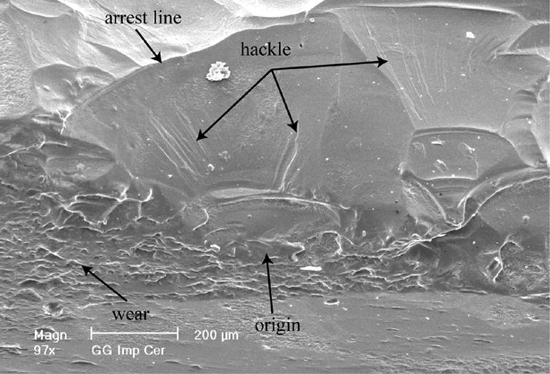
Higher magnification (97x) of the frame delimited occlusal edge area in Fig. 14 showing many arrest lines, hackle, wear and one of several origins on that edge.
Fig. 16.
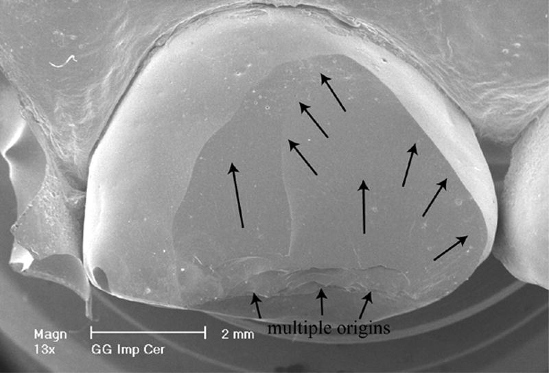
Summary of the failure event with the initiation site on the occlusal buccal edge (cusp tip) and the crack front moving along the arrowed path towards the gingival margins.
Discussion
Replicas are an invaluable aid when bridging the gap between clinical requirements and scientific needs for understanding failure. First, the patient who has suffered the fracture of a ceramic restoration is usually unable to provide the broken fragment, hence this part is not available for study. Second, it is nearly impossible to retrieve the remainder of the failed restoration without damage to the fracture surface as these crowns are strongly cemented to the tooth structure. Third, the patient's functional and esthetic demands require immediate attention which implies that the fracture surface will be altered either by bonding of a composite material or during the removal of the restoration. For all these reasons, replicas have been successfully used by the authors and presented in a previous study on descriptive fractography [7]. In describing the steps of replica production, our goal was to familiarize the clinician with a simple method that provides considerable information to the materials scientist in understanding the fracture process during crown breakage. The reproduction of surface details is excellent providing that the fractured surface is clean and that the injected hydrophilic siloxane impression material adequately wets the fractured surface. To this end, the surface must be devoid of plaque and debris before the impression is taken using a cotton pellet sucked in alcohol for gently rubbing the surface and abundant water and air spray.
In both examples presented in this report, all characteristic features such as hackle, wake hackle and arrest lines were perfectly recognizable in the replica. Hence the fracture process could be explained with respect to the crack's origin and propagation.
In the first case, (Procera AllCeram) the veneering ceramic failed after approximately four years of intraoral function. It could be inferred from the worn occlusal surface pictured on the SEM that this patient had strong bruxing habits (that means a highly stressed crown). It appears that the fairly thick layer of unsupported veneering ceramic (2-3mm) combined to the repetitive loadings generated while the patient was bruxing promoted the initiation of a crack which resulted in the catastrophic failure of the restoration. The two indents at the origin of the fracture may be explained by the patient inadvertently biting on a hard particle. With respect to the unsupported veneering ceramic, newer core design procedures such as double scanning should prevent excessive thicknesses of the (mechanically weak) veneering ceramic.
In the second case (fracture of the veneering porcelain of an In-Ceram Zirconia crown screwed-fastened to an implant), failure occurred after two months of intraoral function only. Fractographic analysis revealed that the crack origin was located at the buccal cusp tip next to occlusal guiding facets. The buccal cusp of this crown had been modeled too long by the technician and was under permanent shear load during lateral excursions. The worn surface next to the initiation sites (origins) is an indicator of the functional and parafunctional activity on the crown. In this instance, an optimized design of the crown's anatomy regarding guidance planes during lateral excursions may have prevented this early chipping. Technically, the problems encountered with replicas are the presence of artifacts such as air bubbles trapped within the epoxy resin or an incomplete pouring of sharp angles. Such artifacts, however, are usually minute and only seldom mask the key features of the fractured surface. Other limitations of replicas such as their inability to determine subsurface features via transmission or transillumination, their inability to use color as an indication of material changes and some blurring of very small features have been mentioned [7] but are usually not critical. Very fine detailed markings viewed at 4027x in Fig.17 (a magnification of Fig.10) were possible with the replica. The image shows perpendicular ripples or stairline striations next to a wake hackle. These ripples have been identified as secondary twist hackle from lateral link up of overlapping crack segments [9]. These may occur when multiple crack planes are present.
Fig. 17.
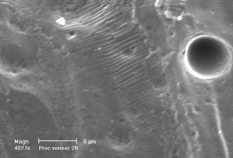
The clear details obtained from replicas viewed here at 4027x. Twist hackle looking like ripples are visible perpendicular to a wake hackle (detailed view of Fig. 10). The twist hackle are obtained from final lateral link up of overlapping crack segments.
Conclusion
The value of replicas in the fractographic analysis of failed ceramic restorations has been demonstrated using two clinically failed crowns. The identification of the crack's origin and its direction of propagation was possible after recognizing and interpreting characteristic fractographic markers such as hackle lines, arrest lines and wake hackle. These replica analyses showed fractographic evidence explaining the causes of the failure and thus helped in preventing future errors in design. The authors therefore strongly encourage dentists to investigate the failure of their ceramic restorations using the intra-oral replica technique. Either the replica and/or recovered failed fragments may then be subjected to fractographic analysis.
Acknowledgments
This work is supported in part by NIH Grant DE 14534.
Footnotes
Publisher's Disclaimer: This is a PDF file of an unedited manuscript that has been accepted for publication. As a service to our customers we are providing this early version of the manuscript. The manuscript will undergo copyediting, typesetting, and review of the resulting proof before it is published in its final citable form. Please note that during the production process errors may be discovered which could affect the content, and all legal disclaimers that apply to the journal pertain.
References
- 1.Kelly JR, Campbell SD, Bowen HK. Fracture-surface analysis of dental ceramics. J Prosthet Dent. 1989;62:536–41. doi: 10.1016/0022-3913(89)90075-9. [DOI] [PubMed] [Google Scholar]
- 2.Kelly JR, Giordano R, Pober R, Cima MJ. Fracture-surface analysis of dental ceramics: clinically-failed restorations. Int J Prosthodont. 1990;3:430–40. [PubMed] [Google Scholar]
- 3.Thompson JY, Anusavice KJ, Morris H. Fracture surface characterization of clinically failed all-ceramic crowns. J Dent Res. 1994;73:1824–32. doi: 10.1177/00220345940730120601. [DOI] [PubMed] [Google Scholar]
- 4.Kelly JR. Fractography of Dental Ceramics. In: Varner JR, Quinn GD, editors. Fractography of Glasses and Ceramics IV. Vol. 122. Westerville, OH: American Ceramic Society; Ceramic Transactions; 2001. pp. 241–51. [Google Scholar]
- 5.Quinn JB, Quinn GD, Kelly JR, Scherrer SS. Fractographic analyses of three ceramic whole crown restoration failures. Dent Mater. 2005;21:920–29. doi: 10.1016/j.dental.2005.01.006. [DOI] [PubMed] [Google Scholar]
- 6.Taskonak B, Mecholsky JJ, Jr, Anusavice KJ. Fracture surface analysis of clinically failed fixed partial dentures. J Dent Res. 2006;85:277–81. doi: 10.1177/154405910608500314. [DOI] [PMC free article] [PubMed] [Google Scholar]
- 7.Scherrer SS, Quinn JB, Quinn GD, Kelly JR. Failure analysis of ceramic clinical cases using qualitative fractography. Int J Prosthodont. 2006;19:151–58. [PubMed] [Google Scholar]
- 8.Rice RW. Ceramic fracture features, observations, mechanisms and uses. In: Mecholsky JJ Jr, Powel SR Jr, editors. Fractography of ceramics and metal failures, ASTM STP 827. Philadelphia: American Society for Testing and Materials; 1984. pp. 5–103. [Google Scholar]
- 9.Fréchette VD. Advances in Ceramics. Vol. 28. Westerville, OH: American Ceramic Society; 1990. Failure analysis of brittle materials. [Google Scholar]
- 10.Varner JR. Descriptive fractography. In: Schneider SJ, editor. Ceramics and glasses, vol 4, Engineered Materials handbook. Metals Park, Ohio: ASM International; 1991. pp. 635–44. [Google Scholar]
- 11.Quinn GD. Special Publication 960-XX. National Institute of Standards and Technology; Gaithersburg, MD: 2006. Recommended practice guide for fractography of ceramics and glasses. [Google Scholar]
- 12.ASTM C1322-05a. Standard practice for fractography and characterization of fracture origins in advanced ceramics. ASTM International; West Conshohoken, PA: 2005. [Google Scholar]