

Abstract
This paper will outline the reasons that many radiology practices are converting to digital mammography. In addition, we will provide basic information on the issues that must be considered in making the transformation. These include technical matters regarding image display, storage and retrieval, as well as clinical and ergonomic considerations.
Why Should a Radiology Practice Convert to Digital Mammography?
Digital mammography has been on the horizon as a tool for breast cancer detection and diagnosis since the early 1990’s when the National Cancer Institute funded the International Digital Mammography Development Group (1). The first clinical digital mammography system received Food and Drug Administration approval in early 2000. Despite high hopes, adoption of this new technology has been slower than anticipated. Besides its high cost and the unwillingness of insurers to provide higher reimbursement for the more expensive technology, the dissemination of this promising tool undoubtedly was slowed by a lack of data supporting improved diagnostic accuracy. Early studies comparing digital and film mammography (2-5) showed no significant difference between digital and film mammography, with digital in fact performing non-significantly slightly worse than film when Area under the Receiver Operator Curve (AUC) or cancer detection rate was measured. These early studies were limited in that they used only one digital system versus film and their sample size was relatively small.
There have been two larger studies published recently that have added impetus to the more widespread adoption of digital mammography. These are the Oslo II Trial and the Digital Mammographic Imaging Screening Trial (DMIST)(6,7).
The Oslo II study enrolled 25263 women who were randomized to either film or digital mammography for breast cancer screening. The rate of cancer detection across the entire population and for the group of women ages 50 to 69 years was greater for digital than for film (overall detection rates 0.41% for film and 0.59% for digital, p=0.06, and 50-69 age group detection rates 0.54% for film and 0.83% for digital, p=0.053). These results approached statistical significance. The trend in cancer detection rate for women under 50 favored digital (0.22% for film and 0.27% for digital). Recall rates in all population subgroups were statistically significantly higher for digital than film without a significant difference in positive predictive value (6). The results of the Oslo II study may not be immediately generalizable to the practice of mammography in the US since the number of readers was quite small, only one digital mammography system was compared to film, and the study was performed in Norway where the breast cancer screening paradigm is different than that used in the US. This latter point is evidenced by recall rates in the study ranging from 2.5-3.8% (6), while one recent large consortium study found the mean recall rate for the middle two quartiles of US radiologists to be 9.8% (8).
DMIST, funded by the National Cancer Institute under the auspices of the American College of Radiology Imaging Network, enrolled 49528 women at 33 institutions in the US and Canada, with 42760 evaluable cases. Women underwent both digital and film mammography. A detailed description of the study methodology is provided elsewhere (9). Five different digital machine types were utilized by 164 radiologists, with each patient’s digital and film mammograms read independently by two separate readers. The digital systems that were included in the study were the Fischer SenoScan (Fischer Medical Corporation, Denver, Colorado), the Fuji 5000 Computed Radiography (CR) System for Mammography (Fujifilm Medical Systems USA, Stamford, CT), the General Electric Senographe 2000D (GE Healthcare, Milwaukee, Wisconsin), the LORAD/Trex Digital Mammography System (Hologic Inc, Bedford, Massachusetts) and the LORAD/Hologic Selenia Full Field Digital Mammography System (Hologic Inc, Bedford, Massachusetts).
DMIST showed that, for the entire population of women, there was no significant difference in diagnostic accuracy, as measured by AUC between digital and film mammography for breast cancer screening (difference in AUC was 0.03, p=0.182). However, for women with dense breasts, women under age 50, and pre- and perimenopausal women, digital was statistically significantly better, even after accounting for multiple comparisons. The difference in AUC for these three groups was 0.106 for women with dense breasts (p=0.0033), 0.151 for women under age 50 (p=0.0023), and 0.149 for pre- and perimenopausal women (p=0.0022). The corresponding differences for women with fatty breasts, women ages 50 and over, and postmenopausal women were -0.03 (p=0.32), 0.004 (p=0.87) and -0.02 (p=0.55), respectively. (Negative numbers indicate that the AUC for film was higher than for digital.)(7) (Table 1)
Table 1.
AUC, Difference in AUC, Sensitivity and Specificity and Positive Predictive Values-1 in DMIST for different population subsets (7)
| AUC Digital | AUC Film | AUC Difference | Sensitivity Digital | Sensitivity Film | Specificity Digital | Specificity Film | PPV1 Digital | PPV1 Film | |
|---|---|---|---|---|---|---|---|---|---|
| All | 0.775 (0.020) | 0.744 (0.022) | 0.032 (0.024) | 0.697 (0.029) | 0.657 (0.030) | 0.918 (0.001) | 0.917 (0.001) | 0.048 (0.004) | 0.045 (0.003) |
| Age <50 | 0.843 (0.030) | 0.692 (0.050) | 0.151* (0.050) | 0.780* (0.054) | 0.508* (0.065) | 0.901 (0.003) | 0.901 (0.003) | 0.032 (0.005) | 0.021 (0.004) |
| Age ≥50 | 0.755 (0.024) | 0.751 (0.025) | 0.004 (0.027) | 0.672 (0.034) | 0.703 (0.033) | 0.926 (0.002) | 0.926 (0.002) | 0.059 (0.005) | 0.061 (0.005) |
| Pre/peri Menopausal | 0.815 (0.030) | 0.666 (0.046) | 0.149* (0.049) | 0.716 (0.050) | 0.506 (0.056) | 0.904 (0.002) | 0.902 (0.002) | 0.037 (0.005) | 0.026 (0.004) |
| Post Menopausal | 0.758 (0.025) | 0.775 (0.024) | -0.016 (0.027) | 0.695 (0.036) | 0.737 (0.034) | 0.926 (0.002) | 0.927 (0.002) | 0.057 (0.005) | 0.061 (0.005) |
| Dense Breasts | 0.785 (0.025) | 0.679 (0.033) | 0.106* (0.036) | 0.696 (0.041) | 0.552 (0.044) | 0.906 (0.002) | 0.902 (0.002) | 0.045 (0.005) | 0.034 (0.004) |
| Nondense Breasts | 0.762 (0.030) | 0.793 (0.028) | -0.031 (0.031) | 0.698 (0.040) | 0.760 (0.038) | 0.928 (0.002) | 0.931 (0.002) | 0.052 (0.005) | 0.059 (0.006) |
Numbers in Parentheses are Standard Errors
Negative Numbers indicate film AUC is greater than digital AUC
p is significant at <0.0033 to allow for multiple comparisons.
Measurement of sensitivity, specificity, and Positive Predictive Value 1 (PPV1) across the entire study population also showed no differences between digital and film mammography. For women under age 50, the sensitivity of digital mammography was statistically superior to that of film, 0.78 versus 0.51 (p=0.002). Similar trends were evident in the sensitivity comparisons in the other population subsets where AUC was better for digital than film. There were no differences in specificity or PPV1 measured in DMIST, either across the entire population or in the subpopulations where AUC for digital significantly exceeded film. These values are shown in Table 1 (7).
There has been great interest in the reasons behind the DMIST results, including understandable concern about the performance of digital mammography in other population subsets. Those interested in breast cancer screening worry that there must be a population subset for which film outperformed digital for the results to be similar in the entire population while digital outperformed film in some population subsets (10). In addition, the cost-effectiveness of this technology given its relative performance in the overall population is of great concern. These topics and a careful review of the DMIST cancer cases by experts in order to ascertain the causes for these results are ongoing and will be published shortly.
One factor not previously published but which is of great interest to radiologists is the performance of the individual machine types in DMIST. Because machine types were not represented in equal numbers in the trial, and all of the Trex/Hologic units were replaced mid-trial by the Selenia Hologic machines (both from Hologic Corporation, Danbury, CT), patient accrual utilizing the various machines was quite variable. See Table 2 for the number of patients and cancers detected per machine type in DMIST. While there were no significant differences in AUC, sensitivity, specificity and PPV1 measured between digital and film by machine type, the ability to measure such differences varied substantially across the various manufactures. Because of the very small number of cancers included in the study that were imaged using both of the Hologic systems (22 all together for both systems), estimates of AUC and sensitivity had extremely wide confidence intervals and may not be reliable. The Receiver Operator Characteristic (ROC) curves for the other three manufacturers are shown in Figures1a, 1b and 1c.
Table 2.
Numbers (%) of Evaluable Cases and Cancers per Machine Type in DMIST
| Machine Type | Evaluable Cases | Cancers |
|---|---|---|
| Fischer | 10103 | 84 (25.1) |
| Fuji | 8957 | 60 (17.9) |
| General Electric | 19250 | 169 (50.4) |
| Hologic Trex | 1483 | 6 (1.8) |
| Hologic Selenia | 2967 | 16 (4.8) |
| TOTALS | 42760 | 335 |
Figure 1.
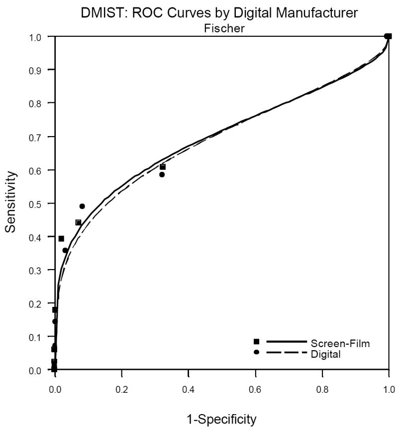
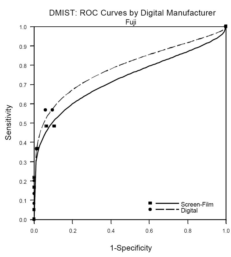
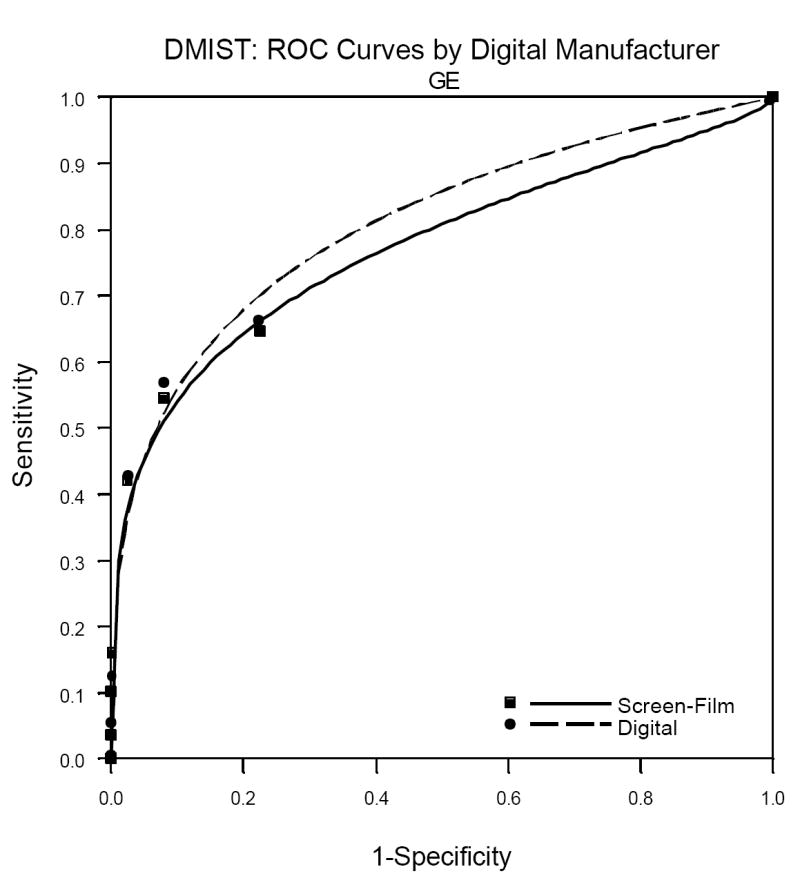
a. Fuji Digital versus Film ROC analysis.
b. Fuji Digital versus Film ROC analysis.
c. General Electric Digital versus Film ROC analysis.
Table 3 shows the AUC, sensitivity, specificity and PPV1 for the three manufacturers for whom there were 60 or more cancers in the study. It is important to remember when viewing the relative performance of the three machine types shown in this table that it is not readily evident how to compare the performance of digital across the manufacturers because patients and readers varied across the manufacturers. That is, differences in our estimates of performance of the various machine types may be due to differences in patient and reader populations, not due to differences in the characteristics of the machines themselves. This is confirmed by the comparison of film mammography across the three populations of readers and patients, with AUC for film varying from 0.695 to 0.775.
Table 3.
AUC, Difference in AUC, Sensitivity, Specificity and Positive Predictive Values 1 (PPV1) in DMIST by machine type
| AUC Digital | AUC Film | AUC Difference | Sensitivity Digital | Sensitivity Film | Specificity Digital | Specificity Film | PPV1 Digital | PPV1 Film | |
|---|---|---|---|---|---|---|---|---|---|
| All | 0.775 (0.020) | 0.744 (0.022) | 0.032 (0.024) | 0.697 (0.029) | 0.657 (0.030) | 0.918 (0.001) | 0.917 (0.001) | 0.048 (0.004) | 0.045 (0.003) |
| Fischer | 0.688 (0.045) | 0.695 (0.045) | -0.007 (0.049) | 0.619 (0.061) | 0.651 (0.060) | 0.908 (0.003) | 0.916 (0.003) | 0.041 (0.006) | 0.046 (0.007) |
| Fuji | 0.788 (0.054) | 0.730 (0.063) | 0.058 (0.068) | 0.727 (0.067) | 0.591 (0.074) | 0.934 (0.003) | 0.930 (0.003) | 0.052 (0.009) | 0.040 (0.008) |
| General Electric | 0.809 (0.024) | 0.775 (0.028) | 0.034 (0.031) | 0.709 (0.040) | 0.685 (0.041) | 0.917 (0.002) | 0.917 (0.002) | 0.054 (0.006) | 0.052 (0.005) |
Numbers in Parentheses are Standard Errors
Negative Numbers indicate film AUC is greater than digital
There were no comparisons where p is significant at <0.0033.
Based on the results of DMIST, the authors of this paper believe that there is ample reason to consider converting to digital mammography, at least for the patient populations for which DMIST showed improved diagnostic accuracy of digital over film. Other reasons to consider the conversion also exist and are given in more detail in the sections that follow. These include the ease of image storage, retrieval and transmission, including the ability to get second opinions from other radiologists at remote sites. In addition, if breast imaging is the only non-digital part of the entire radiology department, the savings in costs in eliminating film processing, storage and display for the department may be substantial, although we are not aware of any formal studies documenting those reductions in cost, and the DMIST cost-effectiveness analysis will take the payer’s rather than the provider’s perspective.
Technical Issues to Consider in Converting to Digital Mammography
Because of the demonstrated enhanced performance in some population subsets with DMIST, there has been increased impetus to convert to digital mammography. There are many technical issues to consider before a transition occurs. In this section of the paper, we will describe those technical issues in detail.
Image Display Issues
In order for the technologist and radiologist to perform and interpret digital mammography images correctly and expeditiously, understanding the issues that surround image display is important. The first aspect of understanding display of an image is to understand the image itself. Digital mammograms start as a pixel map, with a numeric value in each pixel. These numeric values are called analog to digital units (ADU). They basically represent the amount of x-ray exposure to the digital detector in that pixel location. So, as one would expect, the highest ADU counts will be in pixels where only air is between the tube and the detector surface, and the lowest counts where dense structure like bone or metal are present. The number and size of pixels available in the detector varies between vendors. Currently, in full field digital mammography units, pixel sizes are 50, 70 or 100 microns in diameter. As in other modalities, as pixel size diminishes, spatial resolution improves, but noise increases. So, the quality of the end image cannot be surmised from pixel size alone.
After the ADU map is created, the unit then performs multiple processing algorithms to produce a readable image (11, 12). Some of the algorithms are intended to correct for detector inhomogeneities and others are meant to manipulate the acquired data in order to render an interpretable image. One common algorithm is called thickness equalization. This algorithm enhances the signal in the fatty subcutaneous region so that it is readily visible without the user having to manually adjust the window width and window level settings during interpretation. Other imaging processing algorithms are used in an effort to make things like mass borders and calcifications more obvious (11, 13). All of these algorithms are currently proprietary to each manufacturer. The final resultant images that are produced are called the “For Presentation” images. These are the images that radiologists interpret. Every digital mammography unit also produces partially processed images. These are commonly called raw images, but they in fact are not raw images; they are images that have had some but not all of the processing applied to them. These are more correctly called “For Processing” images. It is these “For processing” images that the CAD vendors use to apply their algorithm.
DICOM and IHE
Each digital image that is produced also has a DICOM (Digital Imaging and Communications in Medicine) header attached to it. The header carries all information necessary for accurate display, storage and retrieval of the image such as patient demographics, acquisition parameters and display requirements [Figure 2]. Each piece of information that is recorded in the header has a specific location that is assigned to it by the DICOM standard. If each manufacturer uses the DICOM standard and interprets the meaning of the standard in the same way, then information can be shared. If however, the standard is interpreted differently by two vendors and any piece of information is stored in a different location in the header, then the pieces of equipment cannot communicate that information. This is a DICOM incompatibility. One of the main reasons that digital transitions are complicated is that these DICOM incompatibilities are common, not only between vendors, but between different generations of equipment from the same vendor. Like all else in medicine, the standard has evolved and changed with advances in technology and experience. Multiple DICOM committees exist to keep the standards up to date. Frequently, the committees accept change proposals for the standard. Vendors then must implement the new standard and make changes in their equipment in order to be compliant. For equipment that is already deployed in the market, sometimes it is not cost beneficial for vendors to make the necessary DICOM updates. As a result, when a facility tries to add a new piece of equipment into an older system, there are often DICOM incompatibility problems. These may be corrected with software patches or site specific workarounds. In some cases though, these differences are so significant that old equipment must be replaced or choices for new equipment are limited.
Figure 2.

Example of a DICOM header.
Unfortunately, even when vendors comply with the same version of the DICOM standard, incompatibilities still exist between products as a result of variable interpretations of the standard. In 1998, a joint effort by the Radiological Society of North America (RSNA) and the Healthcare Information and Management Systems Society (HIMMS) was created to address this problem. The effort is called Integrating the Healthcare Enterprise (IHE). IHE defines how standards like DICOM and Health Level 7 (HL-7) should be used by defining the transactions that must occur between pieces of equipment in order to solve clinical problems (14, 15). These precise scenarios, called profiles, allow integration of heterogeneous information systems. Each profile is meant to solve a related group of clinical problems. IHE also uses a specific vocabulary in order to avoid confusion. The profiles, together with the vocabulary make up the Technical Framework (16). When vendors follow the IHE profiles and DICOM standards, then their equipment can be integrated into a facility far more easily.
FDA Classification
In 1999, the Food and Drug Administration (FDA) classified full field digital mammography (FFDM) as a class III device. Part of the FDA requirement for product approval has been that vendors ensure the integrity of the image from acquisition to display, storage, and print. As a result, products have evolved as insular, proprietary systems that function well internally, but have little ability to communicate with other equipment. For users, that meant that the only choice to be made was which acquisition unit to purchase; the workstation, monitors and printer that were developed to function with the acquisition unit had to be used for any images produced by that gantry. In 2001, the FDA allowed printers to be broken off from this chain and have separate clearance as class II devices. Shortly thereafter, in 2002, the FDA chose to allow other third-party monitors and then diagnostic workstations to apply for approval for digital mammography display. So, now, users are free to use any FDA approved workstation for interpretation, but unfortunately, FDA approval for display does not mean that the images are actually displayed correctly. So, the user must be careful.
Compatibility
The problems with display of images on foreign workstations stem from the different pixel sizes at acquisition, variable interpretations of the DICOM standard, and proprietary development of products. The most obvious discrepancy between the systems is pixel size at acquisition. There are four ways to display a digital image on soft-copy: fit to viewport, true size, full resolution, and magnification. In the fit to viewport mode, the image is scaled to fit on the portion of the monitor to which it is allocated. This is accomplished by displaying an average ADU for a group of adjacent pixels. For instance, an image acquired at 70 microns might be displayed at 120 micron resolution. The smaller the pixel size of acquisition, the more the image will have to be down sampled for display, so a breast imaged at 50 microns will look smaller to the radiologist than the same breast imaged at 100microns [Figure 3]. To complicate matters more, some smart applications can identify skin line and display only the breast area while ignoring the air around the breast. Others cannot do this and have to display the entire detector surface in the display. Mammograms displayed on workstations that don’t have skin line detection capability will therefore look smaller than the same images displayed on smart workstations where skin line is known. As a result, if a patient has mammograms done on units of differing pixel size from year to year, and the workstation cannot adjust display to compensate, evaluating the images for lesion growth and developing asymmetries is very difficult. Some smart workstations can now make the images look the same size by scaling the display, in the fit to viewport mode, based on acquired pixel size [Figure 4].
Figure 3.
Same patient imaged in two consecutive years on systems with different pixel pitch. In this “fit to viewport” mode, the upper images, which are acquired at 50 microns look smaller than the lower images which were acquired at 100 microns.
Figure 4.

Same images as in figure 2. Now in the “fit to viewport” mode, the images are all scaled to be displayed at the same size. This scaling allows the radiologist to compare the images for developing densities and lesion size changes.
The second way to display images is true size. True size means that the display matches the actual physical size of the breast. This display is important for procedures such as stereotactic core biopsy and surgery, so that a lesion’s size and location relative to skin, nipple and chest wall can be easily ascertained. Some workstations are incapable of displaying true size currently.
The third display is full resolution. In this mode, each acquired pixel from the acquisition detector is displayed by one pixel on the monitor at the diagnostic workstation. Therefore, by definition, this is the mode where all of the information in the acquisition is presented. Full resolution is important for evaluation of subtle lesions like faint calcifications or mass margins. Because acquisition matrices are all larger than display matrices, unless the breast is small and the workstation smart enough to know skin line and exclude the area around the breast, this mode requires that the user can move around the displayed breast to see it all (pan function) or can magnify subsets of the breast (the zoom function).
The fourth mode of display is magnification. In this mode, an acquired pixel is displayed by more than one pixel on the workstation. Display can be achieved by use of a segmental magnification such as quadrant zoom, where the radiologist steps through tiles of the image, a magnification glass that is moved around the image, or magnification of the entire image and then use of the pan function. Inspecting images at resolutions greater than acquisition is performed by a variety of interpolation algorithms, and may make review of mammograms easier in some instances, but does not add any additional information to the acquired data.
In order for the radiologist to know what amount of data down-sampling or magnification is being displayed at any given time in a hanging protocol, some workstations display the zoom(or magnification) factor(16).
Another significant problem is the orientation of images. Images are hung correctly in display protocols when both the acquisition unit and the workstation use the correct orientation tag. Several types of images have a potentially confusing orientation, such as superolateral-to-inferomedial obliques (SIO), caudocranial (FB, from below) views and cleavage (CV) views. Without proper use of this information, any view, but especially these views, will be hung incorrectly, potentially leading to misinterpretation by the radiologist.
Yet another problem is the different shape of the window width/window level curve (called the volume of interest lookup table [VOI LUT]). Some vendors produce images that are meant to be displayed using a sigmoidal curve, others a linear slope. If the workstation cannot apply the correct curve, the image will be significantly degraded. [Figure 5] This is an example of the problems that result when systems evolve in a proprietary way. Along the same lines, any workstation that cannot identify skin line will not be able to keep the area around the breast dark if the radiologist manually increases the window level and or widens the window width. In this situation, the area around the breast becomes increasingly brighter and image contrast is degraded [Figure 6].
Figure 5.

Same mammogram (all for presentation images) displayed correctly on the bottom with the sigmoid LUT and incorrectly on the top with a linear LUT.
Figure 6.

The Right MLO is shown as it originally appears on the diagnostic workstation. The Left MLO view has had a manual widening of the window width and increase of the window level at the diagnostic workstation. This common manipulation has changed the blackness of the image around the breast, thus decreasing the apparent contrast in the breast tissue and degrading the image.
Processing Algorithms
The appearance of a digital mammogram, to a large degree, is due to the image processing that is applied to it. Currently, most manufacturers offer no choice in processing and change their algorithms from time to time. These changes can significantly alter the appearance of the mammogram [Figure 7]. In addition, users have little or no information available to them about the algorithms that they are using. For the radiologist, this creates a challenge to relearn what normal tissue looks like, each time the algorithm is changed or each time another vendor’s equipment is purchased. The processing algorithm differences, along with the sizing issues already discussed make comparisons between years difficult.[Figure 8] Several authors have shown that different processing algorithms may be better or more preferred depending on the tasks, lesions and systems (11-13, 17-20). Two vendors currently offer more than one processing algorithm for interpretation. For these systems, it is up to the radiologist to choose which algorithm is preferable because, to date, there has been no study showing that one kind of processing is of superior diagnostic quality to another. Even if a facility chooses to purchase acquisition units all from the same vendor, that facility will still have to contend with images from almost every vendor, because patients will bring prior digital images from the outside for comparison.
Figure 7.

Same patient imaged two consecutive years in a row on the same digital mammogram unit. The processing algorithm changed in the interval, resulting in a different look to the mammogram.
Figure 8.

Same patient imaged in two consecutive years. On the top, the images were acquired at 50 microns and on the bottom the images were acquired at 70 microns. The workstation is displaying the images in the “fit to viewport” mode, but cannot scale the images to the same size. That difference along with the disparate processing between vendors makes comparison of this patient’s mammogram very difficult.
Prior Mammograms
Several options exist for display of prior mammograms. If the prior studies are analog, then the radiologist must decide if the images should be hung on an alternator adjacent to the diagnostic workstation or if the images should be digitized and placed in a hanging protocol for soft-copy comparison. The advantage of digitization is that the prior images will be in much closer proximity to the current digital mammogram. Also, all of the luminance issues surrounding the difference in light output between traditional alternators and computer monitors are solved with digitization and soft-copy display of prior images. Analog digitizers typically produce a 50 micron image, and so all of the sizing problems that were discussed previously will apply to these images as well. The algorithms that process the digitized analog images are evolving rapidly. These images are not FDA approved for primary interpretation and do not replace the original analog images for medical-legal purposes or for ACR requirements.
IHE Profiles
To ensure that any digital mammogram can be correctly displayed, the Mammography Image Profile is necessary (16). This profile, written in 2006, was developed to resolve the display problems that are nearly ubiquitous when mammography images are displayed on third-party workstations. For example, it allows images of different pixel sizes to be scaled to the same size for display so that the radiologist can evaluate changes in lesion size or developing asymmetries. It also clearly defines image orientation, to solve the common problem of left images hanging like right images, as well as addressing the window width/window level look up table differences and the background blackness maintenance. CAD display issues, annotations, and problems with printer integration are also addressed with this profile.
Storage Considerations
Image Sizes
Both short term and long term storage needs for digital mammography are significant for several reasons. First, because the pixel sizes are small and the matrices large, the images are big, ranging in size from 8.8 to 52 MB per view. Therefore, a standard four view mammogram can be up to 208 MB. Secondly, as discussed previously, both “for processing” and “for presentation” data sets are produced for every image. If a facility elects to store both of these types of images, storage needs double. CAD files are small so the decision to store them on the long term archive is more a medical-legal decision than a storage space decision. Similarly, if annotations are stored as a DICOM overlay, then the storage added is insignificant. However, if the workstation only allows annotated images to be saved and stored as a screen capture, then each of these images is the same size as the original view and so they should be considered in the calculation of storage requirements.
Compression
Currently, visually lossless compression is acceptable for storage. These ratios typically range from 1.5 to 3:1, and so only moderate savings in storage space are realized. Lossy compression ratios higher than 3 or 4:1 are currently not recommended, mainly due to concerns about the possible inability to evaluate subtle calcifications at these higher ratios (21). To date, several studies have shown that compression ratios far higher (as far as 80:1) might not result in loss of diagnostic information (22-24). However, studies evaluating the ability to detect and accurately characterize lesions with lossy compression ratios are still needed to answer this clinical question with confidence. Until that time, due to the medical-legal issues surrounding the maintenance of the originally interpreted data and the important need in mammography to have diagnostic quality prior images for comparison, lossy compression is not recommended (21). As a result, if a practice produces 100 digital mammograms per day, stores both “for presentation” and “for processing” data, and the images are compressed on average 2.5:1, the storage needs range from 7 GB to more than 16 GB per day.
Prior Studies
One of the most important considerations in determining storage requirements is the prior analog images. For workflow purposes, many facilities elect to digitize the prior analog mammograms so that they can be displayed in soft-copy immediately adjacent to the current digital study. Currently, these digitizers produce 50 micron images, with image sizes of 35 to 58MB per view, depending on the size of the film. If these images are stored in the archive, the storage space required again increases by a factor of 2 for each prior year that is digitized. Presuming that a facility produces 20,000 digital mammograms per year, and digitizes and stores 2 prior analog studies, the long term storage requirements for that facility would range from 6.3 to 13.4TB, per year, using a lossless compression ratio of 2.5:1. Short term storage is also affected by the file sizes. In order to maximize workflow efficiency, readily available prior studies are critical because, often, multiple prior images are reviewed in the course of interpretation of a mammogram. So, as facilities accumulate years of digital mammograms, or digitize multiple prior years of analog studies, the need to have many (or all) prior studies quickly accessible will be important. This means that the on-line storage space necessary will increase over time and the quick ability to retrieve many old studies (pre-fetch capability) of the system will have to be robust. In facilities where the on-line storage and or the pre-fetch capabilities of the pre-existing Picture Archive and Communication System (PACS) cannot meet the workflow needs of digital mammography, a mini-PACS solution can be implemented. The downside of a mini-PACS solution is that it continues to isolate digital mammography from the rest of the system so that in order to view a digital mammogram, a workstation would have to be networked to it. If that workstation also functions as a multimodality workstation, then possibly it would also have to be networked to the main PACS and even the Radiology Information System (RIS).
Push vs. Pull
The configuration of how the images arrive at the diagnostic workstation also factors into the amount of storage necessary. Several systems follow a “push” model of moving data where the images are sent either by a predetermined mechanism or manually to each workstation. In a facility where there are multiple acquisition units and multiple diagnostic workstations, all of the images from every unit and the prior images from offline storage may be pushed to every workstation. Not only does this create a lot of network traffic, but it also requires more on-line storage space for each workstation. If a “pull” model is used, then the images are pulled to the diagnostic workstation, again either by a predetermined specification or manually. From a storage standpoint, this is more efficient than the push model, but could have some display speed implications. Many systems use a combination of a push and pull model to maximize the benefits of both.
Network Issues
Hand in hand with storage needs are transmission concerns. The bandwidth of the network can have significant impacts on display speed, and therefore radiologist workflow. For example, if a facility has an Ethernet 100-base T network, then a 4-view mammogram with lossless compression can be transmitted in approximately 1 minute. If the facility uses a cable network, then it can take several minutes to transmit the study. Not only are these transmission times long, but the amount of bandwidth necessary to move mammography images impacts the transmission abilities of all the rest of the data moving through the system. In order to avoid congestion in the network and avoid workflow slowdowns, many facilities pre-fetch prior studies to on-line storage prior to the time that the radiologist logs on to read.
Clinical and Ergonomic Issues to Consider In Converting to Digital Mammography
General Clinical Considerations
Factors that must be considered in converting a busy breast imaging practice from film to digital mammography include how many digital mammography units to acquire, whether there is more than one site where mammography is performed, how many sites there are where mammography is interpreted and whether there is a practice PACS system already in existence.
The more mammographic units in the practice and the more sites where mammography is performed and interpreted, the more complex the issues around conversion become. The decision on how many units to convert and if eventually all units are to be converted and how quickly to do this needs to be determined early in the process. If only one unit is converted at one or at multiple sites for a period of time, then issues may arise as to who is examined on the digital versus the film units. Patients and referring physicians may request or even demand one type of exam.
If the practice has more than one site, another issue that will occur is whether all units at one site are converted first or if the conversion to digital is partial at each site. The speed of conversion to an all-digital practice, if that is the goal, will depend very much on the available funding from the practice administration both within the radiology department and within the hospital or medical group administration. As many radiologists can testify, slower conversion is more painful as one still has to be able to interpret film as well as digital mammographic exams. Some of the advantages of a digital system, such as decrease and eventual lack of necessity for a film storage area and associated personnel, lack of need of a dark room and processor, and ease of transmission of the images will not be fully realized until a practice completely converts to all-digital.
If not all the units at a single site are converted within one year, some patients will still be getting film exams. This will prolong the time needed to have a way to interpret both the digital and the film exams. Some practices are storing current exams after interpretation as digital images on their departmental PACS utilizing one of the CAD system digitizers to convert the film images (25). This will provide digital comparisons with back-up of the films if needed the next year. If the choice is to convert one site before the others, patients and referring physicians may want to send patients only to the site where the digital units are available. The goal should be to convert all the units at all sites as quickly as possible to take advantage of digital conversion.
Once a practice has decided on the general speed of conversion to digital mammography, a decision as to which digital units to purchase must be made. While radiologists and administrators are used to buying whichever film mammography unit is available at the best price with the add-ons they want at that particular time, this is less of an option with digital units. Film units produce a common viewable image that is very similar no matter which manufacturer’s equipment is utilized. As explained in detail above, digital mammographic images are not as easily interchangeable and comparable (26).
Patient Throughput Issues
In addition, the decision as to whether to use the digital unit or units for screening or diagnostic mammography or both may have to be made. As throughput of patients on the digital systems is typically faster than on film units, and as the cost of the unit is much higher, the decision is often made to use the digital unit in the screening setting to ensure maximum usage of the digital units. If using digital for screening, then additional imaging may be performed with film mammography or digitally. This can lead to difficulties in evaluation of current additional views and then comparison of studies at 6 month or yearly follow-up. Display size differences will affect evaluation of both calcifications and masses and different processing algorithms can make it difficult to even see the same area of concern, particularly if it is a vague area of asymmetry or a cluster of calcifications. Careful attention to these factors is required.
Whether using the digital units for screening, diagnostic, or both types of exams, the type of patients examined on the digital units when there are also film units in the system becomes an issue. Some patients and their referring physicians may insist on digital imaging whether or not, based on the DMIST results, it will improve detection of malignancy. If the practice has only a limited number of digital units or only digital units at one site, this can become a scheduling nightmare. Even if the practice protocol is to try to image with digital units only patients shown to have benefited from digital imaging in DMIST (by prescreening) and if the patient’s last exam was a digital one, if there are not enough digital units within the practice, inefficiencies in running the schedule of patients for examination each day can occur.
Many practices that have already begun to acquire digital mammography units have placed these in the screening rather than the diagnostic setting. The speed with which patients can be imaged and their exams checked by the technologist for the digital radiography (DR) units is such that patient room time for a screening exam can be as low as 5 minutes. Thus, there is the potential to utilize fewer mammographic units to produce the same number of studies. For DR units, it has been reported that one digital unit can replace 2 film units (27). With computed radiography (CR) units, since the images still have to be processed, and images reviewed afterwards, increased throughput of patients is similar to film units although film handling times are eliminated after completion of the exam. Newer and improved CR mammography systems do produce images faster at a much lower cost (28).
Use of digital mammographic units in the diagnostic area can also result in increased throughput. Again the main speed advantage is realized only with the use of DR (not CR) units. Images can be immediately checked to ensure that they include the area of concern that is being evaluated and repeated without having to take the patient out of the room and then brought back in. Needle localization procedures can become almost real time with localizations taking as little at 10-15 minutes from initial imaging to completion of the procedure (25). As the technologist does not have to leave the room to develop her films, there is added patient safety as there are always 2 people in the room throughout the procedure. Although CR units take longer, if the image processor is in the room, some time is also saved and, again, 2 people can remain within the room for added patient safety.
Ductograms can be performed more easily with digital imaging as patients do not have to hold still with the needle in place nearly as long. Decision to inject more contrast can be easily made and additional views to better demonstrate the area can be quickly obtained. Use of digital magnification can help in interpreting these studies, without having to move the patient to set up for a direct magnification view with its attendant greater risk for needle displacement.
Newer imaging techniques can be incorporated more easily into practice. Tomosynthesis using digital imaging is already possible although not yet available for purchase. Contrast enhanced imaging can also be more easily performed, although the clinical utility of this technology has not yet been proven.
Speed of conversion
How fast a practice can convert to all-digital depends on human factors as well as financial ones. Technologists, radiologists and physicists have to learn new quality control methods. Currently these are different for each manufacturer’s equipment so again, this may encourage use of only one type of digital unit (29). Efforts are underway to recommend a more uniform approach to digital quality control, which will reduce time and confusion.
Technologists have to learn to use digital units to acquire images, although this is not a time-consuming issue. However, for DR units they also have to learn and be encouraged to utilize all the tools available to review their images before letting the patient leave the room. As the acquisition monitors used by technologists are often of lower resolution than work (interpretation) monitors, and as there is a relatively high level of ambient light in the examination room, technologists should be provided with adequate time to review the images under the best possible viewing conditions to check the images for positioning, compression, and lack of artifacts. Technologists also must have familiarity with the ability to enlarge the images and change the brightness and contrast of the images on the acquisition station.
The order of obtaining the images, if more that one image is necessary in each view to cover the whole breast, becomes important in some of the DR systems. Radiologists want to compare, for example, the same images for each side. However, if the technologist obtains the upper and more posterior breast in the MLO projection on one side first and then the more anterior and inferior portion next and does the opposite on the second side, the images when pulled up for review on the workstation may show the first image of each side obtained in MLO projection and then either the second view shows up automatically or must be manually dragged into the viewing position. For these systems, training all the technologists to obtain the views in the same sequence all the time will result in reduced image manipulation time for the radiologist.
While technologist time is less to acquire the mammograms with digital and especially with DR units, it takes longer for radiologists to interpret them, especially initially. Clearly, with experience, this time can be decreased (27). However, the ability to manipulate the digital image, including magnifying the image and inverting it, takes more time than reviewing a film image even if one uses a magnifying glass and a bright light. Initially, radiologists report that it takes about twice as long to interpret a digital vs. a film mammogram. However, with experience this time will decrease. Those experienced at digital interpretation say that with optimal system setup and reading or hanging protocols on the workstations and experience, the time of interpretation of film and digital exams can be similar. It is also faster when one has old digital rather than film images to compare (30, 31).
Interpretation of digital mammography must be performed on a workstation to take full advantage of the benefits. Practices that routinely print the digital images are limiting interpretation benefits and increasing costs of imaging handling, as now printed images must be hung and removed by a person and the images have to be stored in film jackets, requiring retention of file room space and personnel. Printing images does allow the radiologist to mark areas of concern if the patient needs to be called back for additional imaging so that the technologist has this image in the room at the time of the additional imaging. However, the radiologist can save these marks electronically so that the technologist can pull the marked images onto her acquisition monitor.
Optimization of interpretation time requires that hanging protocols be developed to review the digital images as efficiently as possible. These protocols must be adjusted for more than 2 views of each breast for screening, and to allow review of the current images quickly, with the ability to compare the 2 sides and the CC and MLO view of one side simultaneously. Protocols must allow comparison of several old studies in sequence, ideally without having to drag and drop every image. For diagnostic imaging, all the images should be viewable at full resolution. Ideally, protocols to display routine diagnostic views should be set up and easily retrievable for use during interpretation.
All of these protocols should be radiologist-specific. Standardized hanging protocols are helpful initially but most experienced mammographers have their own preferences on how to review and compare exams, and systems should be easily programmable and adaptable for individual readers. Manufacturer-provided training should include enough time to set up these specific protocols and should include a second training visit that allows for refinement of radiologist-specific protocols after a few weeks of operation.
Where to Interpret Studies
If mammography is performed at only one site and only a small volume is performed, interpretation can be performed at one workstation. Depending on the volume of screening and diagnostic exams, about 2-3 mammographic units require 1 workstation for efficient use of radiologist time. The higher the volume of diagnostic studies, or if the practice is reading screening exams on line, the more workstations are needed, as interruption of interpretation of a digital exam to look at images from another ongoing exam may be more disruptive than with film exams. Separating workstations for interpretation of diagnostic or screening exams can be done and is recommended for more radiologist efficiency, as is already done at many breast centers for interpretation of film exams.
If the practice has several sites where exams are performed, images can more easily be interpreted off-site with digital mammography, although this benefit may not be realized for a couple years after digital is first adopted because of the need for comparison with old film examinations. Initially, the patient’s old films have to be transported to the interpretation site and hung for comparison with the new digital studies. This of course will not be an issue for practices that digitize prior exams.
Interpretation, particularly of screening mammograms, can be performed off-site using electronic distribution of the images rather than using personnel to transport and hang films. Radiologists, who are in limited supply, do not have to waste time traveling to different sites. For remote locations, even diagnostic exams can be interpreted literally on-line with immediate transmission of the images to the radiologist, who can communicate need for additional images to the technologist by phone or fax and who can give the patient the results immediately by phone (32). This is a major benefit of digital mammography, but may be limited to diagnostic examinations that do not include ultrasound.
For practices with several sites where mammography is performed, more than one place to interpret studies may be needed. Which studies are interpreted at each site has to be determined. Screening exams can be interpreted at a central site for more efficiency and diagnostic cases could be performed separately at each site, possibly only on specific days. For radiologists reading at separate sites, the possibility for consultation with each other on difficult cases is much easier than with films, if exams are digital and sent to departmental or breast imaging specific PACS. This ability to quickly obtain second opinions clearly benefits the patient, as in all of radiology.
How to Configure Reading Rooms
Breast imaging has typically been relegated to small corners of the department with small reading rooms. Although eventually both film alternators and computers with multiple monitors won’t be needed, they will be in most practices for the transition period from film to digital mammography, i.e. for 2 to 3 years. Reading rooms have to accommodate this. Also, the high intensity lights required on the film mammography alternators and the number of computers and monitors required will result in a large amount of heat within the reading room. Planning ideal reading rooms should include the engineering department, so that adequate cooling is available within the reading rooms both for optimal functioning of the computers and the radiologists. Ambient lighting in these rooms has to be easily controlled, and there has to be adequate shielding and easy control of the lights on the film alternators so that digital mammograms can be viewed simultaneously nearby on softcopy display. There also has to be some indirect lighting so any paperwork can be reviewed and keyboards can be seen, and so personnel can safely move around the room. PACS monitors and RIS system monitors should have dark backgrounds or be easy to turn on and off, to avoid the light reflecting off the workstation monitors. If more than one reading station is in the room, separation of the reading areas is necessary. A convenient way to do this is with a dark curtain reaching almost to the ceiling, as traditional moveable panels as used in many departments do not extend high enough to block lights.
Typically, a reading space for mammography interpretation needs a film alternator for the old films at right angles to the 3 monitor workstations for digital interpretation and at least one other computer monitor for connection to radiology information system (RIS) and departmental PACS so that ultrasounds, MRIs and other pertinent studies and reports can be available. In a diagnostic breast imaging reading room, PACS access for interpretation of breast ultrasound and MRI must be readily available. If CAD is used, a computer for this is also needed in the reading room but, for mammography, no separate monitor is needed. For CAD for MRI, some systems need their own monitor in addition to a computer, or they may be able to be reviewed on a departmental PACS monitor. Work space also needs a phone and possibly a dictation system. If using voice recognition, the keyboard for the system where the reports will be reviewed has to be easily accessible.
Careful attention to ergonomic issues in setting up the workspace is recommended. For years, mammographers have leaned forward in order to see the images up close and to review with a magnifying glass. This leads to significant neck and back strain. Film alternators have never been at the correct height for all radiologists who read mammograms. The optimal distance to view images on the digital work stations varies slightly for each radiologist but optimal image distance averages 30-60 cm, with the radiologist looking straight ahead, not up or down. Use of adjustable ergonomic tables and chairs, which can accommodate all the radiologists in your group, is important to reduce eye, neck, and back strain. Keyboards need to be at a height that will reduce wrist and arm strain. This is especially important if radiologists are using a mammography dictation program where the report and statistics are generated immediately.
Clinical Issues Regarding Image Storage and Retrieval
Retrieval of images needs to occur when patients return for additional diagnostic studies or interventional procedures and when they return for short-interval follow-up or for yearly exams. Images also need to be retrieved for conferences or tumor boards, for teaching, for consultation with other radiologists within your practice, and for other physicians to review at the time of an appointment or treatment. Issues regarding retrieval vary with the type of system you are using for interpretation – a manufacturer-specific workstation or a PACS system - and how you are storing your images. Clearly if digital mammography is to be useful, images must be stored electronically and readily retrievable. Who is responsible for image retrieval will vary with the type of image storage you are using. Some ancillary staff, technologists, and radiologists must know how to retrieve prior images. Clearly, if reading on a general PACS system with a dedicated mammography FDA-approved workstation, this is less of an issue.
For a truly digital system to work, the surgeons and other physicians who are used to reviewing mammograms when they see the patients in their offices and operating rooms, must be given access to digital monitors so they can see the images, unless your practice wants to keep printing a lot of images (which can be quite expensive). Other physicians do not need high resolution monitors, since once the radiologist has marked and saved pertinent images, other providers will be able to see the vast majority of the findings well enough to work from them with lower resolution display systems. However, radiologists will have to spend some time training other practitioners on how to look at the images on digital monitors. Surgeons will be able to see specimen radiographs quickly through the system-wide PACS, if the images are obtained digitally.
Consideration must also be given to how images will be sent out when requested to other sites for comparisons or second opinions. Also, how will your practice review digital images from other practices? Will the radiologist reviewing the case have to open it on a regular RIS computer or can or should the images be loaded into your workstation or PACS and reviewed on a mammography approved workstation? The latter is the best way to review outside images rather than on printed digital images. Programs to allow one to copy digital images onto a compact disc (CD) and to open these images are available and one such program should be selected for your practice. As with the rest of digital radiology, CDs or DVDs of the images may be given to patients or sent outside for review or comparison.
Digital Mammography and Paperwork
With a PACS system, requests for exams can be provided on-line rather than on paper. History sheets, often completed by patients, can be quite helpful in providing information pertinent to the mammography interpretation and also are helpful in medicolegal situations. These can be digitized and stored or the same data can be collected using a tablet personal computer (33). To our knowledge, not one of the currently available digital mammography workstations can currently display this sort of data.
Conclusion
In summary, there are many issues to consider in converting a busy breast imaging practice from film to digital mammography but we believe that the clear benefits to the practice and to many of our patients make this effort worthwhile. If the technical, ergonomic and clinical issues can be addressed in a satisfactory manner, breast imaging clinics can be part of a fully-digital radiology practice.
Footnotes
Publisher's Disclaimer: This is a PDF file of an unedited manuscript that has been accepted for publication. As a service to our customers we are providing this early version of the manuscript. The manuscript will undergo copyediting, typesetting, and review of the resulting proof before it is published in its final citable form. Please note that during the production process errors may be discovered which could affect the content, and all legal disclaimers that apply to the journal pertain.
Contributor Information
Etta D. Pisano, Departments of Radiology and Biomedical Engineering, UNC Biomedical Research Imaging Center, UNC-Lineberger Comprehensive Cancer Center, UNC School of Medicine, CB 7000, Room 4030 Bondurant Hall, Chapel Hill, North Carolina, 919-966-9282 (telephone), 919-966-0817 (fax), Etta_Pisano@med.unc.edu
Margarita Zuley, Department of Imaging Sciences, University of Rochester Medical Center, 601 Elmwood Ave, Box 601, Rochester, NY 14642, telephone 585-487-3300, fax 585-334-5519, margarita_zuley@urmc.rochester.edu
Janet K. Baum, Cambridge Health Alliance, Cambridge, Massachusetts, Director of Breast Imaging, Associate Director of Undergraduate Medical Education, Department of Radiology, Cambridge Health Alliance, Associate Professor of Radiology, Harvard Medical School, 1493 Cambridge St., Cambridge, MA 02139, phone: 617-665-1599, fax: 617-665-2428, jbaum@challiance.org
Helga S. Marques, Center for Statistical Sciences, Brown University, Box G-S121-7, 121 South Main Street, Providence, RI 02912, 401-863-2884 (telephone), 401-863-9182 (fax), hmarques@stat.brown.edu
References
- 1.Shtern F. Digital mammography and related technologies: a perspective from the National Cancer Institute. Radiology. 1992;183:629–630. doi: 10.1148/radiology.183.3.1584908. [DOI] [PubMed] [Google Scholar]
- 2.Lewin JM, Hendrick RE, D’Orsi CJ, Isaacs PK, Moss LJ, Karellas A, Sisney GA, Kuni CC, Cutter GR. Comparison of full-field digital mammography with screen-film mammography for cancer detection: results of 4,945 paired examinations. Radiology. 2001 Mar;218(3):873–80. doi: 10.1148/radiology.218.3.r01mr29873. [DOI] [PubMed] [Google Scholar]
- 3.Lewin JM, D’Orsi CJ, Hendrick RE, Moss LJ, Isaacs PK, Karellas A, Cutter GR. Clinical comparison of full-field digital mammography and screen-film mammography for detection of breast cancer. AJR. 2002;179:671–677. doi: 10.2214/ajr.179.3.1790671. [DOI] [PubMed] [Google Scholar]
- 4.Cole E, Pisano ED, Brown M, Kuzmiak C, Braeuning MP, Kim HH, Jong R, Walsh R. Diagnostic accuracy of Fischer Senoscan Digital Mammography versus screen-film mammography in a diagnostic mammography population. Academic Radiology. 2004;11:879–886. doi: 10.1016/j.acra.2004.04.003. [DOI] [PubMed] [Google Scholar]
- 5.Skaane P, Young K, Skjennald A. Population-based mammography screening: comparison of screen-film and full-field digital mammography with soft-copy reading--Oslo I study. Radiology. 2003;229:877–84. doi: 10.1148/radiol.2293021171. [DOI] [PubMed] [Google Scholar]
- 6.Skaane P, Skjennald A. Screen-film Mammography versus Full-Field Digital Mammography with Soft-Copy Reading: Randomized Trial in a Population-based Screening Program – The Oslo II Study. Radiology. 2004;232:197–204. doi: 10.1148/radiol.2321031624. [DOI] [PubMed] [Google Scholar]
- 7.Pisano ED, Gatsonis C, Hendrick E, Yaffe M, Baum JK, Acharyya S, Conant EF, Fajardo LL, Bassett L, D’Orsi C, Jong R, Rebner M on behalf of the DMIST Investigators Group. Diagnostic Performance of Digital vs. Film Mammography for Breast-Cancer Screening. New England Journal of Medicine. 2005;353(17):1773–1783. doi: 10.1056/NEJMoa052911. [DOI] [PubMed] [Google Scholar]
- 8.Rosenberg RD, Yankaskas BC, Abraham LA, Sickles EA, Lehman CD, Geller BM, Carney PA, Kerlikowske K, Buist DS, Weaver DL, Barlow WE, Ballard-Barbash R. Performance benchmarks for screening mammography. Radiology. 2006 Oct;241(1):55–66. doi: 10.1148/radiol.2411051504. [DOI] [PubMed] [Google Scholar]
- 9.Pisano ED, Gatsonis C, Yaffe M, Hendrick E, Tosteson A, Fryback DG, Bassett L, Baum JK, Conant E, Jong R, Rebner M, D’Orsi C. The American College of Radiology Imaging Network (ACRIN) Digital Mammographic Imaging Screening Trial (DMIST): Objectives and Methodology. Radiology. 2005;236:404–412. doi: 10.1148/radiol.2362050440. [DOI] [PubMed] [Google Scholar]
- 10.Keen JD. Digital and film mammography. New England Journal of Medicine. 2006;354(7):765–767. [PubMed] [Google Scholar]
- 11.Pisano E, Cole E, Hemminger B, Yaffe M, Aylward S, Maidment A, et al. Image Processing Algorithms for Digital Mammography: A Pictorial Essay. RadioGraphics. 2000;20:1479–1491. doi: 10.1148/radiographics.20.5.g00se311479. [DOI] [PubMed] [Google Scholar]
- 12.Sivaramakrishna R, Obuchowski N, Chilcote W, Cardenosa G, Powell K. Comparing the Performance of Mammographic Enhancement Algorithms: A Preference Study. AJR. 2000;175:45–51. doi: 10.2214/ajr.175.1.1750045. [DOI] [PubMed] [Google Scholar]
- 13.Pisano E, Cole E, Major S, Zong S, Hemminger B, Muller K, et al. Radiologists’ Preferences for Digital Mammographic Display. Radiology. 2000;216:820–830. doi: 10.1148/radiology.216.3.r00se48820. [DOI] [PubMed] [Google Scholar]
- 14.Channin D. Integrating the Healthcare Enterprise: A Primer, Part 2. Seven Brides for Seven Brothers: The IHE Integration Profiles. RadioGraphics. 2001;21:1343–1350. doi: 10.1148/radiographics.21.5.g01se391343. [DOI] [PubMed] [Google Scholar]
- 15. [Accessed on January 27, 2007]; www.ihe.net.
- 16. [Accessed on January 27, 2007]; www.ihe.net/Technical_Framework/index.cfm.
- 17.Cole E, Pisano E, Kistner E, Muller K, Brown M, Feig S, et al. Diagnostic Accuracy of Digital Mammography in Patients with Dense Breasts Who Underwent Problem-Solving Mammography: Effects of Image Processing and Lesion Type. Radiology. 2003;226:153–160. doi: 10.1148/radiol.2261012024. [DOI] [PubMed] [Google Scholar]
- 18.Singh S, Bovis K. An Evaluation of Contrast Enhancement Techniques for Mammographic Breast Masses. IEEE Transactions on Information Technology in Biomedicine. 2005;9(1):109–119. doi: 10.1109/titb.2004.837851. [DOI] [PubMed] [Google Scholar]
- 19.Cole E, Pisano E, Zeng D, Muller K, Aylward S, Park S, et al. The Effects of Gray-scale Image Processing on Digital Mammography Interpretation Performance. Academic Radiology. 2005;12(5):585–595. doi: 10.1016/j.acra.2005.01.017. [DOI] [PubMed] [Google Scholar]
- 20.Qian W, Lihua L, Clarke L, Clark R, Thomas J. Digital Mammography: Comparison of Adaptive an Nonadaptive CAD Methods for Mass Detection. Acad Radiol. 1999;6:471–480. doi: 10.1016/s1076-6332(99)80166-4. [DOI] [PubMed] [Google Scholar]
- 21.Avrin D, Morin R, Piraino D, Rowberg A, Cetorie N, Zuley M, Seibert JA, Pisano ED. Storage, Transmission, and Retrieval of Digital Mammography, Including Recommendations on Image Compression. J AM Coll Radiol. 2006;3:609–14. doi: 10.1016/j.jacr.2006.03.006. [DOI] [PubMed] [Google Scholar]
- 22.Penedo M, Souto M, Tahoces P, Carreira J, Villalon J, et al. Free-Response Receiver Operating Characteristic Evaluation of Lossy JPEG2000 and Object-based Set Partitioning in Hierarchical Trees Compression of Digitized Mammograms. Radiology. 2005;237:450–457. doi: 10.1148/radiol.2372040996. [DOI] [PubMed] [Google Scholar]
- 23.Suryanarayanan S, Karellas A, Vedantham S, Waldorp S, D’Orsi C. Detection of Simulated Lesions on Data Compressed Digital Mammograms. Radiology. 2005;236:31–36. doi: 10.1148/radiol.2361040741. [DOI] [PubMed] [Google Scholar]
- 24.Sung M, Kim H, Kim E, Kwak J, Yoo J, Yoo H. Clinical Evaluation of JPEG2000 Compression for Digital Mammography. IEEE Transactions on Nuclear Science. 2002;49(3):827–832. [Google Scholar]
- 25.Harris C. Digital Mammography Hits the Tipping Point. Health Imaging and IT. 2006;4:6262–68. [Google Scholar]
- 26.Siegel E. Digital Mammography Image Quality: Image Display. JACR. 2006;3:615–627. doi: 10.1016/j.jacr.2006.03.007. [DOI] [PubMed] [Google Scholar]
- 27.Smith R. The FFDM Crucible. Imaging Economics. 200;18:25–34. [Google Scholar]
- 28.No author listed. Technology Advisor; November 2006:17-21.
- 29.Williams M, Yaffe M, Maidment A, Martin M, Seibert JA, Pisano ED. Digital Mammography Image Quality – Image Acquisition. JACR. 2006;3:589–608. doi: 10.1016/j.jacr.2006.04.004. [DOI] [PubMed] [Google Scholar]
- 30.Pisano ED, Cole EB, Kistner EO, Muller KE, Hemminger BM, Brown ME, Johnston RE, Kuzmiak C, Braeuning MP, Freimanis R, Soo MS, Baker J, Walsh R. Digital Mammography Interpretation : Comparison of the Speed and Accuracy of Softcopy versus Printed Film Display. Radiology. 2001;223:483–488. doi: 10.1148/radiol.2232010704. [DOI] [PubMed] [Google Scholar]
- 31.Berns EA, Hendrick RE, Solan M, Barke L, Reddy D, Wolfman J, Segal L, DeLeon P, Benjamin S, Willis L. Digital and screen-film mammography: comparison of image acquisition and interpretation times. AJR Am J Roentgenol. 2006 Jul;187(1):38–41. doi: 10.2214/AJR.05.1397. [DOI] [PubMed] [Google Scholar]
- 32.Lou SL, Sickels EA, Huang HK, Hoogstrate D, Cao F, Wang J, Jahangiri M. Full-field direct digital telemammography: technical components, study protocols, and preliminary results. IEEE Trans Inf Technol Biomed. 1997 Dec;1(4):270–8. doi: 10.1109/4233.681171. [DOI] [PubMed] [Google Scholar]
- 33.Khorasani R. You Should Eliminate Paper From Your PACS Workflow: Why and How? JACR. 2006;3:628–29. doi: 10.1016/j.jacr.2006.05.002. [DOI] [PubMed] [Google Scholar]