Abstract
A scaling law approach is used to simulate the dynamo process of the Earth’s core. The model is made of embedded turbulent domains of increasing dimensions, until the largest whose size is comparable with the site of the core, pervaded by large-scale magnetic fields. Left-handed or right-handed cyclones appear at the lowest scale, the scale of the elementary domains of the hierarchical model, and disappear. These elementary domains then behave like electromotor generators with opposite polarities depending on whether they contain a left-handed or a right-handed cyclone. To transfer the behavior of the elementary domains to larger ones, a dynamic renormalization approach is used. A simple rule is adopted to determine whether a domain of scale l is a generator—and what its polarity is—in function of the state of the (l − 1) domains it is made of. This mechanism is used as the main ingredient of a kinematic dynamo model, which displays polarity intervals, excursions, and reversals of the geomagnetic field.
It is now generally accepted that the Earth’s magnetic field is generated by a dynamo operating in the liquid outer core of the Earth. At a given time the geomagnetic field is only grossly axisymmetric but, in average over a few thousands of years, it is equivalent to the field of a centered dipole whose axis is the rotation axis. The geomagnetic field varies with time on quite different time scales. The most spectacular variation consists in the nonperiodic reversals, with a geological time scale; less spectacular is the complex secular variation with a human lifetime scale.
Quite a few efforts have been devoted to the modelization of the geodynamo, without complete success (1–7). Recently, powerful numerical codes have been used (8) to solve directly the magnetohydrodynamics equations, giving spectacular, but not fully conclusive results. Before the availibility of big computers, intermediate models were considered (and still are) in which the full problem is decomposed into different, better understood, pieces; such is the case of nearly axisymmetric dynamos. The different theories are bounded by the famous Cowling theorem (9–10) that says that an axisymmetric field cannot be maintained by a dynamo process; one has to break the axial symmetry and build an axisymmetric field by the mean of nonsymmetric effects. For example, in the so-called αω dynamo, the toroidal field is simply generated from the poloidal field through a differential rotation of the core (ω effect); difficulties arise when trying to generate in return a poloidal field through the toroidal one. Braginsky (11) superimposes a nonaxisymmetric motion u′ upon a large scale axisymmetric one u (u′ ≪ u). Parker (12) and Krause and Steenbeck (13) consider a small-scale turbulent motion (nonaxisymmetric), which is shown—by a mean field theory—to build a large-scale magnetic poloidal (toroidal) field from a toroidal (poloidal) one. More precisely, main field theory shows that in a volume that is pervaded by a large-scale magnetic field 𝒫⃗, the interacting fluctuating small-scale velocity and magnetic fields generate a secondary large-scale field 𝒬⃗. This is the so-called α effect (14). The source term ∂𝒬⃗/∂t is linear in 𝒫⃗ and its spatial derivatives, the coefficients of the linear relationship depending on the statistical second order properties of the turbulence  (and its spatial first derivatives). All these efforts are devoted to the breaking of axial symmetry.
In the present paper, instead of considering two-scale situation (the scale of the turbulence and the scale of the large-scale magnetic fields), we will consider a multiscale approach and, as in Kraichnan’s approach to turbulence (15), we will call for an inverse cascade that is a step-by-step construction from small eddies to large eddies. The Earth’s rapid rotation presumably tends to give a two-dimensional character to the flow (16–17), and the large-scale magnetic field can favor the inverse cascade (18). Here eddies interact mutually not only through friction by viscosity but also through electromagnetic forces. These interactions occur at every scale, but we consider, as the result of a kind of generalized Kraichnan approach, that a hierarchical organization goes through from smaller to larger scales. Practically we apply a scaling technique inspired from the renormalization group methods (19–20), which was applied in the same dynamical way and spirit to various other geophysical phenomena such as fracturation and earthquake genesis (21–23). With this approach we will try to model the instabilities-stability of the dynamo and, more specifically, the sequence of the reversals of the geomagnetic field and—to a lesser extent—the secular variation.
A number of physical phenomenological models already have been proposed to explain the reversals of the magnetic field. The first one is the two-disk dynamo of Rititake (24), a classical example of a simple dynamical system presenting a chaotic behaviour. Nozières (25) introduced in a different way a system of two coupled nonlinear differential equations. The Rikitake disk dynamo, which does not include effects of mechanical friction, is structurally unstable mathematically and therefore unrealistic physically (26). However, as instructive as they are mathematically, these approaches have no close connection with the real magnetohydrodynamics of the core.
Schematic Equations of a Dynamo
We will consider in the following a formal simplified description of a dynamo. Let us decompose the magnetic field, ℬ⃗ , into a poloidal,  , and a toroidal,
  , ingredients:
 |
1 |
Where r⃗ is the vector position of a general point, t is time. In addition, we suppose that each component can be written in the form of the product of a space function and a time function:
 |
2 |
Keeping in mind the αω dynamos (7, 27–29), we will suppose that the toroidal field is generated from the poloidal field through differential rotation while the poloidal field is generated from the toroidal field through cyclonic turbulence (it is to be noted that our mechanism is different from what is generally called α effect). Therefore our working equations will be:
 |
3 |
ω𝒮 is the toroidal source term due to differential rotation. Δpℒζ𝒯 is the poloidal source term due to our cyclonic effect. ζ characterizes its strength, Δpℒ is a probability difference (−1 < Δpℒ < 1), which is the main product of our scaling model to be obtained later. κS𝒮 and κT𝒯 represent diffusion terms (κS, κT > 0); κS−1 and κT−1 are the diffusive times for the poloidal and toroidal fields, respectively. Taking Θ = κS−1 as the unit of time and changing 𝒯 into (ωΘ)−1𝒯, it becomes
 |
4 |
ℛ = ζωΘ2 is the dynamo number. We have now to explicit our cyclonic model to obtain the expression of Δpℒ. Before that we will recall the effect of an helical motion on a magnetic field.
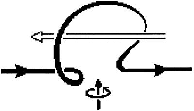
To see the effect of an helical motion on a magnetic field (3, 14), let us consider a local helical motion acting on a flux rope of the mean magnetic field. Supposing that the conductivity of the fluid is high enough, the rope is deformed into a twisted Ω, the loop of the Ω being perpendicular to the plane of the sheet. The current  flowing through the loop of the Ω has a component antiparallel to the original magnetic field in the case of a right-handed helical motion as illustrated by Fig. 1. A left-handed helical motion gives rise to a current parallel to the mean magnetic field. Therefore, such local helical motions randomly appearing in a conducting fluid have the ability to drive an electric current parallel or antiparallel to an applied magnetic field. For a large-scale secondary magnetic field to appear, the turbulence made up of these cyclonic motions can be homogenous and isotropic, but must have helicity, i.e. one kind of helical motion should be more probable than the other one.
Figure 1.
A flux rope twisted into an Ω by a right-handed motion. The loop is accompanied by an electric current antiparallel to the magnetic field (14).
We will start from this picture of the effect of an helical elementary motion on a magnetic field (Fig. 1) to establish our hierarchical model. One of the original features of this model is that the cyclonic turbulence helicity (at different scales; see below) is not constant in time as in most dynamo models, but changes systematically as the large-scale magnetic field evolves.
The Model
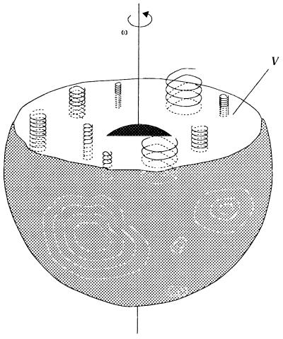
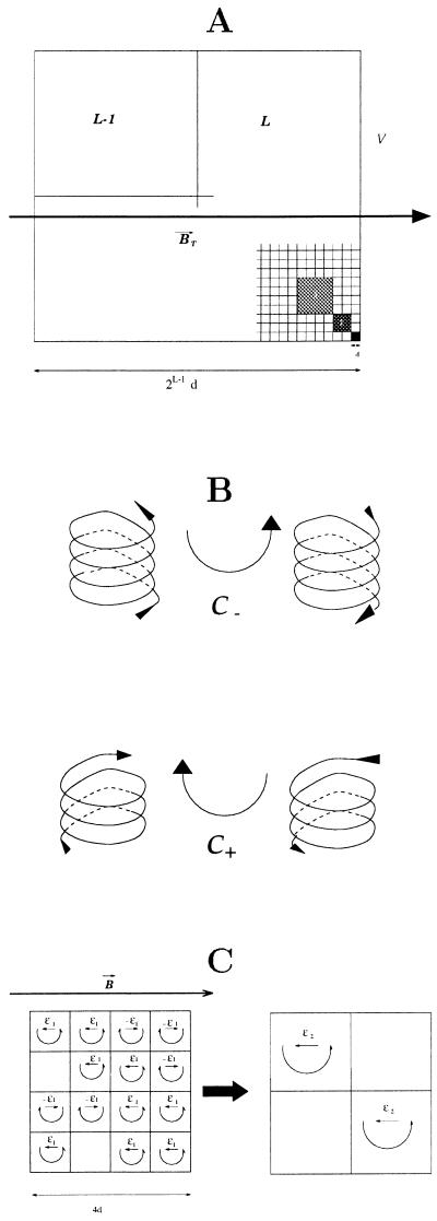
A given volume 𝒱 (Fig. 2) of conducting fluid is represented by a square 𝒟 of side 2ℒ−1 (Fig. 3; we already pointed out the tendency of the flow to be two-dimensional). This volume is pervaded by a uniform magnetic field (e.g.,  This large square represents the ℒth degree of our hierarchical model. The first-degree domains are the squares of side d, the second-degree domains are made of four squares of degree 1, the lth domains are made of four domains of degree (l − 1), and so on until l equals ℒ. Let us now consider a first-degree square, or 1-domain, at time t.
Figure 2.
A representation of our model.
Figure 3.
(A) The hierarchical model. The big square (𝒱) contains 22(ℒ−1) elementary squares of side d. (B) Conventional representation of right-handed and left-handed helical motion (cyclones) used in A and C. (C) Illustration of the scale transfer technique.
This 1-square can contain a left-handed cyclone (of order 1), which we will denote 𝒞+1 (see Fig. 3) with probability p+(1, t).
This 1-square can contain a right-handed cyclone (of order 1), which we will denote 𝒞−1, with probability p−(1, t).
This 1-square can be void with probability [1 − p+(1, t) − p−(1, t)].
A 1-domain is considered as generating an electric current J⃗ antiparallel to  and with an intensity proportional to ℬT if it contains a cyclone 𝒞−1 (right-handed), according to the schema of Fig. 3. In other words, this 1-domain can be viewed as an elementary generator generating the electromotor force
  (this generator is embedded in the conducting fluid). The same holds with a change of sign if the 1-square contains a left-handed cyclone.
Scale Transfer.
The principle of our transfer mechanism, which leads to an inverse cascade in organization, with a step-by-step construction from small to large eddies, can be schematically described as follows. Neighboring cyclones of order 1, 𝒞1, suffer both hydrodynamic and electromagnetic interactions. Basically, cyclones attract each other if they generate parallel electric currents, i.e., have the same helicity, but repel each other if they generate antiparallel current (opposite helicity). Transport by viscosity then will succeed in merging two 𝒞1 cyclones, building an helical motion with the same polarity as the two 𝒞1 motions but with a larger scale, if the two 𝒞1 cyclones rotate in the same sense. The same when considering 𝒞l cyclones located in the l-domains or l-cells, which can form or not a 𝒞l+1 cyclone. These interactions have to be computed taking into account the symmetries imposed by the rapid rotation, gravity, and magnetic field. Merging 1-order cyclones disappear at this scale but are replaced globally by new ones (see below).
We have not yet completed this analysis. Instead we will keep, in this preliminary study, to a phenomenological, somewhat arbitrary, approach. The 2-square made of four 1-squares will be considered as containing a 𝒞2 cyclone (behaving like a  generator) if three of the four 1-squares composing this 2-square contain a 𝒞1 cyclone. The same rule holds for going from the (l − 1) scale to the l scale, up to l = ℒ (Fig. 3). The formula describing this simple scale transfer rule will be given later.
Appearance and Disappearance Coefficients.
The number of 1-squares in 𝒱, however large, is finite. In addition, the cyclonic turbulence varies continuously with time. To simulate this, we consider that an lth square void of any cyclone at time (t − h) can contain a 𝒞+l cyclone at time t, with the probability of appearance α+l (α−l for the appearance of a 𝒞−l cyclone). An lth square containing a 𝒞+l cyclone at time (t − h) can have lost it at time t, with the probability of disappearance β+l (β−l for an lth square containing a 𝒞−l cyclone at time (t − h)). h is the time step; we will discuss the time unit later. Therefore the changes of p+l and p−l from time t to time (t + h) are given by Blanter et al. (30):
 |
5 |
To choose the α± and β± we will rely on phenomenological considerations (note that the probabilities of disappearance cannot always be zero; otherwise the probabilities p+ and p− would never decrease).
We consider in this preliminary study that the poloidal source term in Eq. 4, which describes the behavior of the large-scale fields, only depends on the polarity of the cyclonic turbulence at the highest scale ℒ (scale of 𝒱), which leads to:
 |
6 |
β coefficients. We simply consider that the disappearance coefficients at scale l and time t depend linearly on the probabilities of cyclones, p+ and p−, at the same scale and time:
 |
7 |
These equations represent dissipation. We try in this way to account for the high magnetic diffusivity of the core; the smaller the magnetic structures, the more rapidly they disappear. The disappearance coefficients at first scale, β±(1, t) are indeed large: eddies at this first level have an average live time of five time steps. And β±(l, t) does decrease with l (but large-scale eddies still have a lifetime much shorter than the duration of a reversal). To compensate the high dissipation rate—in particular at first level—high appearance coefficients α are requested. We simulate in this way an active fluctuating turbulence. As Δpℒ, the polarity at the largest scale, is fluctuating, diffusion terms κT𝒯 and κS𝒮 (Eq. 3) play an important part in smoothing the time behavior of the large-scale fields 𝒯 and 𝒮.
α coefficients. For the appearance probabilities, we first consider the three-of-four rule mentioned earlier (Fig. 3). α+(l + 1, t), α−(l + 1, t) then can be derived from p+(l, t), p−(l, t), α+(l, t), α−(l, t), β+(l, t), β−(l, t). Corresponding formula 10 is given in the Appendix. We will call α+a(l, t), α−a(l, t) these coefficients that can be directly derived from the three of four rule (a for arithmetic). Superscript a will be dropped later on, when these apparition coefficients have been modified to take into account the feedback mechanism (see below).
With this rules it will appear that the probabilities p+(l, t), p−(l, t) can be computed from α+(1, 0), α−(1, 0), p+(l, 0), p−(l, 0), l = 1, 2, … , ℒ, 0 being the origin of time, if we know the evolution of the appearance coefficients at the first scale, α+(1, t), α−(1, t). We now will specify the rules defining this time evolution, introducing feedback in the mechanism.
Symmetries and Feedback
In classical αω dynamos the turbulent flow is supposed to have helicity; it is assumed that in a large given volume left-handed cyclones are more probable than right-handed ones, or vice versa. For example, in a model that has been studied by many authors (29; 31–32), the helicity is supposed to vary like cos θ, θ being the colatitude. It is generally argued that Northern and Southern hemispheres are distinguished by the direction of the rotation axis; as a consequence, some quantities, like the average helicity α, which are pseudo-scalar, take opposite signs in the Northern and Southern hemispheres (e.g., ref. 33). It must be noted that there is no definitive argument to support this assumption of lack of mirror symmetry (34).
We are looking for a behavior of our model similar to the behavior of the geomagnetic field, i.e. for (𝒮, 𝒯) solutions of the model presenting long polarity intervals and comparatively rapid reversals. Solutions during polarity intervals will fluctuate around (𝒮0, 𝒯0) or (−𝒮0, −𝒯0). Taking ℛ > 0 and 𝒮0𝒯0 > 0, stationary solutions are obtained for Δpℒ = p+ℒ − p−ℒ > 0. The main ingredient we introduce into our feedback mechanism acting on the evolution of the appearance intensities, α+(1, t), α−(1, t), is thus the following. As soon as 𝒮𝒯 becomes negative, a reaction increases Δα1 = [α+(1, t) − α−(1, t)] to reestablish, after some delay (see below), a large enough positive value of Δpℒ. The dynamo then goes back to one of the pseudo-stationary states (𝒮0, 𝒯0) or (−𝒮0, −𝒯0). This could be interpreted qualitatively as a necessary condition for the dynamo to work (for example, if the flow in the core is driven by compositional convection, the only efficient way to evacuate gravitational energy is through ohmic dissipation). The second important ingredient that is more or less symmetrical with the first one is the tendency during a quiet polarity interval for the helicity to recover mirror symmetry. In other words, the natural, or basic, state of the turbulence in 𝒱 tends to be mirror-symmetric, as long as the magnetic field is maintained. But a certain amount of helicity is needed for this maintenance. The more intense the magnetic field, the more efficient the process of decreasing the helicity at the elementary scale. This leads to the rule:
 |
8 |
With this choice (α+1 + α−1) is maintained at a constant value. The turbulence at the smallest scale always keeps the same activity; only the helicity (α+1 − α−1) evolves slightly (see below).
The decrease of Δα1, in our embedded scales model, generates a decrease of helicity p+(l, t) − p−(l, t) at all scales, after a delay. We also will assume that the appearance coefficients are directly damped, at each scale, proportionally to the energy of the poloidal field 𝒮 (generated by the cyclonic turbulence). We will represent it, as mentioned above, by a modification of the arithmetic coefficients given by formulae 10:
 |
9 |
This represents some kind of saturation mechanism.
Time Constants.
We took in Eq. 3 the diffusive time Θ of 𝒮 as the unit of time (Θ = κ−1). In the following numerical experiments h is taken equal to Θ/30. There is, however, a second time constant in our system, although less well defined. This is the time needed for a change in the appearance rates α+1 and α−1 to have full repercussion on the probabilities at the highest scale, p+ℒ and p−ℒ. In the following numerical experiments this time is of the order of 100h.
Finally there is a third, implicit time scale, identified with the time step h itself. It is assumed that the transfer of the appearance coefficients of scales from 1 to ℒ, as given by rule 10, takes some time to be completed, a time that is precisely the time step h. The choice of h is not critical (the scale transfer acts on the appearance coefficients, or increments α, not on the probabilities p themselves).
Illustrations.
The model displays a variety of behaviors depending on the choice of the parameters. We will illustrate it with three cases corresponding to three choices of λ1, λ2, and λ3, with the other parameters being kept the same. Some initial conditions have to be chosen. We start from a state with no cyclonic turbulence: p+(l, 0) = p−(l, 0) = 0, ∀l. We choose the initial values of the appearance coefficients very close to each other: α+(1, 0) = α−(1, 0) + 10−3, and α−(1, 0) = 0.45. A nonzero field must exist (as usual) at the origin of time to trigger the dynamo mechanism: 𝒯(0) = 0, 𝒮(0) = ɛ, with ɛ small compared with the value 𝒮0 reached during polarity intervals.
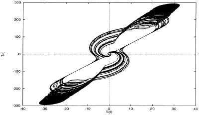
Fig. 4 shows these three realizations of the process [𝒮(t), 𝒯(t)]. 𝒯(t) is the nonnormalized field of Eqs. 2 and 3. Values of the parameters are given in the legend of the figure. Clearly polarity periods, reversals, and excursions are present, as well as a rather schematic periodic secular variation during the polarity intervals. The duration of reversals is of the order of one-fifteenth of the mean duration of polarity periods. Fig. 5 illustrates the process [𝒮(t), 𝒯(t)] in the form of a phase diagram.
Figure 4.
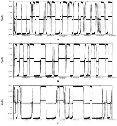
Examples of realizations of the process [𝒮(t), 𝒯(t)]. Values of the parameters are: c0 = 10−2, c1 = 0.9, c2 = 0, μ = 8 × 10⁻⁴, κ =  × 10−2, ζ =
  × 10−2, ω =
  × 10−1. (A) λ1 = 7 × 10⁻¹², λ2 = 8 × 10⁻⁷, λ3 = 45. (B) λ1 = 10−11, λ2 = 3 × 10⁻⁷, λ3 = 50. (C) λ1 = 1.5 × 10⁻¹¹, λ2 = 10−7, λ3 = 60.
Figure 5.
Phase diagram [𝒮(t), 𝒯(t)] corresponding to Fig. 4A.
Following are some qualitative explanations about the way the model works. According to Eq. 8, Δα1 increases slowly. After a delay, Δpℒ increases and passes the critical value ℛ−1. The fields 𝒯 and 𝒮 then start increasing (see eigenvalues of Eq. 3 considered as linear). They would continue to grow exponentially if it were not for the feedback mechanism introduced in Eqs. 8 and 9. Due to this mechanism, oscillations (secular variations) around (𝒮0, 𝒯0) and (−𝒮0, −𝒯0) are observed as long as Δα1 remains positive, and reflect the variable cyclonic state at the higher levels of our hierarchical model. Given the fields’ intensity, the appearance densities decrease. The consequence is a slow decrease of the stationary solutions that keep their secular variations (because Δpℒ > ℛ−1). After a while, however, [a polarity period whose duration depends on the value Δα1 had when the solutions reached (𝒮0, 𝒯0)], Δα1 approaches zero. There is no more transfer of helicity toward the higher scales. Meanwhile Δpℒ decreases. It becomes smaller than the critical value ℛ−1, and the fields start decreasing with their diffusive constant of time. These fields being nonequal to zero, Δα1 continues to decrease and becomes negative (slightly; there is a brief overshoot). Then, after a time delay Δpℒ becomes negative. 𝒯 and 𝒮 would oscillate toward zero if not for the feedback mechanism. At this point, the following evolution depends on the magnitude of the fields 𝒯 and 𝒮 at the time then Δpℒ becomes zero.
If they are large, the feedback (Eq. 8) is strong when 𝒮 has a sign opposite to the one it had before. Then Δpℒ reaches the critical value ℛ−1 quickly enough for 𝒯 to keep the same sign. The dynamo gives an excursion.
If, on the contrary, 𝒯 and 𝒮 are smaller when Δpℒ becomes < 0, they oscillate longer around zero, and 𝒯 can have either sign when Δpℒ has again reached the critical value ℛ−1, due to the feedback mechanism. The field then can return to its former polarity (after an excursion), or reverse.
We already have said that, in the present form of the equations, the stability of the polarity interval (its duration) depends on the value of Δα1 at the time when Δpℒ reaches the critical value ℛ−1.
The behavior of the process, of course, depends on the way we play with λ1, λ2, and λ3. The duration of a reversal is on the order of 2Θ(60h, h = Θ/30). This value seems too large; but Θ may not be the diffusion time for the whole core, but the diffusion time of a large volume of the core, i.e one hemisphere.
Conclusion
The model presented here is no more than a tentative model, and our (limited) attempt to present it as a member of the family of αω dynamos may appear in vain. It could be better to consider by itself the dynamical system ruled by Eqs. 2 to 9. The most interesting feature of the model is that very small variations of the helicity generation at the smallest scale (Δα1 varies only by a few 10−3 all along the process realizations illustrated by Fig. 4) yield major changes at the highest scale, leading to polarity intervals, reversals, excursions, etc. We could, of course, in the same way build dynamos in which 𝒮T were built from 𝒮P through the cyclonic action (∼α2 dynamos although, as we have pointed out, our cyclonic mechanism is different from α effect).
The distribution of durations of examples of Fig. 4 is too narrow compared to the observed ones. It could be improved by changing the rules of Eq. 8. But more physical insight of the model, however, is necessary before arbitrarily changing its parameters.
Appendix
 |
10 |
 |
 |
 |
 |
 |
 |
 |
with
 |
11 |
It is clear that
 |
12 |
References
- 1.Elsasser W M. Phys Rev. 1939;60:876–883. [Google Scholar]
- 2.Takeuchi H, Shimazu Y. J Phys Earth. 1952;2:5–12. [Google Scholar]
- 3.Parker E N. Astrophys J. 1955;122:293–314. [Google Scholar]
- 4.Backus G. Ann Phys. 1958;4:372–447. [Google Scholar]
- 5.Herzenberg A. Philos Trans R Soc London A. 1958;250:543–585. [Google Scholar]
- 6.Malkus W V R. J Geophys Res. 1963;68:2871. [Google Scholar]
- 7.Braginsky S I. Transl Soviet Phys. 1964;20:726–734. [Google Scholar]
- 8.Glatzmaier G A, Roberts P H. Nature (London) 1995;377:203–209. [Google Scholar]
- 9.Cowling T G. R Astron Soc. 1934;94:39–48. [Google Scholar]
- 10.Roberts P H. Lect Appl Math. 1971;14:129–205. [Google Scholar]
- 11.Braginsky S I. Geomagn Aeron. 1978;18:225–231. [Google Scholar]
- 12.Parker E N. Astrophys J. 1955;122:293–314. [Google Scholar]
- 13.Krause F, Steenbeck M. Z Naturforsch. 1967;22:671–675. [Google Scholar]
- 14.Krause F, Rädler K H. Mean-Field Magnetohydrodynamics and Dynamo Theory. Oxford: Pergamon; 1980. [Google Scholar]
- 15.Kraichnan R H. Phys Fluids. 1967;10:1417–1423. [Google Scholar]
- 16.Busse F H. Geophys J R Astron Soc. 1975;42:437–459. [Google Scholar]
- 17.Soward A M. Geophys Astrophys Fluid Dyn. 1977;9:19–74. [Google Scholar]
- 18.Chandrasekhar S. Hydrodynamic and Hydromagnetic Stability. Oxford: Oxford Univ. Press; 1961. [Google Scholar]
- 19.Wilson, K. G. (1979) Sci. Am. 241 (Aug.), 140–157.
- 20.Kadanoff L. Physics. 1966;2:263–373. [Google Scholar]
- 21.Allègre C J, Le Mouël J L, Provost A. Nature (London) 1982;297:47–49. [Google Scholar]
- 22.Allègre C J, Le Mouël J L. Phys Earth Planet Int. 1994;87:85–93. [Google Scholar]
- 23.Allègre C J, Le Mouël J L, Ha Duyen C, Narteau C. Phys Earth Planet Inter. 1995;92:215–233. [Google Scholar]
- 24.Rikitake T. Proc Cambridge Philos Soc. 1958;54:89–105. [Google Scholar]
- 25.Nozières P. Phys Earth Planet Inter. 1978;17:55–74. [Google Scholar]
- 26.Hide R. Geophys Res Lett. 1995;22:1057–1059. [Google Scholar]
- 27.Braginsky S I, Roberts P H. Geophys Astrophys Fluid Dyn. 1987;38:327–349. [Google Scholar]
- 28.Hollerbach R, Barenghi C E, Jones C A. Geophys Astrophys Fluid Dyn. 1992;67:1–25. [Google Scholar]
- 29.Jault D. Geophys Astrophys Fluid Dyn. 1995;79:99–124. [Google Scholar]
- 30.Blanter E M, Shnirman M G, Le Mouël J L, Allègre C J. Phys Earth Planet Int. 1997;99:295–307. [Google Scholar]
- 31.Roberts P H. Philos Trans R Soc London A. 1972;272:663–698. [Google Scholar]
- 32.Barenghi C E, Jones C A. Geophys Astrophys Fluid Dyn. 1991;60:211–243. [Google Scholar]
- 33.Yoshizawa N. Phys Plasmas. 1996;3(10):3604–3613. [Google Scholar]
- 34.Krause F, Steenbeck M. Z Naturforsch. 1960;22:671–675. [Google Scholar]


