Abstract
Bone is an anisotropic structure which can be compared to a composite material. Discontinuities within its microstructure may provide stress concentration sites for crack initiation, but act as a barrier to its propagation. This study looks specifically at the relationship between crack length and propagation in compact bone. Beam-shaped bone samples from sheep radii were prepared and stained with fluorochrome dyes and tested in cyclic fatigue under four-point bending in an INSTRON 1341 servo-hydraulic fatigue-testing machine. Samples were tested at a frequency of 30 Hz and stress range of 100 MPa under load control. Specimens were sectioned transversely using a diamond saw, slides prepared and examined using epifluorescence microscopy. Cracks in transverse sections were classified in terms of their location relative to cement lines surrounding secondary osteons. Mean crack length, crack numerical density and crack surface density were examined. Short microcracks (100 µm or less) were stopped at the cement lines surrounding osteons, microcracks of intermediate length (100–300 µm) were deflected as they hit the cement line, and microcracks that were able to penetrate through cement lines were longer (> 400 µm). These data show that bone microstructure allows the initiation of microcracks but acts as a barrier to crack propagation.
Keywords: cement line, compact bone, fatigue testing, lengths, microcrack, secondary osteon
Introduction
Microdamage in bone occurs in the form of microcracks as a result of everyday cyclical loading activities. These microcracks act as a stimulus for remodelling (Burr et al. 1985; Prendergast & Taylor, 1994; Verborgt et al. 2000; Lee et al. 2002). This microdamage is repaired by ‘targeted’ remodelling to the sites of damage. Stress fractures are fractures resulting from damage accumulation at loading above some high threshold, and are seen in military recruits, athletes, ballet dancers and footballers (Burr, 1997; Milgrom et al. 1985, 2000, 2003). Approximately 10% of injuries seen in sports medicine centres are stress fractures and those of the lower limbs comprise about 95% of the cases (Brunet et al. 1990; Johnson et al. 1994). If, by contrast, damage accumulates at ‘normal’ rates but the bone's repair mechanism is deficient, fragility fractures may result, which occurs commonly in ageing bone (Schaffler et al. 1994, 1995). Fragility fractures are fractures occurring in response to minor trauma that in healthy adults would not lead to fracture (Heaney, 1993). Such fractures are common in osteoporotic patients.
It has been shown that the fatigue process, damage that occurs due to cyclical loads imposed for a certain period of time as in walking, affects the mechanical properties of cortical bone by reducing its stiffness and fracture resistance (Carter & Hayes, 1977; Schaffler et al. 1989; Boyce et al. 1996). If the stiffness loss is less than 20% of its original value, the damage is usually well tolerated and does not significantly compromise the bone tissue properties. The lamellar structure of bone and repair through remodelling may control the growth of microdamage (Martin et al. 1998).
The mechanical properties of bone are strongly affected by factors such as porosity, mineralization, collagen fibre orientation, diameter and spacing, and other aspects of histological structure. These factors have a positive influence on crack initiation but negative influence on their growth (Martin & Burr, 1989). Bone microstructure has a high resistance to fatigue crack growth by keeping cracks small and running in harmless directions, parallel to the line of action of the loads applied to it, at least long enough in vivo for the cracks to be repaired.
Human cortical bone is characterized as primary and secondary. Primary bone is laid down on existing bone surfaces during growth, e.g. circumferential lamellar bone beneath the periosteal surface. Blood vessels within the primary bone are surrounded by few circular lamellae termed concentric lamellae and are known as primary osteons. These primary osteons are smaller, shorter, fewer in number and have no cement line boundaries as compared with secondary osteons in secondary compact bone (Atkinson & Hallsworth, 1982).
Secondary compact bone results from the resorption of existing bone and its replacement by new lamellar bone (remodelling). Secondary compact bone may be compared to a fibre composite material. Secondary osteons (hereafter referred to simply as ‘osteons’) form a basic structural unit of human compact bone. They are round to ellipsoidal in transverse section, vary from 100 to 400 µm in diameter and can be 1–2 mm long (Cohen & Harris, 1958; Mohsin et al. 2002). Each osteon consists of a central Haversian canal containing the neurovascular bundle, surrounded by concentric lamellae, and is permeated with lacunae and canaliculi for osteocytes and their processes. It is bounded by a cement line which separates one osteon from neighbouring osteons and lamellar bone.
These cement lines have been described as thin lines of discontinuity formed by the activity of a basic multicellular unit (BMU) on resorbed bone surfaces, distinguishing primary from secondary bone and are also known as reversal or resorption lines (Frost, 1966). These are about 1–2 µm thick and have little or no collagen (Frasca, 1981). They are differently mineralized from the surrounding bone matrix and contain only 85–90% of the calcium and phosphorus found in adjacent matrix. The sulphur content of cement lines is markedly greater than that of lamellar bone and it has also been suggested that substantial amounts of sulphated mucosubstances may be present (Schaffler et al. 1987). Although the exact structure and function of these cement lines are not known, they are thought to be responsible for significant stiffness variations in bone (Burr et al. 1988). We were unable to confirm whether these cement lines correspond to regions of mechanical weakness (Frasca et al. 1977) or toughness in bone. Burr et al. (1988) showed that the presence of cement lines could increase the static toughness of bone by preventing deleterious crack growth and ultimately improve its fatigue properties.
Compact bone is essentially lamellar. Apart from the circumferential and concentric discussed above, there are ‘interstitial’ lamellae between osteons which are mainly fragmentary remains of older osteons or primary bone tissue. All lamellae contain collagen fibres. Many investigators have studied the orientation of collagen fibres in human secondary osteons and almost all have reported variations in orientation within lamellae (Smith, 1960; Cooper et al. 1966; Ascenzi & Bonucci, 1967, 1976; Boyde, 1972). In secondary compact bone it might therefore be expected that cracks would tend to remain small and follow the fibres instead of propagating across osteons.
It has been shown (Rho et al. 1999, 2002) that mechanical properties vary between osteons and adjacent interstitial bone and even between lamellae within the same osteons. The interstitial bone is stiffer than osteonal bone and it is easier to initiate cracks in stiffer tissues. Softer osteons tend to direct cracks present in the interstitial lamellae towards them, thereby increasing the likelihood of crack-stopping mechanisms such as cement line debonding (Burr et al. 1988; Guo et al. 1998). These findings have important implications for the mechanical contribution of individual osteons to bone biomechanics.
The interaction of microcracks with microstructure of bone has been studied by numerous researchers (Martin & Burr, 1989; Taylor & Prendergast, 1997; Taylor, 1998a,b). Zioupos & Currey (1994) showed that microcracks in bone did interact with the microstructure of the bone and that the grain of the bone did not allow microcracks to travel in straight lines. They hypothesized that the presence of lamellae influenced the process by which microcracks coalesced but that vascular or other naturally occurring cavities did not initiate microcracking and appeared to deflect microcracks. Schaffler et al. (1994) used back-scattered electron microscopy on fuchsin-stained sections of human rib to show that features of the bone matrix ultrastructure, such as the collagen fibre – bone mineral relationship, play a key role in minimizing the formation of larger detrimental cracks, whilst encouraging the formation of numerous small cracks which do not propagate as readily to failure.
A number of authors have mentioned the possibility of a microstructural barrier effect in bone (Akkus & Rimnac, 2000; O'Brien et al. 2003), whereby the critical stage in the fatigue process is not the initiation of cracks but their propagation beyond microstructural sizes. Evans & Riolo (1970) showed that the presence of an increased number of osteons was directly related to the fatigue life of a bone whereas, conversely, when more interstitial lamellae were present, the fatigue life was considerably shorter. This suggests that crack propagation is inhibited by increased numbers of osteons and supports the idea that osteons with compliant cement lines have significant mechanical effects in bone (Burr et al. 1988). Lakes et al. (1990) noted that osteonal microstructure played an important role in the fracture process for short cracks (250–500 µm). Boyce et al. (1998) showed experimentally that microcracks developed in the interstitial tissue regions and stopped at the osteonal boundaries, and Schaffler et al. (1995) added quantitative data to this hypothesis, suggesting that 80–90% of all microcracks in cortical bone are found in the interstitial matrix between osteons.
O'Brien et al. (2005) showed that, in bovine bone, the microstructural barrier effect is dependent on the crack length at the time of encountering an osteon. For the vast majority of cracks, osteons act as barriers to growth, but for a small number of cracks that are long enough to break through the cement line, an osteon may actually act as a weakness in the bone and encourage further propagation. This study looked at the process by which microcracks interact with ovine bone microstructure by studying total crack length at the time of encountering the cement line surrounding an osteon and analysed whether this influences the crack's ability to continue to grow.
Materials and methods
Adult sheep radii were selected for this project from a previous study (Lee et al. 2002). The cortical bone of sheep is similar to other species of large domestic mammals. Although the bone of young sheep is plexiform, Haversian remodelling also takes place in adult sheep, notably in the diaphysis of the radius (Newman et al. 1995). Therefore, radii from eight adult mature sheep were selected.
Eight bone specimens were cut from the medial aspect of the diaphysis of each radius along the longitudinal axis using a band saw. Beam-shaped specimens were prepared using a diamond saw and milling machine. Each specimen was 40 mm long and had a width and a height corresponding to the minimal thickness of the cortex (mean width and height was 7 × 2.6 mm). The specimens were wrapped in cling film and stored at −20 °C prior to testing. On the day of testing, specimens were thawed in de-ionizd water for 1 h, and stained with 0.0005 m alizarin in a desiccator under vacuum (6.66 kPa) for 16 h to label pre-existing damage (O'Brien et al. 2002). The specimens were then placed in a bath of 0.0005 m calcein or xylenol orange and tested in cyclical fatigue under four-point bending in an INSTRON 1341 servo-hydraulic testing machine. The samples were tested under load control at a frequency of 30 Hz until failure occurred. The stress range used was 11–110 MPa, i.e. the R stress ratio between minimum and maximum stress was 0.1. All tests were carried out at room temperature. Specimens were kept wet during all stages of machining and testing.
Following testing the specimens were dehydrated through a graded series of alcohol (80, 90, 95 and 100% each for 1 day) and embedded in a styrene-based polyster casting resin ‘Kleer set resin™’ (Metprep Ltd) at room temperature. The specimens were sectioned transversely, avoiding the main fractured surface, using a diamond saw (Struers Miniton). The slides were viewed under transmitted light and epifluorescence microscopy. The cross-sectional area of the sections was measured and microcracks were identified and analysed using established criteria (Lee et al. 1998, 2000; O'Brien et al. 2002). Images of microcracks were captured and transferred to a PC using a CCD colour video camera. Measurements were made using ‘Lucia Measurement version 4.71’.
The percentage of osteonal and interstitial bone in each of the specimens was measured from five slides per specimen. Osteon density was calculated by dividing the average number of osteons by average area.
Crack data were expressed in terms of crack numerical density: the number of cracks occurring per mm2 (Cr.Dn); crack surface density: total length (µm) of crack per mm2 (Cr.S.Dn) and mean crack length (Cr.Le) (µm). Microcracks were divided into seven different categories based on their relationship with cement lines and secondary osteons (Table 1). Data were analysed using the software program ‘Sigmastat 3.0’. Kruskal–Wallis one-way analysis of variance (anova) on ranks was performed to assess differences throughout followed by an all pair-wise multiple comparison procedure (Dunn's method) in case of a significant overall effect. Differences between individual groups were analysed using the Mann–Whitney rank sum test. The level of significance was set at P < 0.05.
Table 1.
Characterization of microcracks into seven categories
| (i) | Microcracks that did not hit an osteon |
| (ii) | Microcracks stopped outright when they encountered a cement line |
| (iii) | Microcracks that encountered a cement line and were deflected around the osteon |
| (iv) | Microcracks that encountered a cement line and penetrated the osteon |
| (v) | Microcracks that encountered osteons at both crack tips and stopped |
| (vi) | Osteonal microcracks were found completely within the osteon |
| (vii) | Pre-existing microcracks were present prior to fatigue testing |
Results
The mean (±SD) number of cycles to failure for the four-point bend tests was 74 529 ± 38 008. Histological analysis showed that most of the specimens had mixed histology, with fibrolamellar bone towards the surface of the specimens and osteonal bone mostly in the centre. The results showed that, on average, 49% of the bone was osteonal and 51% was interstitial and fibrolamellar. Osteon density ranged between 15 and 26 mm2 (mean ± SD: 20 ± 4.22 mm2).
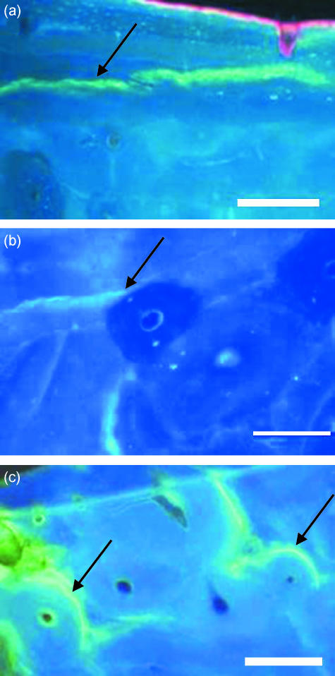
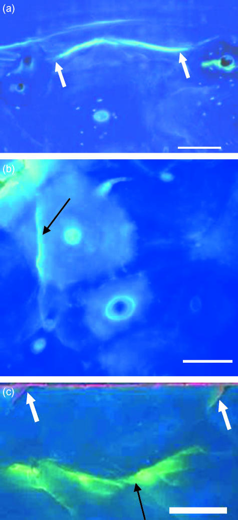
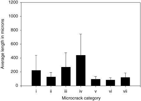
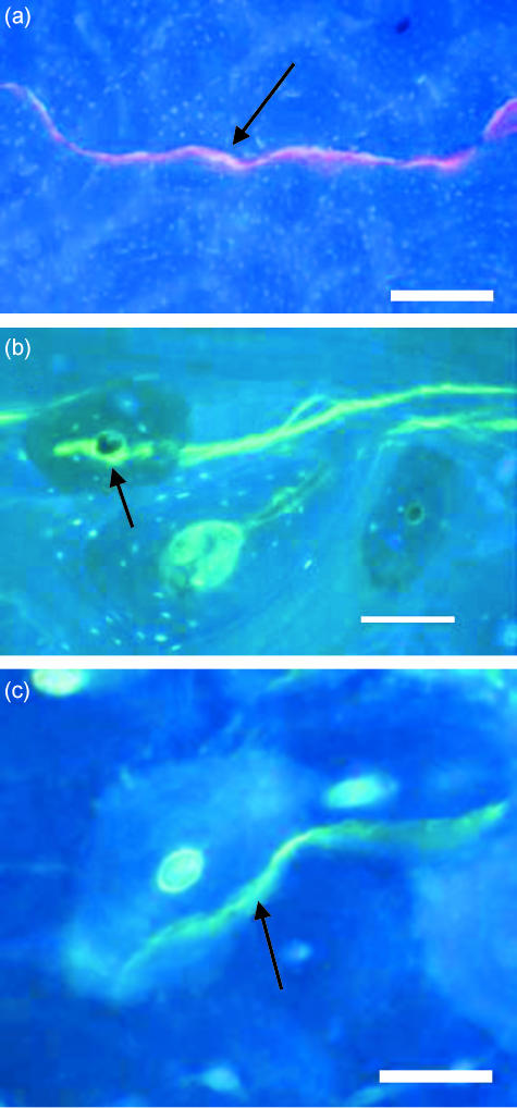
Examples of the different categories of microcracks labelled with fluorochrome dyes are shown in Figs 1–3. Figure 4 shows the mean length for each category. Statistical analysis showed that crack length at the time of encountering an osteon significantly affected its ability to propagate (P < 0.05). All the individual groups showed statistically significant differences (P < 0.05) except category (v) vs. (ii, vi and vii), and category (vi) vs. (vii).
Fig. 1.
Examples of different categories of microcracks, stained with calcein which fluoresces green, shown in transverse sections of bone viewed under UV light (365 nm): (a) microcrack that did not hit any osteon (arrow), (b) microcrack that hit an osteon and stopped outright (arrow), (c) microcracks that hit an osteon and were deflected around the cement line (arrow). Scale bar, 100 µm.
Fig. 3.
Transverse sections of bone viewed with UV epifluorescence (λ = 365 nm) showing (a) a microcrack stained with calcein limited by osteons at both ends as shown by arrows, (b) microcrack that lies totally within an osteon (arrow), (c) alizarin (fluorescing red) has labelled the outer surface of the specimen. Pre-existing microcracks are shown (white arrows). Calcein-labelled microcrack (black arrow) that did not hit any osteon is also visible. Scale bar, 100 µm.
Fig. 4.
Average length for all types of microcrack. (i) Did not hit an osteon. (ii) Hit an osteon and stopped. (iii) Hit an osteon and was deflected. (iv) Hit an osteon and penetrated the cement line. (v) Hit an osteon at both ends. (vi) Osteonal. (vii) Pre-existing. Error bars in the figure represent standard deviation. Sample size for category (i) microcracks n = 312, similarly n (ii) = 53, n (iii) = 47, n (iv) = 69, n (v) = 35, n (vi) = 54, n (vii) = 7. Statistical analysis indicated that crack length at the time of encountering an osteon significantly affected its ability to propagate. Statistical analysis showed that microcracks that penetrated the cement line were significantly longer (P < 0.05) than those of other groups. All the individual groups showed statistically significant difference (P < 0.05) except category (v) vs. (ii, vi and vii), and category (vi) vs. (vii).
Category (i) includes those cracks that did not encounter osteons (Fig. 1a). These grew to an average length of 220 ± 218 µm before halting. Category (ii), cracks that stopped growing outright when they encountered a cement line surrounding an osteon (Fig. 1b), had a mean length of 127 ± 66 µm. Category (iii), cracks that propagated to an osteonal cement line and were deflected into it and around the osteon (Fig. 1c), had a mean length 268 ± 206 µm. Category (iv), cracks that did manage to penetrate the cement lines surrounding osteons, were significantly longer (P < 0.05) than all the other categories (440 ± 304 µm). Such microcracks may hit the Haversian canal and pass right through it to the Haversian canals of subsequent osteons (Fig. 2a), or hit the Haversian canal and be deflected (Fig. 2b) or be deflected on entering the osteon and avoid the canal (Fig. 2c). Category (v), cracks that encountered osteons at both tips (Fig. 3a), generally stopped growing outright at both ends as they encountered cement lines and had an average length of 94 ± 39 µm. Category (vi), microcracks found completely within osteons (Fig. 3b), had an average length of 82 ± 32 µm. Pre-existing microcracks (Fig. 3c) in category (vii) were 119 ± 66 µm in length.
Fig. 2.
Transverse section of bone viewed with UV epifluorescence (λ = 365 nm) showing different paths taken by microcracks (black arrows) after they hit an osteon and penetrated through the cement line: (a) a microcrack (stained with xylenol orange) passes through the Haversian canals of subsequent osteons, (b) a microcrack (stained with calcein) deflected (arrow) as it hits the Haversian canal within an osteon, (c) a calcein-stained microcrack (arrow) did not hit the Haversian canal within an osteon. Scale bar, 100 µm.
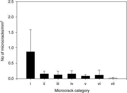
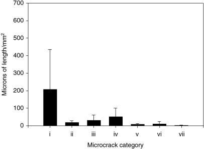
Results for crack numerical density (Fig. 5) showed that the majority of cracks did not hit osteons (P < 0.05). Pre-existing cracks (Fig. 3c) were located close to the surface, did not propagate and were fewest in number (Fig. 5). Results for crack surface density (Fig. 6) showed that the level of damage was greatest in interstitial and fibrolamellar bone.
Fig. 5.
Crack numerical densities for all type of microcracks. (i) Did not hit an osteon. (ii) Hit an osteon and were halted. (iii) Hit an osteon and were deflected. (iv) Hit an osteon and penetrated the cement line. (v) Hit an osteon at both ends. (vi) Osteonal. (vii) Pre-existing. Error bars represent standard deviation. Kruskal–Wallis one-way analysis of variance on ranks showed that the number of microcracks that did not hit any osteons was highest, P < 0.05.
Fig. 6.
Crack surface densities for each type of microcrack. (i) Did not hit an osteon. (ii) Hit an osteon and were halted. (iii) Hit an osteon and were deflected. (iv) Hit an osteon and penetrated the cement line. (v) Hit an osteon at both ends. (vi) Osteonal. (vii) Pre-existing. Error bars represent standard deviation. Kruskal–Wallis one-way analysis of variance on ranks showed highest level of damage in interstitial and fibrolamellar bone. P < 0.05.
Discussion
The interaction of microcracks with the microstructure of bone was analysed in terms of different patterns of crack growth in relation to secondary osteons, the influence of length of a microcrack on its ability to propagate through bone microstructure and the preferred sites for crack accumulation.
Up to a critical length, crack growth requires energy input into the material, but beyond this point the release of strain energy from the material causes cracks to spread increasingly faster, leading to failure. Cracks shorter than the critical length are stable and will not normally extend, whereas those longer than the critical length are self-propagating and very dangerous (Lee, 2003; Taylor & Lee, 2003).
Any increase in the length of the crack results in an increase in the total surface energy. Short microcracks are less energetic and stop as they hit an osteon. When microcracks of intermediate length (average length 268 ± 206 µm) hit an osteon, they are deflected around cement lines towards a path of least resistance. They may not possess sufficient surface energy to pass through cement lines but have still enough to allow the crack to propagate into interstititial lamellae for some distance. Crack deflection at the osteon–matrix interface serves the purpose of energy absorption and re-orientation so that the applied stresses no longer spread apart the crack tip (Martin & Burr, 1989). Microcracks that passed right through the cement lines had longer average lengths. On entering the osteon such microcracks either propagate into neighbouring osteons without hitting the Haversian canal (by chance) and/or they may hit the Haversian canal and be deflected into subsequent neighbouring osteons, as was also observed by Zioupos & Currey (1994).
Microcracks did not hit osteons in areas of low osteonal density. Microcracks in such areas were found either in older, more brittle, interstitial lamellae or were present close to the surface and in the circumferential lamellae. These microcracks reached quite considerable lengths (average 220 ± 218 µm) and stopped without hitting osteons. This suggests the presence of another mechanism, in addition to cement lines, to halt such microcracks, as proposed by O'Brien et al. (2005). It may be possible that they may dissipate all their energy as they run between lamellae, due to change in the direction of fibres, or at lamellar interfaces which they encounter.
By calculating the crack numerical densities and percentages, this study was able to determine the general trends for accumulation of microdamage. The majority of microcracks observed did not hit any osteons and were found in interstitial bone. This finding is consistent with previous studies (Schaffler et al. 1994; Jepsen et al. 1999; O'Brien et al. 2003, 2005). Microcracks that actually penetrated the cement lines were few in number. Pre-existing microcracks were fewest in number, endorsing the machining technique used. Crack surface density for each category of microcracks was also measured to quantify the level of microdamage. Higher values were observed for cracks formed in interstitial bone. The structure of Haversian bone is such as to arrest the majority of microcracks and these smaller microcracks are not deleterious as they are repaired through remodelling. It has been hypothesized in previous studies that the ability of bone to form many tiny microcracks (as opposed to fewer large cracks) would absorb energy and be less likely to weaken the bone (Reilly & Currey, 2000).
The presence of porosities, lamellar interfaces and cement lines in compact bone tends to arrest smaller microcracks by absorbing their energy and deflecting them in a harmless direction. The presence of these microstructural features increases fracture toughness while at the same time minimizing damage to neural and vascular structures within the Haversian canal (Martin & Burr, 1989). Only a small number of microcracks passed right through the Haversian canals of adjacent osteons. For such long microcracks, osteons may actually act as a weakness in bone and encourage further propagation and eventually failure (O'Brien et al. 2005). Thus, the length of a microcrack determines the way it behaves in bone.
Taylor (1998a) developed a theoretical model to show how information on the fatigue behaviour of microcracks can be obtained by an analysis of stiffness changes measured during cyclical loading. Taylor (1998b) took the spacing of the microstructural barriers to be 100 µm and assumed an elliptical crack shape (Taylor & Lee, 1998). This is consistent with the results presented here that cracks which encountered osteons at both tips had an average length of 94 ± 39 µm. The initiation and growth of microcracks in compact bone occurs rather easily as they tend to form in weaker regions of the bone matrix. The rate of crack growth decreases rapidly as crack length increases in the range of 0–100 µm due to the presence of microstructural features which cause growth to slow and in some cases to stop completely. If growth continues, the microcrack eventually becomes a macrocrack and its growth rate is determined by the average resistance of the material.
This study shows that osteons bounded by cement lines have a definite role in the fatigue behaviour of bone. The microstructure of compact bone causes smaller cracks to be trapped or deflected at osteonal boundaries, allowing only a small number of cracks with longer lengths to penetrate cement lines.
Acknowledgments
We wish to thank Dr Anthony Staines for the statistics part of the project and Mr Peter O'Reilly for technical assistance. Financial support from Royal College of Surgeons in Ireland is gratefully acknowledged.
References
- Akkus O, Rimnac CM. Cortical bone tissue resists fatigue fracture by deceleration and arrest of microcrack growth. J Biomech. 2000;34:757–764. doi: 10.1016/s0021-9290(01)00025-2. [DOI] [PubMed] [Google Scholar]
- Ascenzi A, Bonucci E. The tensile properties of single osteons. Anat Record. 1967;158:375–386. doi: 10.1002/ar.1091580403. [DOI] [PubMed] [Google Scholar]
- Ascenzi A, Bonucci E. Mechanical similarities between alternate osteon and cross-ply laminates. J Biomech. 1976;9:65–67. doi: 10.1016/0021-9290(76)90124-x. [DOI] [PubMed] [Google Scholar]
- Atkinson PJ, Hallsworth AS. The spatial structure of bone. In: Harrison RJ, Navaratum V, editors. Progress in Anatomy. Cambridge: Cambridge University Press; 1982. pp. 179–199. [Google Scholar]
- Boyce TM, Fyhrie DP, Brodie FR, Schaffler MB. Residual mechanical properties of human cortical bone following fatigue loading. In: Fyhrie D, Gregor R, editors. 20th Annual Meeting of the American Society of Biomechanics, Atlanta. Atlanta, GA: Georgia Institute of Technology; pp. 17–19. [Google Scholar]
- Boyce TM, Fyhrie DP, Glotkowski MC, Radin EL, Schaffler MB. Damage type and strain mode associations in human compact bone bending fatigue. J Orthop Res. 1998;16:322–329. doi: 10.1002/jor.1100160308. [DOI] [PubMed] [Google Scholar]
- Boyde A. Scanning electron microscope studies of bone. In: Bourne GH, editor. The Biochemistry and Physiology of Bone. New York: Academic Press; 1972. pp. 259–310. [Google Scholar]
- Brunet ME, Cook SD, Brinker MR. A survey of running injuries in 1505 competitive and recreational runners. J Sports Med Phys Fit. 1990;30:307–315. [PubMed] [Google Scholar]
- Burr DB, Martin RB, Schaffler MB, Radin EL. Bone remodelling in response to in vivo fatigue microdamage. J Biomech. 1985;18:189–200. doi: 10.1016/0021-9290(85)90204-0. [DOI] [PubMed] [Google Scholar]
- Burr DB, Schaffler MB, Fredrickson RG. Composition of the cement line and its possible mechanical role as a local interface in human compact bone. J Biomech. 1988;21:939–945. doi: 10.1016/0021-9290(88)90132-7. [DOI] [PubMed] [Google Scholar]
- Burr DB. Bone, exercise and stress fracture. Exerc Sport Sci Rev. 1997;25:171–194. [PubMed] [Google Scholar]
- Carter DR, Hayes WC. Compact bone fatigue damage: a microscopic examination. Clin Orthop Rel Res. 1977;127:265–274. [PubMed] [Google Scholar]
- Cohen J, Harris WH. The three-dimensional anatomy of Haversian systems. J Bone Joint Surg. 1958;40:419–434. A. [PubMed] [Google Scholar]
- Cooper RR, Milgram JW, Robinson RA. Morphology of the osteon. J Bone Joint Surg. 1966;48A:1239–1271. [PubMed] [Google Scholar]
- Evans FG, Riolo ML. Relations between the fatigue life and histology of adult human cortical bone. J Bone Joint Surg. 1970;52:1579–1586. [PubMed] [Google Scholar]
- Frasca P, Harper RA, Katz JL. Collagen fiber orientations in human secondary osteons. Acta Anat. 1977;98:1–13. doi: 10.1159/000144772. [DOI] [PubMed] [Google Scholar]
- Frasca P. Scanning electron microscopy studies of ground substance in the cement lines, resting lines, hypercalcified rings and reversal lines of human cortical bone. Acta Anat. 1981;109:115–121. doi: 10.1159/000145373. [DOI] [PubMed] [Google Scholar]
- Frost HM. The Bone Dynamics in Osteoporosis and Osteomalacia. Springfield, IL: Thomas; 1966. [Google Scholar]
- Guo XE, Liang LC, Goldstein SA. Micromechanics of osteonal cortical bone fractures. J Biomech Eng. 1998;120:112–117. doi: 10.1115/1.2834290. [DOI] [PubMed] [Google Scholar]
- Heaney RP. Is there a role for bone quality in fragility fractures? Calcif Tissue Int. 1993;53(Suppl. 1):S3–S6. doi: 10.1007/BF01673394. [DOI] [PubMed] [Google Scholar]
- Jepsen KJ, Davy DT, Krzypow DJ. The role of the lamellar interface during torsional yielding of human cortical bone. J Biomech. 1999;32:303–310. doi: 10.1016/s0021-9290(98)00179-1. [DOI] [PubMed] [Google Scholar]
- Johnson AW, Weiss CB, Jr, Wheeler DL. Stress fractures of the femoral shaft in athletes more common than expected. A new clinical test. Am J Sports Med. 1994;22:248–256. doi: 10.1177/036354659402200216. [DOI] [PubMed] [Google Scholar]
- Lakes RS, Nakamura S, Behiri JC. Fracture mechanics of bone with short cracks. J Biomech. 1990;23:967–975. doi: 10.1016/0021-9290(90)90311-p. [DOI] [PubMed] [Google Scholar]
- Lee TC, Myers ER, Hayes WC. Fluorescence-aided detection of microdamage in compact bone. J Anat. 1998;193:179–184. doi: 10.1046/j.1469-7580.1998.19320179.x. [DOI] [PMC free article] [PubMed] [Google Scholar]
- Lee TC, Arthur TL, Gibson LJ, Hayes WC. Sequential labelling of microdamage in bone using chelating agents. J Orthop Res. 2000;18:322–325. doi: 10.1002/jor.1100180222. [DOI] [PubMed] [Google Scholar]
- Lee TC, Staines A, Taylor D. Bone adaptation to load: microdamage as a stimulus for bone remodelling. J Anat. 2002;201:437–446. doi: 10.1046/j.1469-7580.2002.00123.x. [DOI] [PMC free article] [PubMed] [Google Scholar]
- Lee TC. Microdamage in osteoporosis, bone quality and remodelling. J Anat. 2003;203:159. doi: 10.1046/j.1469-7580.2003.00194.x. [DOI] [PMC free article] [PubMed] [Google Scholar]
- Martin RB, Burr DB. Structure, Function and Adaptation of Compact Bone. New York: Raven Press; 1989. [Google Scholar]
- Martin RB, Burr DB, Sharkey NA. Skeletal Tissue Mechanics. New York: Springer; 1998. [Google Scholar]
- Milgrom C, Giladi M, Stein M, et al. Stress fractures in military recruits. A prospective study showing an unusually high incidence. J Bone Joint Surg Br. 1985;67:732–735. doi: 10.1302/0301-620X.67B5.4055871. [DOI] [PubMed] [Google Scholar]
- Milgrom C, Finestone A, Levi Y, et al. Do high impact exercises produce higher tibial strains than running? Br J Sports Med. 2000;34:195–199. doi: 10.1136/bjsm.34.3.195. [DOI] [PMC free article] [PubMed] [Google Scholar]
- Milgrom C, Finestone A, Segev S, Olin C, Arndt T, Ekenman I. Are overground or treadmill runners more likely to sustain tibial stress fracture? Br J Sports Med. 2003;37:160–163. doi: 10.1136/bjsm.37.2.160. [DOI] [PMC free article] [PubMed] [Google Scholar]
- Mohsin S, Taylor D, Lee TC. Three-dimensional reconstruction of Haversian system in ovine compact bone. Eur J Morph. 2002;40:309–315. doi: 10.1076/ejom.40.5.309.28901. [DOI] [PubMed] [Google Scholar]
- Newman E, Turner AS, Wark JD. The potential of sheep for the study of osteopenia: current status and comparison with other animal models. Bone. 1995;16:277–284. doi: 10.1016/8756-3282(95)00026-a. [DOI] [PubMed] [Google Scholar]
- O'Brien FJ, Taylor D, Lee TC. An improved labelling technique for monitoring microcrack growth in compact bone. J Biomech. 2002;35:523–526. doi: 10.1016/s0021-9290(01)00200-7. [DOI] [PubMed] [Google Scholar]
- O'Brien FJ, Taylor D, Lee TC. Microcrack accumulation at different intervals during fatigue testing of compact bone. J Biomech. 2003;36:973–980. doi: 10.1016/s0021-9290(03)00066-6. [DOI] [PubMed] [Google Scholar]
- O'Brien FJ, Taylor D, Lee TC. The effect of bone microstructure on the initiation and growth of microcracks. J Orthop Res. 2005;23:475–480. doi: 10.1016/j.orthres.2004.08.005. [DOI] [PubMed] [Google Scholar]
- Prendergast PJ, Taylor D. Prediction of bone adaptation using damage accumulation. J Biomech. 1994;27:1067–1076. doi: 10.1016/0021-9290(94)90223-2. [DOI] [PubMed] [Google Scholar]
- Reilly GC, Currey JD. The effects of damage and microcracking on the impact strength of bone. J Biomech. 2000;33:337–343. doi: 10.1016/s0021-9290(99)00167-0. [DOI] [PubMed] [Google Scholar]
- Rho JY, Zioupos P, Currey JD, Pharr GM. Variations in the individual thick lamellar properties within osteons by nanoindentation. Bone. 1999;25:295–300. doi: 10.1016/s8756-3282(99)00163-5. [DOI] [PubMed] [Google Scholar]
- Rho JY, Zioupos P, Currey D, Pharr GM. Microstructural elasticity and regional heterogeneity in human femoral bone of various ages examined by nano-indentation. J Biomech. 2002;35:189–198. doi: 10.1016/s0021-9290(01)00199-3. [DOI] [PubMed] [Google Scholar]
- Schaffler MB, Burr DB, Fredrickson RG. Morphology of the osteonal cement line in human bone. Anat Record. 1987;217:223–228. doi: 10.1002/ar.1092170302. [DOI] [PubMed] [Google Scholar]
- Schaffler MB, Radin EL, Burr DB. Mechanical and morphological effects of strain rate on fatigue in compact bone. Bone. 1989;10:207–214. doi: 10.1016/8756-3282(89)90055-0. [DOI] [PubMed] [Google Scholar]
- Schaffler MB, Pitchford W, Choi K, Riddle JM. Examination of compact bone microdamage using back-scattered electron microscopy. Bone. 1994;15:483–488. doi: 10.1016/8756-3282(94)90271-2. [DOI] [PubMed] [Google Scholar]
- Schaffler MB, Choi K, Milgrom C. Aging and matrix microdamage accumulation in human compact bone. Bone. 1995;17:521–525. doi: 10.1016/8756-3282(95)00370-3. [DOI] [PubMed] [Google Scholar]
- Smith JW. The arrangement of collagen fibres in human secondary osteon. J Bone Joint Surg. 1960;42B:588–605. doi: 10.1302/0301-620X.42B3.588. [DOI] [PubMed] [Google Scholar]
- Taylor D, Prendergast PJ. A model for fatigue crack propagation and remodelling in compact bone. J Eng In Med. 1997;211:369–375. doi: 10.1243/0954411971534494. [DOI] [PubMed] [Google Scholar]
- Taylor D. Microcrack growth parameters for compact bone deduced from stiffness variations. J Biomech. 1998a;31:587–592. doi: 10.1016/s0021-9290(98)00050-5. [DOI] [PubMed] [Google Scholar]
- Taylor D. Fatigue of bone and bones: an analysis based on stressed. J Orthop Res. 1998b;16:163–169. doi: 10.1002/jor.1100160203. [DOI] [PubMed] [Google Scholar]
- Taylor D, Lee TC. Measuring the shape and size of microcracks in bone. J Biomech. 1998;31:1177–1180. doi: 10.1016/s0021-9290(98)00133-x. [DOI] [PubMed] [Google Scholar]
- Taylor D, Lee TC. Microdamage and mechanical behaviour: predicting failure and remodelling in compact bone. J Anat. 2003;203:203–211. doi: 10.1046/j.1469-7580.2003.00194.x. [DOI] [PMC free article] [PubMed] [Google Scholar]
- Verborgt O, Gibson GJ, Schaffler MB. Loss of osteocyte integrity in association with microdamage and bone remodelling after fatigue in vivo. J Bone Miner Res. 2000;15:60–67. doi: 10.1359/jbmr.2000.15.1.60. [DOI] [PubMed] [Google Scholar]
- Zioupos P, Currey JD. The extent of microcracking and the morphology of microcracks in damaged Bone. J Mat Sci. 1994;29:978–986. [Google Scholar]


