Abstract
Conventional radiography only provides a measure of the X-ray attenuation caused by an object; thus, it is insensitive to other inherent informative effects, such as refraction. Furthermore, conventional radiographs are degraded by X-ray scatter that can obscure important details of the object being imaged. The novel X-ray technology diffraction-enhanced imaging (DEI) has recently allowed the visualization of nearly scatter-free images displaying both attenuation and refraction properties. A new method termed multiple-image radiography (MIR) is a significant improvement over DEI, corrects errors in DEI, is more robust to noise and produces an additional image that is entirely new to medical imaging. This new image, which portrays ultra-small-angle X-ray scattering (USAXS) conveys the presence of microstructure in the object, thus differentiating homogeneous tissues from tissues that are irregular on a scale of micrometres. The aim of this study was to examine the use of MIR for evaluation of soft tissue, and in particular to conduct a preliminary investigation of the USAXS image, which has not previously been used in tissue imaging.
Keywords: diffraction enhanced imaging, multiple image radiography, soft-tissue radiography
Introduction
Conventional radiography only provides a measure of the X-ray attenuation caused by an object; thus, it is insensitive to other inherent informative effects, such as refraction. Furthermore, conventional radiographs are degraded by X-ray scatter that can obscure important details of the object being imaged. The novel X-ray technology termed diffraction-enhanced imaging (DEI) has recently allowed the visualization of nearly scatter-free images displaying both attenuation and refraction properties (Chapman et al. 1998; Mollenhauer et al. 2002; Aurich et al. 2003; Li et al. 2003; Muehleman et al. 2003, 2004; Wagner et al. 2003). A new method termed multiple-image radiography (MIR; Wernick et al. 2003) is a significant improvement over DEI, corrects errors in DEI, is more robust to noise and produces an additional image that is entirely new to medical imaging. This new image, which portrays ultra-small-angle X-ray scattering (USAXS), conveys the presence of microstructure in the object, thus differentiating homogeneous tissues from tissues that are irregular on a scale of micrometres. The goal of this study was to use MIR for evaluation of soft tissue, and in particular to conduct a preliminary investigation of the USAXS image, which has not previously been used in tissue imaging.
Because the contrast mechanism of MIR's refraction and USAXS images does not rely on absorption of X-rays by the subject, it is ideally suited for soft-tissue imaging. In fact, MIR can be performed successfully at high X-ray energies where absorption contrast and radiation exposure to the patient are low, thus minimizing risk to the patient. Table 1 outlines the relative properties among conventional radiography, DEI and MIR for both calcified and soft tissue imaging. Whereas conventional radiography allows visualization of only calcified tissues (and shadows of soft tissues) by way of X-ray attenuation, both DEI and MIR result in attenuation and refraction images displaying both calcified and soft tissues simultaneously. Additionally, MIR provides a new USAXS image. This paper is the first to explore the use of the USAXS image for investigation of soft tissue.
Table 1.
Comparison of conventional X-ray, diffraction-enhanced imaging (DEI) and multiple-image radiography (MIR)
| Conventional X-ray | Diffraction-enhanced imaging (DEI) | Multiple-image radiography (MIR) | |
|---|---|---|---|
| Imaging contrast mechanisms | absorption | absorption, refraction, and extinction (high-angle X-ray scattering rejection) | same as DEI |
| Images | single image (absorption) | multiple mixed parametric images | three distinct images (absorption, refraction and USAXS) |
| Application | mainly skeletal tissue | soft and skeletal tissues | soft and skeletal tissues |
| Advantages and disadvantages | high-angle scatter degradation, obscure image details; omitting other informative inherent effects, such as refraction | displaying both attenuation and refraction properties; detection of small inhomogeneities | separate effects of absorption, refraction, and USAXS properties, provides high contrast in human tissue, especially in soft tissue |
| X-ray sources | X-ray tube | synchrotron | synchrotron |
MIR images have significantly greater contrast than conventional radiographs, allowing clear visualization of soft tissues, such as cartilage, tendons and ligaments. We have previously reported preliminary findings of the utility for a single human cadaveric foot, among other biological specimens (Wernick et al. 2003; Brankov et al. 2004). Here, we demonstrate the application of MIR technology to the simultaneous imaging of soft tissue and skeletal elements of a sample of human thumbs, feet and ankles.
We expect that the MIR technique will have important research and clinical applications. Using synchrotron sources of X-rays, MIR can conveniently be used in animal imaging studies (e.g. longitudinal studies to evaluate therapeutic pharmaceuticals for osteoarthritis). Using conventional X-ray tubes, we expect MIR eventually to have significant value for clinical imaging (e.g. evaluation of osteoarthritis and soft-tissue lesions). MIR imaging with X-ray tubes is still in the development stages; however, our preliminary computer simulations show that good MIR images can be obtained in seconds using a high-power commercial X-ray tube. The prospect of using MIR in both research and clinical applications has motivated the studies presented here, in which we explore the capabilities of the MIR method for visualizing soft tissues. If developed for the clinical setting, MIR may be utilized on a subset of patients who cannot be subjected to magnetic resonance imaging, such as those with metal implants other than titanium alloy and those with pacemakers. The goal of this paper is not to introduce the MIR technique, nor to establish any new fundamental knowledge about anatomy, but rather to determine the capabilities of MIR for tissue imaging, which is an essential step in the development of MIR as a clinical and research imaging tool.
Materials and methods
Review of the MIR method
The physics and image processing behind the MIR method have been thoroughly described by Wernick et al. (2003), but we review the essential ideas here to aid the reader.
The MIR method is based on analysis of the angular intensity spectrum of the transmitted X-ray beam, which is the beam's X-ray power as a function of the angular direction of propagation. Thus, a perfectly collimated beam (in which all rays are travelling parallel to one another) will have an angular intensity spectrum that is a Dirac delta function. A beam that is not perfectly collimated will typically have an angular intensity spectrum that is approximately a Gaussian function of angle.
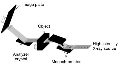
The angular intensity spectrum is measured in MIR in the following way. As shown in Fig. 1, a pair of perfect Si [3,3,3] crystals are used to monochromate and collimate an X-ray beam, which in the current implementation is a synchrotron but may be any suitable form of intense X-ray source. Once this beam passes through the subject, a third crystal (analyser crystal) of the same reflection index [3,3,3] diffracts the X-rays onto an image plate detector (Fuji HRV image plate, readout via a Fuji BAS2500 image-plate reader) or digital detector (50-µm resolution). The net effect of these three crystals is to allow precise analysis of the angular composition of the beam, because of the extreme angular selectivity of Bragg diffraction in perfect crystals. MIR data are obtained by collecting images at various angular positions of the analyser. In this way, a curve is measured at each pixel, which represents a smoothed measure of the angular intensity spectrum of the transmitted beam (i.e. the amount of energy travelling in various directions after passing through the object).
Fig. 1.
Schematic diagram of the imaging set-up at the National Synchrotron Light Source Laboratory.
Because of the object's spatially varying absorption coefficient and refractive index, the angular intensity spectrum of the X-ray beam is altered by its traversal through the object. Changes in the directionality of the beam are exceedingly small (on the order of microradians in angle), yet they are readily measured by the MIR method. After the angular intensity spectrum is obtained, it is analysed to determine how it has been perturbed by the object. This analysis procedure yields three images as follows.
MIR absorption image
X-ray absorption is determined in MIR at each pixel by measuring the proportion by which the area under the angular intensity spectrum of the beam has been diminished by the object. As with a conventional radiograph, the MIR absorption image shows variations in the absorption coefficient of tissue. The MIR absorption image can be interpreted in exactly the same way as a conventional radiograph; however, MIR images are much sharper and more accurate because they are virtually uncorrupted by radiation scattered by more than about 10 microradians. MIR absorption images are similar to DEI absorption images, but do not exhibit the artefacts and inaccuracies that are typically found in DEI images.
MIR refraction image
In MIR, the angle by which the beam has been refracted by the object is determined at each pixel by measuring the angular shift of the centroid of the beam. The MIR refraction image responds to variations in refractive index, which is approximately proportional to the mass density of the tissue. Specifically, the MIR refraction image highlights regions of abrupt spatial variations in mass density of the tissue, such as at the interfaces between tissues of different types. MIR refraction images are similar to DEI absorption images but, again, are far more accurate.
MIR USAXS image
Structures smaller than a pixel (< 50 µm) cannot be spatially resolved by MIR imaging; however, their presence causes minute beam deflections that can easily be detected by MIR. Specifically, microstructure in the object (on a scale from 1 to 50 µm) causes multiple refractions of the beam, which have the net effect of producing an angular spreading of the beam, known as USAXS. This spreading is assessed at every pixel by measuring the second central moment (variance) of the beam's angular intensity spectrum. Thus, a pixel in the USAXS image will be assigned a high value if the object is inhomogeneous within that pixel and if the inhomogeneities are larger than about 1 µm. Textural structure smaller than about 1 µm produces angular deflections that are larger than we can measure with MIR (> 20 microradians). These larger deflections are termed small-angle X-ray scattering (SAXS), which is a different phenomenon that is better described by diffraction theory.
Specimens
Four intact human cadaveric feet were procured from a surgical workshop through the courtesy of Ortheon Medical (Winter Park, FL, USA) and preserved in 10% formalin prior to imaging. In addition, four intact human cadaveric thumbs were procured from the gross anatomy laboratory. We have previously shown that the fixation procedure used has no effect on imaging (Mollenhauer et al. 2002).
Image acquisition
For the purposes of comparison, we used the synchrotron to acquire ‘conventional’ radiographs in addition to MIR images. In both cases, the same X-ray dose was used. These ‘conventional’ X-ray images, obtained by removing the analyser from the path of the beam, are similar to a clinical radiograph; however, they are better than clinical images because of the high quality of the synchrotron beam after it passes through the monochromator/collimator. In other words, these ‘conventional’ radiographs represent an upper performance bound for ordinary X-ray imaging.
The foot specimens were imaged in the lateral projection by ‘conventional’ radiography. The skin dose delivered was measured with an ion chamber and maintained by adjusting the speed of each scan. Thumb specimens were imaged as for foot specimens. Data were acquired using 40-keV X-rays at 11 analyser positions. The photon flux rate incident on the object was approximately 5.3 × 10⁶ ph s−1 mm−2. A skin dose of 0.12 mGy was delivered at each of the 11 analyser positions.
Results
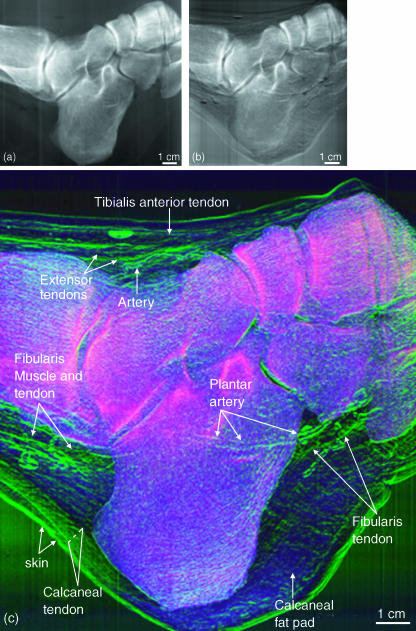
Subjective visual assessments of the image details were carried out by two of the investigators (C.M., J.L.). Figure 2 shows: (a) a representative ‘conventional’ X-ray image, (b) a raw image from the half-intensity point of the rocking curve and (c) a colour composite MIR image of a human foot. In Fig. 2(c), the attenuation (red), refraction (green) and USAXS (blue) images are shown fused together in a composite display. The raw image and MIR image clearly show soft tissue that cannot be seen in the conventional radiograph. The colour composite MIR image allows evaluation of tissue property signatures through colour coding. Thus, the skeletal elements, which are the densest material, display a red attenuation colour. Although the bones possess some scatter properties, it is the overwhelming attenuation of this tissue that predominates. The soft tissue elements can be easily discerned by their green colour, which demonstrates that their refractive properties are greater than their attenuation properties as compared with bone. The blue USAXS is seen overlying the regions that possess relatively more USAXS properties, such as the fatty tissue and other loose connective tissue, most notably that of the heel of the foot. It is expected that such tissues as tendons, ligaments, the edges of blood vessels and skin, and connective tissue frameworks would have refractive properties due to their line-forming structure with edges. But even the tendons can be discerned from their surrounding connective tissue due to slight differences in their X-ray refractive indices.
Fig. 2.
A ‘conventional’ radiograph (a), a raw image from the half intensity point of the rocking curve (b), and colour composite MIR image (c) of a human foot. Attenuation (red), refraction (green) and USAXS (blue) are shown together in a composite display.
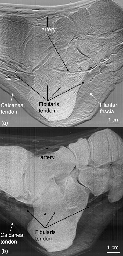
A comparison between the MIR refraction and USAXS images of the same specimen as in Fig. 2 can be seen in Fig. 3(a,b), respectively. In the refraction image, where the goal is not to quantify tissue properties but rather to delineate structures clearly, one can visualize the edges of the soft tissue structures as well as those of the bones. The X-ray refraction at tissue boundaries allows this delineation. By contrast, the USAXS image clearly shows the bones, which have high scatter properties due to the porosity of skeletal tissue, but also shows the loose connective tissues that possess scatter properties resulting from the loose arrangement of collagen and other fibres. In this image, it is noticeable that the very dense and tightly arranged fibres of the tendons are not picked up, but they are, nonetheless, easily identified because of the change in contrast between these tendons and their surrounding loose connective tissue. For instance, there is a sharp delineation between the calcaneal tendon and the surrounding loose connective tissue. Even the tendon of the fibularis muscle is visualized throughout because of its contrast against the scattering areolar tissue and bone. Thus, organized tissues, with a highly ordered arrangement such as that of the collagenous fibre bundles of a tendon, are not well imaged in USAXS, whereas the scattering properties of the non-linear fibres of loose connective tissue are clearly visible. This provides a distinction between tissue types.
Fig. 3.
Refraction (a) and USAXS (b) images of the same foot as in Fig. 2. Here, a comparison can be made between those structures with edge enhancement from X-ray refraction and those structures having tissues with scatter properties. For instance, in (a), the collagen fibre tissue of the calcaneal and fibularis tendons is readily visible owing to refraction at both fibre bundle edges and the whole tendon edges; these refractile properties differ somewhat from those of surrounding tissue, thus allowing visualization of these structures. Conversely, in (b), the organized parallel structure of the calcaneal and fibularis tendons lack significant scatter properties, and thus X-ray contrast. However, the surrounding fatty and less organized connective tissues display strong USAXS properties. Thus, the distinction between the two tissue types is evident.
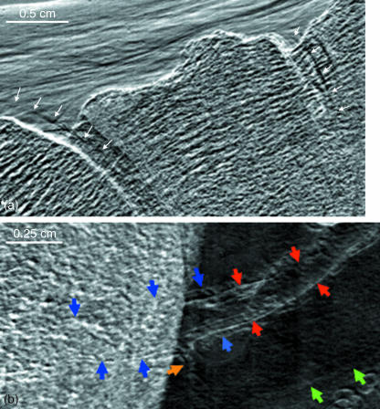
It was found that the articular cartilage of several of the joints was visible through MIR. Articular cartilage of the tibiotalar joint was consistently visible but the smaller joints were of variable iamge quality. Figure 4(a) is an enlargement of a portion of a refraction image of the cartilage of the talonavicular and naviculocuneiform joints (arrows), which was readily visible through MIR, most probably because these joints were positioned in a manner that would allow their imaging, unimpeded by superimposed skeletal elements. Although this cartilage has a density similar to that of the surrounding connective tissue, the edges of the cartilage can be delineated through X-ray refraction. Figure 4(b) is an enlargement of a region in which the plantar arteries course lateral to (and are therefore superimposed by) the calcaneus bone. The outline of one of the arteries can be delineated from the superimposed bone by virtue of the edge refraction. The artery can then be followed along its course in the plantar region. Additionally, the venae commitantes are identified on the sides of the artery. This was the only specimen of the four feet in which venae commitantes were visible.
Fig. 4.
(a) A refraction image of talo-navicular and naviculo-cuneiform joints in which the edges of the articular cartilage are visible in regions where they are, and are not, superimposed by bone. (b) Refraction image in which a plantar artery (red arrows) is flanked by venae commitantes (blue arrows). With some limitation, these structures can also be followed through their superimposition by the calcaneal bone. A smaller arterial branch is shown at the yellow arrow. The green arrows point to the inferior border of the tendon of the fibularis longus.
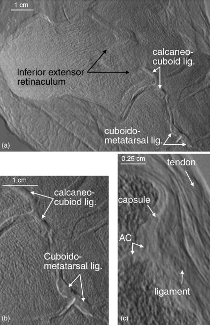
In one specimen, which was imaged in the lateral projection with approximately 20° lateral rotation from its sagittal plane, the larger and more prominent of the ligaments were visible. Figure 5(a) shows the inferior extensor retinaculum and calcaneocuboid and cudoidometatarsal ligaments. An enlargement of the latter two ligaments is shown in Fig. 5(b). Figure 5(c) is an enlargement of another joint in which the articular cartilage, joint capsule, ligament and passing tendon are identifiable. The more parallel arrangement of the collagen fibres within the tendon is apparent. Although the contrast does not differ among these tissues, knowing the anatomy of the region allows one to decipher between them due to the edge enhancement at each individual surface.
Fig. 5.
(a) A refraction image in which the inferior extensor retinaculum, calcaneo-cuboid and cuboidometatarsal ligaments are readily visible. (b) An enlargement of the calcaneo-cuboid and cuboidometatarsal ligaments. (c) An enlargement of a cuneonavicular joint showing the articular cartilage, joint capsule, ligament and tendon.
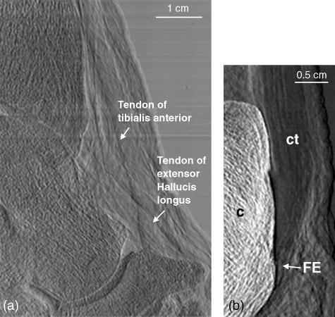
An enlargement of the dorsum of the ankle displaying the tendons of the tibialis anterior and extensor hallucis longus muscles is shown in Fig. 6(a). Figure 6(b) shows the attachment of the calcaneal tendon to the calcaneus bone. Close inspection allows the visualization of the parallel arrangement of the collagen fibre bundles comprising the tendon due to refraction at the fibre bundle surface. At the point of attachment of the tendon to the calcaneus, the fibrocartilaginous portion of the enthesis can be seen. It is clearly distinguishable from the surrounding collagen fibre bundles of the remainder of the tendon.
Fig. 6.
(a) A region of the ankle showing the tibialis anterior and extensor hallucis longus tendons dorsal to the tibiotalar and talonavicular joints. (b) The region of insertion of the calcaneal tendon to the calcaneus bone. The parallel arrangement of the fibres of the tendon is readily identified, particularly in contrast to the disorganization of the surrounding areolar connective tissue. The fibrocartilaginous enthesis (FE) can be readily delineated from the surrounding collagen fibre bundles of the rest of the tendon.
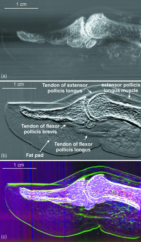
Figure 7 demonstrates the differences between a ‘conventional’ X-ray image (Fig. 7a) and two MIR images (Fig. 7b,c) of a human thumb. The ‘conventional’ X-ray image shows what would be expected from a clinical radiograph, i.e. only the calcified skeletal elements. However, the tendon, muscle and connective tissue elements of the thumb are readily distinguishable in Fig. 7(b). The composite colour image in Fig. 7(c) allows easy distinction between tissue properties, whereby those tissues that attenuate X-rays the most will appear red, those with high refraction gradients will appear green and those with the greatest USAXS contribution appear blue. Thus, although all tissues are imaged simultaneously, bony tissues can be discerned from soft tissues by colour assignment for these respective properties. Soft tissue, having the greatest disorganization, will exhibit the most USAXS.
Fig. 7.
(a) ‘Conventional’ radiograph of a human cadaveric thumb. (b) MIR refraction image of the same thumb, but now the tendons, muscle bellies and connective tissue arrangements are easily seen. Even the point at which the tendon of the flexor pollicis brevis splits to allow passage of the tendon of the flexor pollicis longus is demonstrated. (c) MIR colour image showing, as in the foot in Fig. 2, the attenuation in pink, refraction in green and scatter in blue.
Discussion
Conventional radiography allows the visualization of calcified tissues and, at low X-ray energies, shadows of soft tissues. Such low energies, however, increase the radiation dose to the patient. This present study demonstrates that a radiographic technique that goes beyond the attenuation of conventional radiography can allow visualization of soft tissue detail at higher X-ray energies, thus lowering the X-ray dose to the patient. MIR is capable of rendering X-ray images of high contrast showing soft tissue refraction and USAXS properties, while simultaneously detecting absorption in a human sample. Because of the contrast enhancement of this phase-sensitive imaging method, soft tissues are easily visualized with a clarity that no other radiographic technique has yet shown. Because the refraction and USAXS properties of a given tissue will vary with changes in morphology and architecture, such as in tumour development or interruption of connective tissue fibres, MIR has great potential for the identification of the presence or absence of pathological features, which will be the focus of our future work. Here we demonstrate that MIR is useful for discrimination among various tissue types: although they are imaged simultaneously, their tissue properties are distinguishable. Thus, hard tissues can be discriminated from muscle, tendon and less-organized soft tissues. Even the collagenous architecture which organizes the fat pad of the heel of the foot and fingertip is visible through MIR. Each of these structures is identifiable by its anatomical location and structure.
The utility of the refraction images is that, because of the refraction of X-rays at the tissue edges, the borders between structures are well delineated. We have previously shown that this is of particular value in the identification of surface irregularities, such as those of early cartilage degeneration as a result of osteoarthritis (Muehleman et al. 2003).
Those structures of less order, and thus of higher USAXS, are most distinguishable on the USAXS image. Thus, any disruption in the normal morphology of a particularly highly refractive rather than scattering tissue, such as a tendon, will lead to X-ray scatter at that point. This scatter signature of a tendon lesion should then be identifiable in its USAXS image. This is the case in tears or ruptures of the calcaneal tendon (our unpublished data). However, the goal of the present study was not to identify pathologies but rather to describe the appearance of normal tissues. The USAXS image allows for tissue type identification, whereby the less organized arrangement of the loose connective tissue is identified as such against the contrast differential of the more architecturally organized tendon tissues. These images together provide a more comprehensive description of the anatomical region. Furthermore, because MIR can produce multiple images of the same object, it offers the possibility of segmenting the images into various tissue types by classifying the multivariate signature of each pixel.
Because this study was carried out on post-mortem specimens, the question arises as to the effect of the slight movements and pulsations of perspective live individuals on the quality of the images. Small movements of the tissue will cause a motion blur of the images, in exactly the same way as in a conventional radiograph. Unlike holographic or other interferometric techniques, MIR is no more sensitive to motion than are other methods, because it does not depend on coherent phase effects.
Nevertheless, as in conventional radiography, motion may cause loss of resolution for very small structures in MIR. However, important small structures, such as articular cartilage withing small joints, are virtually invisible in conventional radiographs, whereas they are visible in MIR images.
To study the effect of motion, we are currently carrying out a study on the MIR of the degenerative changes in the articular cartilage of rabbit knee joints in vivo. This animal model requires resolution approximating to 10 µm (Muehleman et al. 2003), and thus the effect of any subtle movements will be apparent. The imaging times for MIR will be on the order of magnitude of ten times less than those for magnetic resonance imaging (MRI), a technique in which movements during imaging are not significant enough to invalidate results, and therefore we do not expect to see significant motion artefacts.
Although MIR requires several radiographic exposures, each can be proportionately shorter in duration, and thus MIR requires no more radiation dose than an individual X-ray exposure. Indeed, because MIR does not depend on absorption contrast (as with conventional radiography), it can be performed at high X-ray energy. Therefore, MIR can be performed with dose to the patient hundreds of times lower than with a conventional radiograph and our simulations show that it can be carried out in seconds.
Our current MIR implementation, which uses a synchrotron source of X-rays, is nearly ready for use in imaging of animals for longitudinal studies of disease and musculoskeletal pathologies, and for the evaluation therapeutic drugs. A clinical implementation using conventional X-ray tubes is currently in development, and preliminary indications are that the method will be feasible using powerful commercial X-ray tubes. The results presented here are encouraging evidence that clinical and research MIR devices will yield useful images of soft tissue. The new USAXS image provided by MIR provides a new kind of information that has not previously been seen in medical imaging, and the combined display of the absorption, refraction and USAXS images may lead to highly informative tissue classification capabilities based on the multivariate signatures of tissue across the three images.
Acknowledgments
This work was supported by NIH grants #RO1 AR48292 and CA111976.
References
- Aurich M, Kuettner KE, Muehleman C, Zhong Z, Chapman LD, Mollenhauer J. Die Darstellung von Gelenkknorpel des oberen Sprungegelenkes mit einem neuen Röntgenverfahren: ‘Diffraction-enhanced x-ray imaging (DEI)’ Fuβ- und Sprunggelenk. German J Foot Ankle Surg. 2003;1:2–7. [Google Scholar]
- Brankov JG, Wernick MN, Chapman LD, et al. Multiple-image computed tomography. Proceedings of the IEEE International Symposium on Biomedical Imaging. 2004;1:948–951. [Google Scholar]
- Chapman D, Pisano E, Thomlinson W, et al. Medical applications of diffraction enhanced imaging. Breast Dis. 1998;10:197–207. doi: 10.3233/bd-1998-103-419. [DOI] [PubMed] [Google Scholar]
- Li J, Zhong Z, Lidtke R, et al. Radiography of soft tissue of the foot and ankle with diffraction-enhanced imaging. J Anat. 2003;202:463–470. doi: 10.1046/j.1469-7580.2003.00175.x. [DOI] [PMC free article] [PubMed] [Google Scholar]
- Mollenhauer J, Aurich ME, Zhong Z, et al. Diffraction-enhanced X-ray imaging of articular cartilage. Osteoarthritis Cartilage. 2002;10:163–171. doi: 10.1053/joca.2001.0496. [DOI] [PubMed] [Google Scholar]
- Muehleman C, Chapman LD, Kuettner KE, et al. Radiography of rabbit articular cartilage with diffraction-enhanced imaging. Anat Rec A Discov Mol Cell Evol Biol. 2003;272:392–397. doi: 10.1002/ar.a.10043. [DOI] [PubMed] [Google Scholar]
- Muehleman C, Majumdar S, Issever AS, et al. X-ray detection of structural orientation in human articular cartilage. Osteoarthritis Cartilage. 2004;12:97–105. doi: 10.1016/j.joca.2003.10.001. [DOI] [PubMed] [Google Scholar]
- Wagner A, Aurich M, Sieber N, et al. Darstellung von Gelenkknorpel im Röntgenlicht: ‘Diffraction enhanced imaging (DEI)’. Orthop Praxis. 2003;39:171–177. [Google Scholar]
- Wernick MN, Wirjadi O, Chapman D, et al. Multiple-image radiography. Phys Med Biol. 2003;48:3875–3895. doi: 10.1088/0031-9155/48/23/006. [DOI] [PubMed] [Google Scholar]


