Abstract
The aim of this study was to visualize, at the ultrastructural level, the deformation and failure mechanism of cartilage matrix in the tensile mode. Full-thickness dumbbell-shaped specimens were prepared from adult bovines. There were two specimen groups; in the ‘parallel’ group the specimen axis was parallel to the split lines defining the preferential orientation of the collagen in the articular surface, and in the ‘perpendicular’ group the specimen axis was perpendicular to the split lines. Specimens were placed with the articular surface uppermost and subjected to a graded series of strain within individual mini-tension devices, while observed with stereomicroscopy and confocal laser scanning microscopy. Thereafter, the changes in the ultrastructure were observed with both scanning and transmission electron microscopy. The mechanism of cartilage failure in the tensile mode comprised the following stages, whether the strain was applied parallel or perpendicular to the split line. (1) At 0% strain a fibrillar meshwork within the articular surface was predominantly orientated in the direction of the split line. (2) As strain increased, the fibrillar meshwork became more orientated in the parallel group and reorientated in the perpendicular group in the direction of the applied strain. (3) After complete reorientation of the fibrillar meshwork in the direction of the applied strain, the initial sign of failure was rupture of the fibrillar meshwork within the articular surface. (4) Subsequently, the rupture rapidly propagated into the deeper layers. Greater strains were required for fibrillar reorientation and complete rupture in the ‘perpendicular group’ than in the parallel group.
Keywords: cartilage, collagen, confocal laser scanning microscopy, scanning electron microscopy, tensile strain, transmission electron microscopy, ultrastructure
Introduction
Articular cartilage is crucial to the normal function of the synovial joint, as its presence enables the articulating bones to move against each other with little frictional resistance and to transmit high loads while maintaining contact stresses at an acceptably low level (load bearing) (Meachim & Stockwell, 1979). The stiffness of cartilage and its load-bearing function are the result of the interaction between its constituents, these being the dense collagen fibrillar meshwork, the giant proteoglycan molecules trapped within the collagen meshwork and water. This well-known mechanism was first described by Maroudas (1976) and later by Hardingham & Fosang (1991). Accordingly, the hydrophilic proteoglycan molecules imbibe water and swell, thus expanding their volume many fold until they are prevented from further expansion by the constrains of the extremely tight collagen meshwork. Equilibrium is then achieved between the swelling pressure and the tension along the collagen fibrils (Mow & Ratcliffe, 1997).
The collagen meshwork is the structural component of cartilage and its three-dimentional (3-D) organization has been described according to two different (but not mutually exclusive) concepts: the split line concept (Hültkrantz, 1898) and the arcade concept (Benninghoff, 1925). The former proposed that the predominant orientation of the fibrillar meshwork within the articular surface is indicated by split lines induced in the articular surface by pricking with a sharp instrument, a suggestion which has been supported by scanning electron microscopy (SEM) (Walker et al. 1969) and transmission electron microscopy (TEM) studies (Bullough & Goodfellow, 1968; Meachim et al. 1974). The latter (arcade) concept proposed that the collagen fibrils anchored deeply in the calcified zone, run vertically towards the articular surface in the radial zone, turn obliquely in the transitional zone and become parallel to the articular surface in the tangential zone. This zone-related organization of the collagen–fibrillar meshwork has also been supported by SEM (Clarke, 1971, 1974; Speer & Dahners, 1979; Clark, 1990; Jeffery et al. 1991; Kääb et al. 1998) and TEM studies (Buckwalter et al. 1990).
As the collagen fibrillar meshwork is the primary restraint to the tensile strain within cartilage, it has been suggested that the failure of cartilage occurs as a result of breakdown of this collagen–fibrillar meshwork (Broom & Silyn-Roberts, 1990). A limited number of studies on cartilage tensile properties appear in the literature. The most notable are those by Kempson et al. (1973), Kempson (1979) and Woo et al. (1976). These studies showed that both the tensile modulus and the ultimate tensile strength of articular cartilage are higher in the direction parallel to the split line than perpendicular to it and also that they decreased with depth from the articular surface. Studies by Weightman et al. (1973, 1978) and Weightman (1976) focused on cartilage behaviour under cyclic tensile load and all demonstrated that cartilage exhibits typical fatigue behaviour. Although these excellent pioneering studies have shed much light on the directional and zonal variations in the tensile properties of cartilage and demonstrated the apparent consistency of these with the anatomical concepts (split line and arcade concepts) regarding the collagen organization described above, the ultrastructural details of deformation and failure in the tensile mode of this complex tissue (cartilage) are still far from understood.
The mechanism of cartilage deformation and failure in the tensile mode would be best understood if observed directly from the macroscopic level down to the ultrastructural level using various types of microscopic modalities, while specimens are still subjected to tensile strain. To this end, the aim of this study was to investigate such mechanisms by related microscopic observations using stereomicroscopy, phase-contrast microscopy, confocal laser scanning microscopy (CLSM), SEM and TEM. The specific objectives were as follows: (1) to visualize the overall structural changes of cartilage under graded series of strain using stereomicroscopy, phase-contrast microscopy and CLSM; (2) to visualize the ultrastructural changes of articular cartilage under tensile strain using SEM and TEM; (3) to investigate the failure mechanism of cartilage by integrating all the microscopic observations.
Materials and methods
Specimen preparation
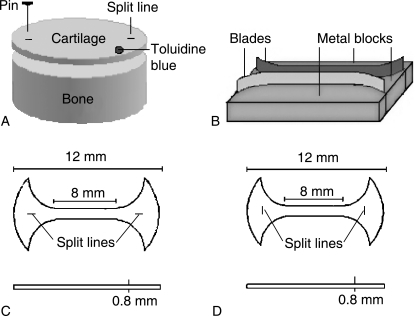
Five adult bovine knees, 2.5–3 years old, were obtained from a local abattoir within 2 h of slaughter. The femoral articular surfaces of these joints were examined to ascertain that they had no degenerative changes visible to the naked eye. Osteochondral plugs were harvested from the femoral trochlea using a cylindrical reamer with a 12-mm inside diameter. The femoral trochlea was chosen as the harvesting site for the following reasons. First, the split lines in the femoral trochlea have a more consistent orientation in the transverse (medio-lateral) direction than do those in the medial and lateral condyles, in which there is a tendency for the split-line pattern to vary even over a local region of the joint surface. Secondly, the flat surface of the femoral trochlea renders easy horizontal slicing of the articular surface, which is necessary to prepare the required tensile specimens. The articular surface of the periphery of each osteochondral plug was pricked multiple times with a metal pin dipped in India ink in order to reveal the split lines (Fig. 1A). Using a microtome, the full-thickness cartilage layer (approximately 800 µm thick) of each plug was sliced parallel to the articular surface. Using a specially made cutter (Fig. 1B), each cartilage disc was cut normal to the articular surface into a dumbbell-shaped specimen, 12 mm long and 1 mm wide. Two specimen groups were prepared. In one, which was designated the ‘parallel’ group; the specimen axis was parallel to the split lines, which in turn defined the preferential orientation of the collagen in the articular surface (Fig. 1C). In the other group, designated the ‘perpendicular’ group, the specimen axis was perpendicular to the split lines (Fig. 1D). Specimen numbers processed for various microscopic observations are given in Table 1.
Fig. 1. Preparation of tensile specimens.
A) The articular surface of each osteochondral plug was pricked with a metal pin dipped in India ink in order to reveal the split lines. Using a microtome, a full thickness of cartilage (approximately 800 µm thick) was sliced parallel to the articular surface. The articular surface is marked with toloidine blue (dot).
B) Using a custom-made dumbbell cutter, which consists of two metal blades and metal blocks, each cartilage disc was cut normal to the articular surface into a dumbbell-shaped specimen.
C) A schema of a dumbbell-shaped specimen with its long axis parallel to the split lines.
D) A schema of a dumbbell-shaped specimen with its long axis perpendicular to the split lines.
Table 1.
Specimen numbers processed for various microscopic observations
| Specimen numbers | ||||||||
|---|---|---|---|---|---|---|---|---|
| Specimen's groups | 0% strain | 5% strain | 10% strain | 15% strain | 20% strain | 25% strain | 30% strain | |
| CLSM | Parallel | 3 | 3 | 3 | 3 | 3 | 3 | 3 |
| Perpendicular | 3 | 3 | 3 | 3 | 3 | 3 | ||
| SEM | Parallel | 3 | 3 | 3 | 3 | 3 | 3 | 3 |
| Perpendicular | 3 | 3 | 3 | 3 | 3 | 3 | ||
| TEM | Parallel | 3 | 3 | 3 | 3 | 3 | 3 | 3 |
| Perpendicular | 3 | 3 | 3 | 3 | 3 | 3 | ||
Strain application to specimens
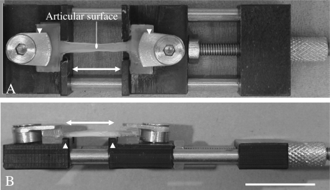
Both ends of each specimen were glued with cyanoacrylate between plastic plates. Each specimen was then mounted with the articular surface uppermost within an individual mini tension device, where it was subjected to a specific strain between 0% and that sufficient to cause failure (Fig. 2). The mini-tension devices were small enough to fit into the stages of all the microscopes used in this study (except for that of the TEM for which specific specimens were prepared as described later). The specimen extension was applied with a screw and nut mechanism and a complete turn of the screw corresponded to an extension of 0.5 mm. By noting the number of turns of the screw, it was possible to evaluate the extension and in turn the strain applied on a particular specimen. The strain was calculated as the extension divided by the original grip-to-grip distance.
Fig. 2. A mini tension device.
A) A view from the top shows that two compression screws and plates (arrow heads) clamp the both ends of a specimen. The specimen was subjected to a specific strain by turning the tension knob. A double headed arrow represents the direction of the applied strain.
B) A view from the side shows two parallel shoulders (arrow heads) in order to locate the specimen accurately. Bar, 10 mm.
Tissue processing for microscopic observations
Stereomicroscopy
While strain was applied to each specimen, photographic records were made at various strain values up to and including rupture propagation using a stereomicroscope (Zeiss, Germany) and digital camera (Nikon COOL PIX 950, Japan).
Phase-contrast microscopy
Changes in the organization of the matrix and cells within the articular surface resulting from strain application were also recorded using a phase-contrast microscope (Nikon ECLIPSE TS100, UK).
CLSM
Each specimen, having being subjected to a specific strain still within a mini-tension device, was fixed with 3.7% paraformaldehyde in 0.1 m PBS (pH 7.4) at ambient temperature by complete immersion, followed by washing with 0.1 m PBS for 30 min. Thereafter, each specimen was embedded in OCT compound (Tissue Tek®, Tokyo, Japan) to prepare five sections, 10 µm thick, using a cryo-microtome (Bright, Huntingdon, UK). Each section was permeabilized with 0.5% Triton X-100 (BDH, Poole, UK) in 0.1 m PBS for 20 min to allow the subsequent penetration of the fluorchrome conjugates, followed by washing with 0.1 m PBS. Each section was pre-incubated with 1% bovine serum albumin (BSA; Sigma, Poole, UK) in 0.1 m PBS for 30 min to block non-specific staining. After shielding from the light, filamentous actin was stained with 1 unit mL−1 of Alexa-Fluor 488®-conjugated phalloidin (Molecular Probes, Eugene, OR, USA) in 1% BSA in 0.1 m PBS for 30 min (in order to define the cell shape) and washed with 0.1 m PBS for 20 min. Each section was mounted on a glass slide and a cover slip was applied using Vector-shield anti-fade reagent (Vector Laboratories, Burlingame, CA, USA). The 488-nm argon-laser line was set at 5–10% of full power for excitation of the fluorchrome, while emission spectra were acquired between 500 and 535 nm. A z-series of optical sections through the full thickness of each specimen with a z-spacing of 0.5 µm was acquired at a slow scan speed (200 Hz) with four times linear averaging prior to image capture using a Leica SP2 AOBS (Leica, Germany). Phase-contrast (transmitted-light) and fluorescent images were simultaneously recorded to reconstruct 3-D projection images of the sections taken from the articular surface.
SEM
Changes in the ultrastructure were recorded in the SEM with specimens fixed at specific strains ranging from 0% strain to that at which failure occurred, while still gripped in their individual mini-tension device. Each specimen, still within its respective tension device, was fixed with 2.5% glutaraldehyde at ambient temperature for 2 h, treated with 700 units mL−1 of bovine testicular hyaluronidase (HSE; Worthington Biochemical Co., Lakewood, NJ, USA) for 6 h at 37 °C in order to expose the individual fibrils. Then each specimen was dehydrated through a graded series of ethanol from 50% to 100% for 3 h at ambient temperature. The specimens were soaked twice in 100% hexamethyldisilazane (HMDS, Polyscience Inc., USA) for 30 min each and then allowed to dry overnight. Thereafter, each specimen was sputter-coated and mounted on a brass stub holder in the SEM chamber [Jeol JSM-35 (Jeol Ltd, Japan) fitted with a ‘Genie’ digital control and imaging system (Deben Ltd, UK)], still within its individual tension device, and imaged at an accelerating voltage of 25 kV. All images were processed 16 times using a Kalman filter prior to image capture in order to remove noise.
TEM
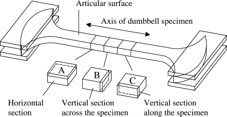
Some of the SEM specimens were further processed for TEM in order to observe the 3-D organization of the fibrillar meshwork. The specimens were fixed with 1% osmium tetroxide for 2 h, dehydrated through a graded series of ethanol from 50% to 100% for 30 min each and then infiltrated twice with 100% propylene oxide for 30 min each at ambient temperature. Thereafter, each specimen was infiltrated with EMIX™ epoxy resin (TAAB Laboratories Equipment Ltd, UK) for 2 days at ambient temperature. Before polymerization, the central portion of each specimen was cut into three blocks with a surgical scalpel in order to observe the 3-D organization of the constituent collagen fibrils (Fig. 3). Each tissue block was accurately orientated relative to the direction of the split lines and articular surface and set in a ‘coffin’ mould, which was then filled with resin for polymerization at 60 °C overnight. Ultrathin sections cut with a diamond knife (Diatome Ultra 45° Diamond knife, Leica Microsystems, UK) were picked up on grids (Agar Scientific Ltd, UK) and stained with 15% methanolic uranyl acetate for 10 min. Each ultrathin section was observed via a Phillips EM-400T at an accelerating voltage of 80 kV.
Fig. 3. Tissue blocks for preparing ultra-thin sections of TEM.
A) A cartilage block for preparing horizontal sections.
B) A cartilage block for preparing vertical sections across the axis of the specimen.
C) A cartilage block for preparing vertical sections along the axis of the specimen.
Results
Stereomicroscopy
Stereomicroscopy demonstrated that until 20% strain was reached, the specimens gradually narrowed as they were stretched. In both parallel and perpendicular groups, rupture initially occurred at the articular surface and subsequently spread throughout the depth of the cartilage. A measurably greater strain was required for complete failure of the perpendicular group (30.2 ± 5.4%, mean ± SD) compared with the parallel group (24.5 ± 4.8%).
Phase-contrast microscopy
The matrix substance appeared to become reorientated in the direction of the applied strain whether the strain was applied parallel or perpendicular to the split lines. After compete matrix reorganization, the rupture initially occurred within the articular surface in both parallel and perpendicular groups. The rupture then rapidly propagated into the subjacent layer. Again, greater strain was required for complete failure of the perpendicular group compared with the parallel group.
CLSM
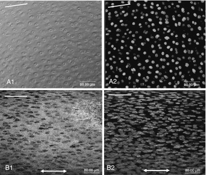
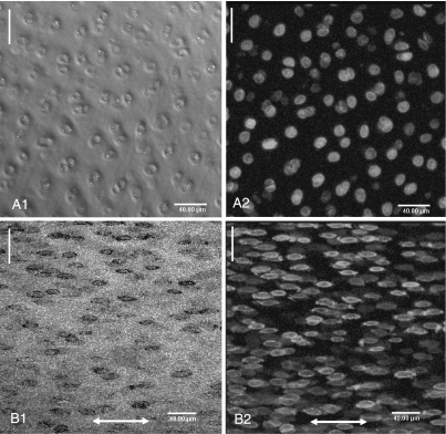
In both parallel and perpendicular groups, at 0% strain the preferential orientation of this matrix within the articular surface (as inferred from the arrangement of the cells in the phase-contrast and fluorescence images) was parallel to the split line (Figs 4A1,A2 and 5A1,A2). As strain increased, the matrix was reorganized in the direction of the applied strain in both groups (Figs 4B1,B2 and Fig. 5B1,B2). CLSM demonstrated that both matrix and cells within the articular surface were reorientated in the direction of applied strain, whether the strain was applied parallel or perpendicular to the split line. It confirmed also that greater strain was required for complete matrix reorganization in the perpendicular group than in the parallel group.
Fig. 4.
Confocal laser scanning micrographs (3-D projections) of the articular surface demonstrate the reorientation of the cartilage matrix under tensile strain in the parallel group. Phase contrast (A1, B1) and fluorescent (A2, B2) images. At 0% strain (A1, A2) the preferential orientation of the matrix within the articular surface, which surrounded pairs of cells, was parallel to the split line (white lines). At 15% strain (B1, B2) the matrix and cells were further reorganised in the direction of the applied strain (double headed arrow).
Fig. 5.
Confocal laser scanning micrographs (3-D projections) of the articular surface demonstrate the reorientation of the cartilage matrix in the perpendicular group. Phase contrast (A1, B1) and fluorescent (A2, B2) images. At 0% strain (A1, A2) the preferential orientation of the matrix within the articular surface, which surrounded pairs of cells, was parallel to the split line (white lines). At 20% strain (B1, B2) the matrix and cells were reorganized in the direction of the applied strain (double headed arrow).
SEM
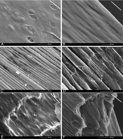
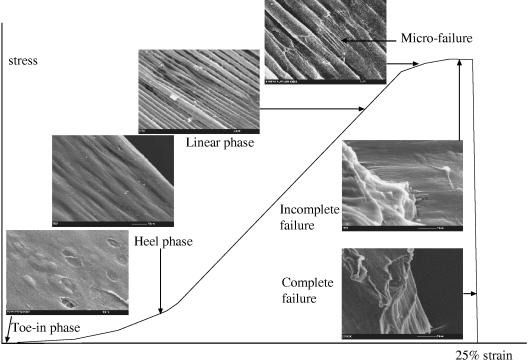
In the parallel group, at 0% strain the fibrillar meshwork within the articular surface was predominantly orientated in the direction of the split line and it overlaid the humps reflecting the underlying chondrocyte cavities (Fig. 6A). On application of strain, a ridge pattern formed on the articular surface and became more pronounced as the strain increased (Fig. 6B). Thus, at 15% strain, surface ridges that had the appearance of bundles of collagen fibrils (approximately 3 µm in diameter), which were aligned parallel to the direction of applied strain, became evident (Fig. 6C). At 20% strain, rupture of the sheath-like surface (or coating) of these ridges occurred, exposing a fibrillar structure inside the ridges (Fig. 6D). It was noteworthy that the initial sites of rupture of this sheath-like material occurred at sites with an apparent specific periodicity and at points closely aligned on groups of adjacent ridges. At 25% strain, complete rupture of the ridges in the articular surface exposed the fibrils in the subjacent layer, which realigned parallel to the applied strain (Fig. 6E). Finally, the rupture spread from the articular surface throughout the thickness of the articular cartilage as complete failure occurred (Fig. 6F).
Fig. 6. Scanning electron micrographs show the mechanism of cartilage failure in the tensile mode in the parallel group.
A) At 0% strain, the fibrillar meshwork within the articular surface was predominantly oriented in the direction of the split line (white lines) and overlaid the humps and underlaid the depressions reflecting the underlying chondrocyte cavities.
B) As strain increased, the ridges became evident on the articular surface. Double headed arrow represents the direction of applied strain.
C) At 15% strain, bundles of ridges (approximately 3 µm in diameter) which were aligned parallel to the direction of applied strain were more pronounced.
D) At 20 % strain, the rupture of the sheath-like material covering the ridges exposed the individual fibrils inside the ridges themselves. The rupture points appear to align in adjacent groups of ridges and have a regular periodicity.
E) At 25% strain, the articular surface ruptures. This rupture of the articular surface exposes the fibrils within the subjacent layer which aligned parallel to the applied strain.
F) Finally, the rupture spread from the articular surface throughout the thickness of the articular cartilage and results in the complete failure.
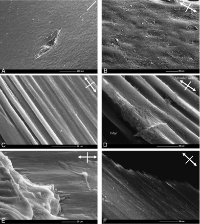
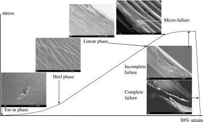
In both groups tested the response to the strain and mechanism of cartilage failure were similar and comprised two stages: (1) the matrix reorientation along the direction of the applied strain and (2) matrix failure, irrespective of whether the strain was applied parallel or perpendicular to the split line. However, much greater strain was required for complete fibrillar reorientation in the perpendicular group than in the parallel group (Fig. 7A–F).
Fig. 7. Scanning electron micrographs showing the mechanism of cartilage failure in the tensile mode in the perpendicular group.
Double headed arrow represents the direction of applied strain. Strain was applied perpendicular to the split line (white line).
A) At 0% strain, the fibrillar meshwork within the articular surface was predominantly oriented in the direction of the split line.
B) As strain increased, the ridges became evident on the articular surface. Double headed arrow represents the direction of applied strain.
C) At 15% strain, bundles of ridges (approximately 3 µm in diameter) which were aligned parallel to the direction of applied strain were evident.
D) At 25 % strain, there were initial signs of the rupture of the sheath-like material covering the ridges which exposed the individual fibrils inside the ridges themselves. Much greater strain was required for complete fibrillar reorientation in the perpendicular group compared to the parallel one.
E) At 30% strain, the articular surface ruptures. This rupture of the articular surface exposes the fibrils within the subjacent layer which aligned parallel to the applied strain.
F) Finally, the rupture spread from the articular surface throughout the thickness of the articular cartilage and results in the complete failure.
TEM
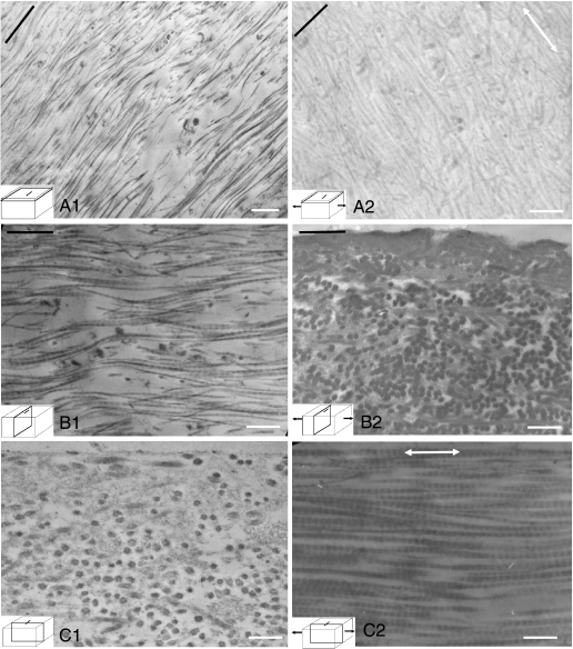
In the 3–5 µm below the articular surface (the region in which the ridges are seen to form by SEM), at 0% strain the majority of individual collagen fibrils were orientated predominantly parallel to the split lines (Fig. 8A1,B1,C1). However, some of the fibrils aligned at large angles to the split line direction. At 20% strain, however, as the ridges on the articular surface became evident in SEM, their constituent fibrils reorientated themselves to become aligned along the direction of the strain and the long axis of the ridges (Fig. 8A2,B2,C2). This occurred in the specimens both parallel and perpendicular to the split lines.
Fig. 8.
Transmission electron micrographs show the collagen orientation in the region immediately sub-adjacent to the articular surface of the specimens perpendicular to the split line at 0% and 20% strains. The black lines indicate the direction of the split lines. Double headed arrows indicate the direction of the applied strain. At 0% strain the predominant orientation of the fibrils was parallel to the split lines (A1, B1, C1), whereas at 20% strain the fibrils became aligned in the direction of applied strain (A2, B2, C2). Bar, 80 nm.
Discussion
Methodology and material
Cartilage is a complex material with anisotropic properties that are determined by the zonal differences in the content and orientation of collagen, its main structural constituent. Much knowledge on cartilage deformation and failure mechanism in the tensile mode has been gained from previous studies (Kempson et al. 1973; Woo et al. 1976; Broom, 1982, Broom, 1984, Broom & Marra, 1986, Broom & Silyn-Roberts, 1990; Broom et al. 2001). However, the ultrastructural events that occur when cartilage is subjected to increasing tensile strain up to that which causes failure have not been investigated systematically from the macroscopic level down to the ultrastructural level. The aim of this study was to understand this process by undertaking ultrastructural observations of cartilage specimens that have been subjected to tensile strain. It was determined from the outset that no single modality of microscopy would be adequate for this study. It was therefore decided to employ various appropriate modalities including traditional ones, i.e. stereomicroscopy, phase-contrast microscopy, SEM and TEM as well as the recently developed CLSM. Stereomicroscopy and phase-contrast microscopy demonstrated the macroscopic changes of the articular cartilage, whereas SEM and TEM were used to visualize the ultrastructural changes in the collagen meshwork. Thus, the mechanism of cartilage deformation and failure under tensile strain was observed from the macroscopic level down to the ultrastructural level. These related microscopic observations allowed the visualization of the process of ultrastructural changes from deformation of cartilage to its final rupture in a much clearer manner than in previous studies. Moreover, the use of full-thickness cartilage specimens was justified as it allowed visualization of the process of deformation and propagation of failure throughout the various layers of cartilage. The nature of the investigation precludes any serious attempt to observe changes in the ultrastructure of cartilage in real time while it is being subjected to tensile strain. We therefore opted to observe these changes in different cartilage specimens (matched in the orientation of collagen as closely as possible), each of which was subject to a specific strain in an individual mini-tension device. Each specimen was kept in the strained condition within its specific device and fixed as appropriate for SEM and TEM investigations.
Although human cartilage specimens would have been preferable, it was not possible to obtain a sufficient supply of fresh and normal specimens of uniform quality. Fresh adult bovine cartilage from the femoral trochlea region of the knee joint was used instead. This was possible to obtain in abundance and ensured uniformity of quality and properties in the large number of specimens required for this study. The particular site in the knee (femoral trochlea) chosen for harvesting the specimens allowed essentially flat specimens to be obtained.
Findings of this study
The various microscopic observations have been corroborative in describing cartilage response to increasing tensile strain. Two distinct stages have been identified, namely matrix reorganization followed by matrix failure, irrespective of whether the strain was applied parallel or perpendicular to the split line. Both of these had some salient features.
Matrix reorganization
A remarkable observation was that, whether the strain was applied in the parallel or perpendicular direction to the split line which defined the preferred orientation of the collagen in the articular surface, the collagen meshwork became aligned parallel to the direction of the applied strain. The CLSM images showed the chondrocytes to deform and become elongated with their axis parallel to the applied strain in both groups. The SEM images demonstrated the same phenomenon but with greater detail. When a specimen was stretched in the direction of preferred orientation of collagen (parallel group), the ridges formed on the articular surface were occasionally greater in number and had a sharper appearance than those formed when a specimen was stretched in the perpendicular direction to the split lines (perpendicular group). Thus, in the former the collagen fibrils became orientated more in the preferred direction, whereas in the latter they were subject to total re-orientation. This complete reorganization of the collagen meshwork occurred at a higher strain in the latter specimens than in the former. The TEM images illustrated, in addition to this, the re-orientation of the individual collagen fibrils in the direction of applied strain, whether the strain was applied parallel or perpendicular to the split lines. The above observation is consistent with the study by Kamalanathan & Broom (1993). Their TEM study demonstrated that local groupings of fibrils can be found within the vicinity of the split lines that are clearly aligned to it. However, it was equally possible to find similar fibrillar groupings aligned at large angles to the split line direction. Their ultrastructural observations led to their conclusion that the split line did not correlate strongly with a preferred direction for the collagen fibrils in the articular surface. Indeed, they found that the most distinctive feature of the articular surface is its high degree of structural variability. The ridge formations observed in our study could therefore have been an indication of tensing of those fibrils, which were most closely parallel to the direction of the applied strain. Ridges increased in number as other fibrils aligned themselves in response to increased strain.
Matrix failure
The SEM images demonstrated that the initial sign of cartilage failure was the rupture of a sheath-like fibrillar meshwork within the articular surface, revealing the bundles of fibrils inside these ridges formed on strain application. Subsequently, the articular surface itself ruptured, but not the subjacent layers (i.e. there was incomplete failure). The fibrillar meshwork of the subjacent layer was next aligned in the direction of the applied strain. Finally, complete failure was observed as the subjacent layers rapidly ruptured in turn. The perpendicular group of specimens required the application of a measurably greater strain (30% vs. 25%) for complete matrix (collagen) reorientation than did the parallel group. These small differences in the strains required for complete matrix reorientation between the two groups are again consistent with results of Kamalanathan & Broom (1993) in that they confirmed less pronounced organization of collagen in the articular surface of bovine cartilage.
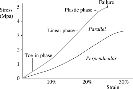
Furthermore, for either group of specimens, it can be summarized that each individual morphological feature seen on the scanning electron micrographs corresponds to a phase of the stress–strain curve. Thus, in the toe-in phase, cartilage withstands the stress by modifying its structure, i.e. the first phase of its collagen reorganization. In the linear phase, the stiffness of cartilage increases as its collagen organization becomes less random. In the plastic phase, cartilage is so stressed that its structure, i.e. collagen organization, almost fails (Fig. 9). In the stress–strain curve, the perpendicular group of specimens were characterized by prolonged toe-in and heel phases, which correspond to a greater degree of matrix reorganization. The scanning electron micrographs representing the failure mechanism of cartilage matrix in the tensile mode for both the parallel and the perpendicular groups are summarized on the schematic stress–strain graphs (Figs 10 and 11). They demonstrate quite similar behaviour except that the latter failed at a measurably (but not considerably) higher strain.
Fig. 9.
Stress strain curves of the cartilage specimens which orientate either parallel or perpendicular to the split line. The tensile modulus is greater in the specimen parallel to the split line than in the specimen perpendicular to the split line. The specimen (800µm in thick) was taken from the articular surface of adult bovine cartilage of the femoral trochlea. The strain rate was 1% per second.
Fig. 10.
Relationship between the structure of articular cartilage and the applied strain in specimens parallel to the split line.
Fig. 11.
Relationship between the structure of articular cartilage and the applied strain in specimens perpendicular to the split line.
Anisotropy of cartilage tensile properties and collagen organisation
The findings of this study confirmed the observation by Kamalanathan & Broom (1993) regarding the orientation of collagen in the superficial layer relative to the split lines, which they have demonstrated to be less strong than previously thought. This observation was also confirmed in a study by Verteramo & Seedhom (2004), which investigated the tensile properties of adult bovine cartilage. Whereas specimens orientated parallel to the predominant orientation of collagen were found to be stiffer than those tested in the perpendicular direction, the anisotropy is much less pronounced than that previously reported for human cartilage (Kempson et al. 1973; Kempson, 1979). If the anisotropy is expressed as the ratio of the tensile strength of a specimen tested in the parallel direction to that tested in the perpendicular direction, this ratio in the study by Verteramo & Seedhom (2004) was 1.6–2 whereas in the studies by Kempson it was 3, indicating a greater degree of anisotropy in the human cartilage than in the bovine. There may be interspecies differences in the organization of collagen that have yet to be investigated.
Conclusions
Related microscopic observations using light, confocal and electron microscopy were introduced for demonstrating the mechanism of cartilage deformation and failure in the tensile mode. Whether the strain was applied parallel or perpendicular to the split lines, the collagen meshwork within the articular surface was reorganized in the direction of the applied strain. This collagen reorganization plays an important role in the mechanism of cartilage deformation (extension) under tensile loads. After the fibrillar meshwork within the articular surface was completely aligned in the direction of the applied strain, cartilage failure was initiated by the rupture of the articular surface. Finally, complete failure was observed as the subjacent layers rapidly ruptured. Greater strains were required for complete fibrillar reorientation and rupture in the perpendicular group than in the parallel group.
Acknowledgments
We gratefully acknowledge Professor Toyama, Assistant Professor Matsumoto and Dr Otani, Department of Orthopaedic Surgery, Keio University, for their support. We also gratefully acknowledge the contribution of Mr Whitham and Mr Pullan for the design and manufacture of the tension machine and Mrs Hudson for her technical instructions with regard to tissue preparation.
References
- Benninghoff A. Form und Bau der Gelenkknorpel In Ihren Bezieheugen zur Funktion. Z Zellforschung Mikroskopishe Anat Zur Funktion. 1925;II:783–837. [Google Scholar]
- Broom ND. Abnormal softening in articular cartilage: its relationship to the collagen framework. Arthritis Rheum. 1982;27:1028–1039. doi: 10.1002/art.1780251010. [DOI] [PubMed] [Google Scholar]
- Broom ND. Further insights into the structural principles governing the function of articular cartilage. J Anat. 1984;139:275–294. [PMC free article] [PubMed] [Google Scholar]
- Broom ND, Marra DL. Ultrastructural evidence for fibril-to-fibril associations in articular cartilage and their functional implication. J Anat. 1986;146:185–200. [PMC free article] [PubMed] [Google Scholar]
- Broom ND, Silyn-Roberts H. Collagen–collagen versus collagen–proteoglycan interactions in the determination of cartilage strength. Arthritis Rheum. 1990;33:1512–1517. doi: 10.1002/art.1780331008. [DOI] [PubMed] [Google Scholar]
- Broom ND, Chen MH, Hardy A. A degeneration-based hypothesis for interpreting fibrillar changes in the osteoarthritic cartilage matrix. J Anat. 2001;199:683–698. doi: 10.1046/j.1469-7580.2001.19960683.x. [DOI] [PMC free article] [PubMed] [Google Scholar]
- Buckwalter JA, Rosenberg LC, Hunziker EB. Articular cartilage: composition, structure, response to injury, and methods of facilitating repair. In: Ewing JW, editor. Articular Cartilage and Knee Joint Function. New York: Raven Press; 1990. pp. 19–56. [Google Scholar]
- Bullough PG, Goodfellow J. The significance of the fine structure of articular cartilage. J Bone Joint Surg. 1968;50-B:852–862. [PubMed] [Google Scholar]
- Clark JM. The organization of collagen fibrils in the superficial zones of articular cartilage. J Anat. 1990;171:117–130. [PMC free article] [PubMed] [Google Scholar]
- Clarke IC. Articular cartilage: a review and scanning electron microscope study. 1. The interterritorial fibrillar architecture. J Bone Joint Surg. 1971;53-B:732–750. [PubMed] [Google Scholar]
- Clarke IC. Articular cartilage: a review and scanning electron microscope study II. The territorial fibrillar architecture. J Anat. 1974;118:261–280. [PMC free article] [PubMed] [Google Scholar]
- Hardingham T, Fosang AJ. Aggrecan, the chondroitin sulphate / keratan sulphate proteoglycan from cartilage. In: Kuettner KE, Schleyerbach R, Peyron JG, Hascall VC, editors. Articular Cartilage and Osteoarthritis. New York: Raven Press; 1991. pp. 5–20. [Google Scholar]
- Hültkrantz W. Über die Spaltrichtungen der Gelenkknorpel. Verhandlungen Anat Gesellschaft. 1898;12:248–256. [Google Scholar]
- Jeffery AK, Blunn GW, Archer CW, Bently G. Three-dimentional collagen architecture in bovine articular cartilage. J Bone and Joint Surg. 1991;73-B:795–801. doi: 10.1302/0301-620X.73B5.1894669. [DOI] [PubMed] [Google Scholar]
- Kääb MJ, Gwynn IAP, Nötzli HP. Collagen fibre arrangement in tibial plateau articular cartilage of man and other mammalian species. J Anat. 1998;193:23–34. doi: 10.1046/j.1469-7580.1998.19310023.x. [DOI] [PMC free article] [PubMed] [Google Scholar]
- Kamalanathan S, Broom ND. The biomechanical ambiguity of the articular surface. J Anat. 1993;183:567–577. [PMC free article] [PubMed] [Google Scholar]
- Kempson GE, Muir H, Polard C, Tuke M. The tensile properties of the cartilage of human femoral condyles related to the content of collagen and glycoseaminoglycans. Biochim Biophys Acta. 1973;297:456–472. doi: 10.1016/0304-4165(73)90093-7. [DOI] [PubMed] [Google Scholar]
- Kempson GE. Mechanical properties of articular cartilage. In: Freeman MAR, editor. Adult Articular Cartilage. London: Pitman Medical; 1979. pp. 333–414. [Google Scholar]
- Maroudas AI. Balance between swelling pressure and collagen tension in normal and degenerate cartilage. Nature. 1976;260:808–809. doi: 10.1038/260808a0. [DOI] [PubMed] [Google Scholar]
- Meachim G, Denham D, Emery IH, Wilkinson PH. Collagen alignments and artificial splits at the surface of human articular cartilage. J Anat. 1974;118:101–118. [PMC free article] [PubMed] [Google Scholar]
- Meachim G, Stockwell RA. The matrix. In: Freeman MAR, editor. Adult Articular Cartilage. London: Pitman Medical; 1979. pp. 1–68. [Google Scholar]
- Mow VC, Ratcliffe A. Structure and function of articular cartilage and meniscus. In: Mow VC, Hayes WC, editors. Basic Orthopaedic Biomechanics. Philadelphia: Lippincott-Raven Publishers; 1997. pp. 113–177. [Google Scholar]
- Speer DP, Dahners L. The collagenous architecture of articular cartilage. Correlation of scanning electron microscopy and polarized light microscopy observations. Clin Orthop. 1979;139:267–275. [PubMed] [Google Scholar]
- Verteramo A, Seedhom BB. Zonal and directional variations in tensile properties of bovine articular cartilage with special reference to strain rate variation. Biorheology. 2004;41:203–213. [PubMed] [Google Scholar]
- Walker PS, Sikorski J, Longfield MD, Wright V, Buckley T. Behaviour of synovial fluid on surface of the articular cartilage. Ann Rheum Dis. 1969;28:1–14. doi: 10.1136/ard.28.1.1. [DOI] [PMC free article] [PubMed] [Google Scholar]
- Weightman BO, Freeman MA, Swanson SA. Fatigue of articular cartilage. Nature. 1973;244:303–304. doi: 10.1038/244303a0. [DOI] [PubMed] [Google Scholar]
- Weightman BO. Tensile fatigue of human articular cartilage. J Biomech. 1976;9:193–200. doi: 10.1016/0021-9290(76)90004-x. [DOI] [PubMed] [Google Scholar]
- Weightman BO, Chappell DJ, Jenkins EA. A second study of tensile fatigue properties of human articular cartilage. Ann Rheum Dis. 1978;37:58–63. doi: 10.1136/ard.37.1.58. [DOI] [PMC free article] [PubMed] [Google Scholar]
- Woo SLY, Akeson WH, Jemmott GF. Measurements of nonhomogeneous, directional mechanical properties of articular cartilage in tension. J Biomech. 1976;9:785–791. doi: 10.1016/0021-9290(76)90186-x. [DOI] [PubMed] [Google Scholar]


