Abstract
Microcracks have been implicated in the loss of bone quality for osteoporosis. In order to detect and monitor their growth, and to use these data to predict fractures, it is essential to obtain quantitative data regarding their shape in three dimensions. Beam-shaped bone samples from sheep radii were prepared and stained with fluorochrome dyes and tested in cyclical fatigue under four-point bending in a servo-hydraulic fatigue-testing machine. Samples were tested at a frequency of 30 Hz under load control at a stress range of 100 MPa. Holes were drilled into bone samples and used as reference points for reconstructions. A series of thin longitudinal sections were cut using a sledge macrotome. A two-dimensional image of each section was examined using an epifluorescence microscope and images transferred to a PC via a CCD low-light colour video camera. A three-dimensional image of each microcrack was reconstructed using computer software, and its dimensions measured. Cracks were elliptical in shape, longer in the longitudinal direction and with a mean aspect ratio of 5.5 ± 1.05. The mean (± SD) length and width of labelled microcracks were 488 ± 151 and 88 ± 21 µm, respectively.
Keywords: bone quality, computer reconstruction, epifluorescence microscopy, fatigue damage, longitudinal sections
Introduction
Osteoporosis is a disease characterized by loss of bone mass and changes in tissue microarchitecture of the bone, which compromise bone quality. Bones become fragile and prone to fracture. There is a growing awareness that a reduction in bone mineral density is not the sole pathology underlying osteoporosis; the missing factor appears to be bone quality. Although a precise definition of bone quality is difficult to obtain, it includes parameters such as morphology of bone, rate of bone turnover, the degree of mineralization of bone matrix and the amount of microdamage present in the bone tissue (Bouxsein, 2003).
Fatigue damage in bone manifests itself in the form of microcracks. Such cracks have been implicated in physiological phenomena, including stress fractures (Burr et al. 1990), remodelling (Burr et al. 1985; Martin, 1992; Mori & Burr, 1993; Bentolila et al. 1998; Verborgt et al. 2000) and adaptation (Prendergast & Taylor, 1994; Lee et al. 2002). The origin of damage at the ultrastructural level is not known. It is hypothesized that damage at the ultrastructural level is caused by the cracking of bone mineral crystallites, debonding at the mineral organic interface or shear between and within the collagen fibrils.
Microdamage accumulation has an effect on bone toughness or resistance to fracture (Currey et al. 1996; Vashishth et al. 1997; Mashiba et al. 2000; Vashishth, 2000; Zioupos, 2001; Nalla et al. 2004). Toughness depends on the critical stress intensity factor, which, in turn, is a measure of crack initiation; a measure of damage accumulation preceding a macrocrack; and the energy required for crack propagation. Microdamage tends to accumulate with age and this may have an effect on bone tissue properties and ultimate fracture risk (Schaffler et al. 1995). Knowledge of true crack dimensions and variance in size are required for calculation of stress intensity values, which indicate the probability of an individual microcrack propagating to cause a stress or fragility fracture (Taylor, 1998).
Cracks are normally measured using two-dimensional transverse sections of bone, in which they appear as straight or curved lines, 50–100 µm in length, in samples ex vivo (Frost, 1960; Schaffler et al. 1989; Burr & Stafford, 1990; Lee et al. 1998, 2000). Occasionally they are measured on longitudinal sections, where they appear much longer (Burr & Martin, 1993). But such conventional methods of measuring cracks on random transverse or longitudinal sections convey limited information, especially regarding the three-dimensional (3D) shape and size of microcracks. Taylor & Lee (1998) used sterology to estimate 3D sizes and shapes using data from 2D sections in the transverse and longitudinal planes. Their analysis predicted an elliptical crack 66–113 µm in width and 4–5 times longer in length (264–565 µm).
O'Brien et al. (2000) studied in vivo microcracks in human rib sections bulk-stained in basic fuchsin and viewed in the longitudinal plane and in three dimensions using laser scanning confocal microscopy (LSCM) of thick transverse sections as well as serially sectioning methylmethacrylate-embedded bone specimens. Using both techniques they found that cracks were approximately elliptical in shape, with a mean length of 404 ± 145 µm (mean ± SD) in the longitudinal direction and a mean width of 97 ± 38 µm in transverse section. However, using LSCM, it was not possible to determine how much of the crack had been cut away during the sectioning process and so no quantitative data were obtained on 3D crack measurements using confocal reconstruction.
The serial sectioning technique used by O'Brien et al. (2000) used a limited reference system to reconstruct microcracks. Basic fuchsin was used to stain microcracks, but, because this dye is dissolved in ethanol, it has been argued that cracks may develop using this staining regime (Boyde, 2003).
Methylmethacrylate is the most commonly used embedding medium for sectioning undecalcified bone. However, a number of problems are associated with its use as it has a long infiltration time, requires strict temperature control and reacts with many polymers, and hence only glassware can be used for embedding.
This study aims to obtain more data on the 3D behaviour of microcracks and to develop the technique used by O'Brien et al. (2000) by obtaining high section quality using Kleer set resin™ as an embedding medium rather than methylmethacrylate, by using fluorochrome dyes rather than basic fuchsin and by employing fixed reference points.
Materials and methods
Fluorochrome-labelled sheep radii from seven skeletally mature female Suffolk crossbred sheep from a previous study were selected (Lee et al. 2002; Lee & Taylor, 2003). Specimens were cut from the medial aspect of the radial diaphysis using a band saw. Beam-shaped specimens were prepared using a diamond saw and milling machine. Each specimen was 40 mm long and had a width and a height (Fig. 1) corresponding to the minimal thickness of the cortex (mean width × height was 7 × 2.6 mm). The specimens were wrapped in clingfilm and stored at −20 °C prior to testing. On the day of testing, specimens were thawed in de-ionized water for 1 h, and stained with 0.0005 m alizarin in a desiccator under vacuum (6.66 kPa) for 16 h to label pre-existing damage (O'Brien et al. 2002). The specimens were then placed in a bath of 0.0005 m calcein or xylenol orange and tested in cyclical fatigue under four-point bending in an INSTRON 1341 servo-hydraulic testing machine at a frequency of 30 Hz until failure occurred. The samples were tested using load control with a stress range of 11–110 MPa. Tests were carried out at room temperature and specimens were kept wet during all stages of machining and testing.
Fig. 1.
Beam-shaped specimen. Mean width (w) and height (h) was 7 × 2.6 mm and each specimen was 40 mm long.
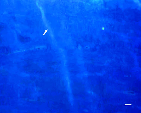
Holes were drilled into two ends of the bone specimens. The specimens were dehydrated through a graded series of alcohol (80, 90, 95 and 100% each for 1 day). A new styrene-based polyster casting resin, ‘Kleer set resin™’ (Metprep Ltd) was used for embedding at room temperature. In order to test the visibility of fluorochrome through the new embedding medium used, one end of the beam specimen was sectioned transversely using a ground section technique (Frost, 1958). The embedded block was mounted on a wooden block using cyanoacrylate glue. Longitudinal sections 15–25 µm in thickness, through a depth of about 200–300 µm, were obtained using a sledge macrotome (LKB 2260). The cutting speed was set at 1–2 mm s−1, which gave good control, and the clearance angle was set at 9–10°. Sections were initially collected on a macrotome blade in sequence and a drop of 90% ethanol was poured on each section to soften and flatten folds or creases. They were removed from the blade and placed directly on to a glass slide using a soft paintbrush. The sections were air dried and, before the edges had begun to curl, were transferred to a new, dry slide. The slides were mounted using DPX and a cover slip. Microcracks were identified using the criteria described by Lee et al. (1998) for epifluorescence microscopy. Once a well-stained microcrack was identified in a slide and it was determined that it was not artefactual (Fig. 2), then the same microcrack was identified in all consecutive slides in series. This technique was repeated through the entire depth of the microcrack. Microcrack images were then transferred to a PC using a CCD colour video camera. Multiple images were captured in the vicinity of the crack for each serial section in order to develop a montage (using Adobe Photoshop 6.0), which included the drill hole acting as a reference point. The serial slices were reconstructed into 3D images of each individual microcrack using Surfdriver™ computer software (John A. Burns School of Medicine, University of Hawaii, Honolulu). The software allowed the reconstructed image to be rotated. Measurements of crack lengths in both transverse and longitudinal directions were made from the reconstructed images.
Fig. 2.
Longitudinal section of fluorochrome-labelled bone viewed with UV epifluorescence (λ = 365 nm). An artefactual microcrack is arrowed. Scale bar = 200 µm.
Results
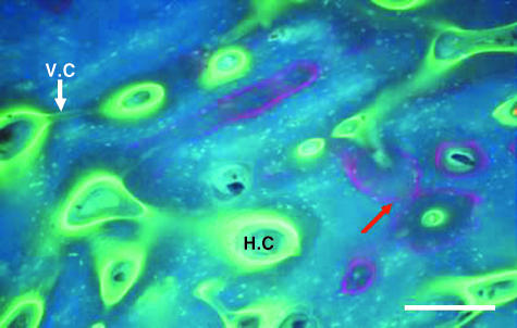
High-quality sections of bone were obtained using the new embedding medium. During sectioning, little cracking and folding was observed and the sections proved easy to mount. Figure 3 shows an example of a transverse section of bone viewed using UV epifluorescence. The fluorescent agents alizarin, administered in vivo (Lee & Taylor, 2003), and calcein, administered in vitro, are distinct. Calcein has penetrated the tissue (Fig. 3a) and has labelled porosities within the bone such as Haversian canals, resorption cavities, lacunae and canaliculi.
Fig. 3.
Transverse section of fluorochrome-labelled bone viewed with UV epifluorescence (λ = 365 nm) to test the visibility of fluorochromes in the new embedding medium. Calcein was used to stain fatigued bone specimens and has penetrated the bone tissue and labelled canaliculi, lacunae, Haversian canal (H.C) and Volkmann's canals (V.C) connecting two Haversian canals. Alizarin (red arrow) was administered in vivo in an earlier study (Lee & Taylor, 2003). Scale bar = 250 µm.
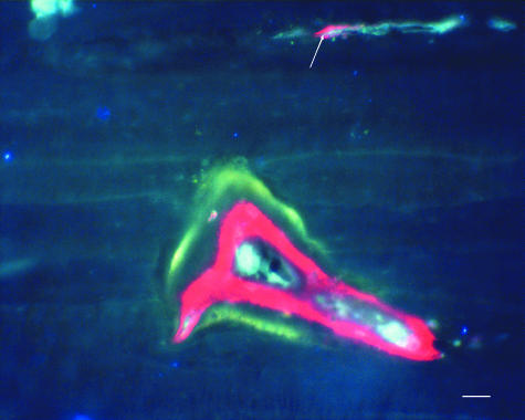
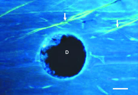
Alizarin has labelled the pre-existing micrcracks as shown in Fig. 4. Calcein clearly labelled microcracks generated during fatigue testing in all samples. Calcein fluoresces green under UV (λ = 365 nm) and orange under green epifluorescence (λ = 546 nm). Microcracks appeared as thin, wavy lines and several were oblique to the osteonal axis (Fig. 5). The edges of the drill hole were intact, demonstrating high-quality sectioning.
Fig. 4.
Beam-shaped bone specimens were stained with alizarin to label pre-existing microcracks. Alizarin fluoresces red under UV light (λ = 365 nm) and has labelled the pre-existing microcrack (arrow) on the edge of a sectioned Haversian canal. An osteon labelled with alizarin (inner red label) and calcein (outer green label) is also visible. Scale bar = 50 µm.
Fig. 5.
Example of calcein-stained oblique microcracks shown (arrows) in a longitudinal section of bone. The drill hole (D), which is used as a reference point for aligning sections, is shown. Slide is viewed under UV light (λ = 365 nm). Scale bar = 100 µm.
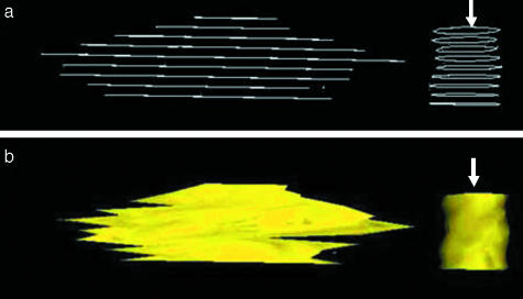
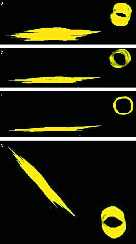
Some microcracks were found to propagate parallel to the longitudinal axis of the bone. A microcrack was traced through consecutive sections, and reconstructions of this microcrack are shown in Figs 6 and 7. The software can create an outline or skeletal image of the microcrack in all the sections (Fig. 6a) and the overall shape of a microcrack, including all the sections, by placing a ‘skin’ over them (Fig. 6b). The reconstructed image of this microcrack is rotated (Fig. 7a–d) in order to view its shape from different angles. The reconstructed image of the drill hole appears as a tube and aids in interpreting microcrack orientation.
Fig. 6.
Initial reconstruction of a microcrack and hole (arrow) drilled into the bone specimen. (a) An example of a ‘skeletal’ reconstruction demonstrating alignment of individual sections. (b) Image of the same microcrack and drill hole shown with a ‘skin’ covering placed around it using Surfdiver™.
Fig. 7.
(a–d) Stepwise reconstruction of a microcrack rotated at various angles (yellow). The drill hole is also reconstructed as a cylinder (h) and allows understanding of the orientation of the microcrack as it is rotated at various angles.
Table 1 summarizes the data obtained from the crack reconstructions obtained from the serial sectioning technique. Ten microcracks were reconstructed from seven different adult sheep. The reconstructed microcracks had an elliptical shape (Fig. 7d). Mean crack length in longitudinal directions was found to be 488 ± 151 µm, and measured crack width was 88 ± 21 µm. The mean aspect ratio of longitudinal to transverse length was 5.5 ± 1.05.
Table 1.
Mean microcrack data obtained from reconstructed serial sections; microcrack lengths in both longitudinal and transverse planes and mean aspect ratio of longitudinal to transverse length are shown
| No. of traced microcracks | Crack length (µm) | Crack width (µm) | Length/width ratio |
|---|---|---|---|
| 1 | 392 | 94 | 4.2 |
| 2 | 480 | 92 | 5.2 |
| 3 | 570 | 110 | 5.2 |
| 4 | 534 | 100 | 5.3 |
| 5 | 444 | 89 | 5.0 |
| 6 | 671 | 87 | 7.7 |
| 7 | 363 | 55 | 6.6 |
| 8 | 771 | 120 | 6.4 |
| 9 | 281 | 55 | 5.1 |
| 10 | 373 | 80 | 4.6 |
| Mean | 488 | 88 | 5.5 |
| SD | 151 | 21 | 1.05 |
Discussion
This study has expanded upon the technique used by O'Brien et al. (2000) to view the shape of microcracks in three dimensions by modifying the staining technique, embedding medium and by using fixed reference points. Kleer set resin™ (Metprep Ltd) was used as an embedding medium and provided good quality serial sections. It was found to be much simpler and quicker to use than methylmethacrylate (Mohsin et al. 2002). Fluorochrome-labelled agents within the bone matrix were clearly visible using epifluorescence microscopy. The use of drill holes as standard reference points facilitated reconstruction of microcracks in bone following serial sectioning and aided in interpreting crack orientation relative to the axis of the bone sample and the ovine radius.
Results obtained from this study were consistent with previous studies and provided quantitative data regarding the 3D shape of microcracks using longitudinal sections. The mean length obtained was 488 ± 151 µm and mean width was 88 ± 21 µm. Microcracks were approximately elliptical in shape, which is consistent with previous work by Fazzalari et al. (1998) and O'Brien et al. (2000). It was shown that microcracks were longer in the longitudinal direction as they tend to grow along the path of least resistance. Elliptical crack shapes are found in other materials (Miller & De Los Rios, 1986) and this shape arises when growth is relatively easy in one direction but difficult in the orthogonal one, due either to the type of loading or to the anisotropy of the material (Taylor & Lee, 1998).
However, most of the microcracks observed did not run parallel to the longitudinal axis of bone but rather were more inclined. As the longitudinal cracks form easily by interlamellar splitting, their orientation is determined by the material's structure rather than the direction of loading. Theoretically, if the angle between crack and longitudinal axis is zero then there is no driving force for crack growth. The driving force for crack growth would be larger if the crack was more inclined to the longitudinal axis. This ex vivo study provides experimental data on the dimensions of microcracks in compact bone and can be used in computer simulations of microcrack growth, bone repair and adaptation. Such computer simulations can, in turn, be of value in predicting stress and fragility fractures (Taylor & Lee, 2003).
Acknowledgments
Financial support from the Royal College of Surgeons in Ireland is gratefully acknowledged.
References
- Bentolila V, Boyce TM, Fyhrie DP, et al. Intracortical remodeling in adult rat long bones after fatigue loading. Bone. 1998;23:275–281. doi: 10.1016/s8756-3282(98)00104-5. [DOI] [PubMed] [Google Scholar]
- Bouxsein ML. Bone quality: where do we go from here? Osteoporos Int. 2003;14(Suppl. 5):118–127. doi: 10.1007/s00198-003-1489-x. [DOI] [PubMed] [Google Scholar]
- Boyde A. The real response of bone to exercise. J Anat. 2003;203:173–189. doi: 10.1046/j.1469-7580.2003.00213.x. [DOI] [PMC free article] [PubMed] [Google Scholar]
- Burr DB, Martin RB, Schaffler MB, Radin EL. Bone remodeling in response to in vivo fatigue microdamage. J Biomech. 1985;18:189–200. doi: 10.1016/0021-9290(85)90204-0. [DOI] [PubMed] [Google Scholar]
- Burr DB, Milgrom C, Boyd RD, Higgins WL, Robin G, Radin EL. Experimental stress fractures of the tibia. Biological and mechanical aetiology in rabbits. J Bone Joint Surg. 1990;72B:370–375. doi: 10.1302/0301-620X.72B3.2341429. [DOI] [PubMed] [Google Scholar]
- Burr DB, Stafford T. Validity of the bulk-staining technique to separate artefactual from in vivo bone microdamage. Clin Orthop Rel Res. 1990;260:305–308. [PubMed] [Google Scholar]
- Burr DB, Martin RB. Calculating the probability that microcracks initiate resorption spaces. J Biomech. 1993;26:613–616. doi: 10.1016/0021-9290(93)90023-8. [DOI] [PubMed] [Google Scholar]
- Currey JD, Brear K, Zioupos P. The effects of ageing and changes in mineral content in degrading the toughness of human femora. J Biomech. 1996;29:257–260. doi: 10.1016/0021-9290(95)00048-8. [DOI] [PubMed] [Google Scholar]
- Fazzalari NL, Forwood MR, Manthey RA, Smith K, KoLesik P. Three dimensional confocal images of microdamage in cancellous bone. Bone. 1998;23:373–378. doi: 10.1016/s8756-3282(98)00111-2. [DOI] [PubMed] [Google Scholar]
- Frost HM. Preparation of thin undecalcified bone sections by rapid manual method. Stain Technol. 1958;33:273–277. doi: 10.3109/10520295809111862. [DOI] [PubMed] [Google Scholar]
- Frost HM. Presence of microscopic cracks in vivo in bone. Henry Ford Hospital Bull. 1960;8:25–35. [Google Scholar]
- Lee TC, Myers ER, Hayes WC. Fluorescence-aided detection of microdamage in compact bone. J Anat. 1998;193:179–184. doi: 10.1046/j.1469-7580.1998.19320179.x. [DOI] [PMC free article] [PubMed] [Google Scholar]
- Lee TC, Arthur TL, Gibson LJ, Hayes WC. Sequential labelling of microdamage in bone using chelating agents. J Orthop Res. 2000;18:322–325. doi: 10.1002/jor.1100180222. [DOI] [PubMed] [Google Scholar]
- Lee TC, Staines A, Taylor D. Bone adaptation to load: microdamage as a stimulus for bone remodeling. J Anat. 2002;201:437–446. doi: 10.1046/j.1469-7580.2002.00123.x. [DOI] [PMC free article] [PubMed] [Google Scholar]
- Lee TC, Taylor D. Quantification of ovine bone adaptation to altered load: morphemetry, density and surface strain. Eur J Morph. 2003;41:117–125. [PubMed] [Google Scholar]
- Martin RB. A theory of fatigue damage accumulation and repair in cortical bone. J Orthoped Res. 1992;10:818–825. doi: 10.1002/jor.1100100611. [DOI] [PubMed] [Google Scholar]
- Mashiba T, Hinaro T, Turner CH, Forwood MR, Johnston CC, Burr DB. Suppressed turnover by biphosphonates increases microdamage accumulation and reduces some biomechanical properties in dog rib. J Bone Miner Res. 2000;15:613–620. doi: 10.1359/jbmr.2000.15.4.613. [DOI] [PubMed] [Google Scholar]
- Miller KJ, De Los Rios ER. The Behaviour of Short Fatigue Cracks. London: Mechanical Engineering Publications; 1986. [Google Scholar]
- Mohsin S, Taylor D, Lee TC. Three-dimensional reconstruction of Haversian system in ovine compact bone. Eur J Morph. 2002;40:309–315. doi: 10.1076/ejom.40.5.309.28901. [DOI] [PubMed] [Google Scholar]
- Mori S, Burr DB. Increased intracortical remodeling following fatigue damage. Bone. 1993;14:103–109. doi: 10.1016/8756-3282(93)90235-3. [DOI] [PubMed] [Google Scholar]
- Nalla RK, Kruzic JJ, Ritchie RO. On the origin of the toughness of mineralised tissue: microcracking or crack bridging? Bone. 2004;34:790–798. doi: 10.1016/j.bone.2004.02.001. [DOI] [PubMed] [Google Scholar]
- O'Brien FJ, Taylor D, Dickson GR, Lee TC. Visualisation of three-dimensional microcracks in compact bone. J Anat. 2000;197:413–420. doi: 10.1046/j.1469-7580.2000.19730413.x. [DOI] [PMC free article] [PubMed] [Google Scholar]
- O'Brien FJ, Taylor D, Lee TC. An improved labelling technique for monitoring microcracks growth in compact bone. J Biomech. 2002;35:523–526. doi: 10.1016/s0021-9290(01)00200-7. [DOI] [PubMed] [Google Scholar]
- Prendergast PJ, Taylor D. Prediction of bone adaptation using damage accumulation. J Biomech. 1994;27:1067–1076. doi: 10.1016/0021-9290(94)90223-2. [DOI] [PubMed] [Google Scholar]
- Schaffler MB, Radin EL, Burr DB. Mechanical and morphological effects of strain rate on fatigue of compact bone. Bone. 1989;10:207–214. doi: 10.1016/8756-3282(89)90055-0. [DOI] [PubMed] [Google Scholar]
- Schaffler MB, Choi K, Milgrom C. Aging and matrix microdamage accumulation in human compact bone. Bone. 1995;17:521–525. doi: 10.1016/8756-3282(95)00370-3. [DOI] [PubMed] [Google Scholar]
- Taylor D. Microcrack growth parameters for compact bone deduced from stiffness variations. J Biomech. 1998;31:587–592. doi: 10.1016/s0021-9290(98)00050-5. [DOI] [PubMed] [Google Scholar]
- Taylor D, Lee TC. Measuring the shape and size of microcracks in bone. J Biomech. 1998;31:1177–1180. doi: 10.1016/s0021-9290(98)00133-x. [DOI] [PubMed] [Google Scholar]
- Taylor D, Lee TC. Microdamage and mechanical behaviour: predicting failure and remodelling in compact bone. J Anat. 2003;203:203–211. doi: 10.1046/j.1469-7580.2003.00194.x. [DOI] [PMC free article] [PubMed] [Google Scholar]
- Vashishth D, Behiri JC, Bonfield W. Crack growth resistance in cortical bone: concept of microcrack toughening. J Biomech. 1997;30:763–769. doi: 10.1016/s0021-9290(97)00029-8. [DOI] [PubMed] [Google Scholar]
- Vashishth D. Contribution, development and morphology of microcracking in cortical bone during crack propagation. J Biomech. 2000;33:1169–1174. doi: 10.1016/s0021-9290(00)00010-5. [DOI] [PubMed] [Google Scholar]
- Verborgt O, Gibson GJ, Schaffler MB. Loss of osteocyte integrity in association with microdamage and bone remodelling after fatigue in vivo. J Bone Miner Res. 2000;15:60–67. doi: 10.1359/jbmr.2000.15.1.60. [DOI] [PubMed] [Google Scholar]
- Zioupos P. Accumulation of in-vivo fatigue microdamage and its relation to biomechanical properties in ageing human cortical bone. J Microsc. 2001;201:270–278. [PubMed] [Google Scholar]


