Abstract
A time-space decomposition approach is derived for numerical calculations of the transient nearfield pressure generated by a circular piston. Time-space decomposition analytically separates the temporal and spatial components of a rapidly converging single integral expression, thereby converting transient nearfield pressure calculations into the superposition of a small number of fast-converging spatial integrals that are weighted by time-dependent factors. Results indicate that, for the same peak error value, time-space decomposition is at least one or two orders of magnitude faster than the Rayleigh-Sommerfeld integral, the Schoch integral, the Field II program, and the DREAM program. Time-space decomposition is also faster than methods that directly calculate the impulse response by at least a factor of 3 for a 10% peak error and by a factor of 17 for a 1% peak error. The results show that, for a specified maximum error value, time-space decomposition is significantly faster than the impulse response and other analytical integrals evaluated for computations of transient nearfield pressures generated by circular pistons.
I. Introduction
Transient pressure calculations in the nearfield region are essential for computer evaluations of many diagnostic and therapeutic ultrasound devices. Simulations of the transient field demonstrate, for example, how input-pulse shapes, phased-array geometries, and beamforming strategies impact the resulting diagnostic image or the localization and evolution of a therapeutic pulse. These simulations, which grow increasingly complex as transducer arrays expand and as pressure evaluations encompass larger three dimensional volumes, require significant computer time. To reduce the time required for these nearfield pressure computations, fast simulation methods are needed.
The impulse response [1]–[3] approach achieves some reduction in the computation time through convolutions that use the fast Fourier transform (FFT). These FFT-based convolutions encounter numerical problems because the impulse response contains infinite slopes at times that correspond to the locations of region boundaries and to the onset of the arriving pulse. As a result, impulse response calculations encounter either increased numerical errors due to aliasing of the impulse response or increased computation times and inefficient memory management due to excessively high sampling rates.
These numerical problems are solved by the fast nearfield method (FNM) described in [4], [5]. The FNM calculations eliminate the aliasing problems of the spatial impulse response by evaluating a smoothly varying integrand that converges much faster than the Rayleigh-Sommerfeld integral and the impulse response. Therefore, FNM calculations produce smaller numerical errors than these other methods, and calculation times are substantially reduced with time-space decomposition applied to the FNM integrand.
The time-space decomposition approach proposed in this paper converts a single FNM integral with embedded time dependence into an analytically equivalent sum of spatial integrals that are weighted by time-dependent factors. By removing the time dependence from each integral, transient nearfield pressure calculations are converted into analytically equivalent superpositions of rapidly converging spatial integrals. These integrals contain multiple repeated terms that are calculated once, stored, then applied to a subsequent computation. The resulting combination of the FNM integral with time-space decomposition provides a fast and accurate method for computing transient nearfield pressures generated by a circular piston.
The outline of this paper is as follows. After some representative transient nearfield pressure calculation methods are quickly reviewed, the time-space decomposition method is derived for the fast nearfield method applied to a circular piston. The results of time-space decomposition then are demonstrated for a standard input pulse. The computed transient pressures are evaluated and compared with analytical methods as well as several variants of the impulse response. Results show that, for a 10% peak error, the FNM with time-space decomposition is about three times faster than an accelerated impulse response code, at least 18 times faster than the Field II1 and DREAM2 simulation programs, and more than 50 times faster than either of the analytical methods evaluated. The reduction in computation time achieved with time-space decomposition is even greater for smaller peak errors. Thus, time-space decomposition is significantly faster than the impulse response and other analytical methods for computations of transient nearfield pressures generated by circular pistons.
II. Transient Pressure Calculations for Circular Pistons
A. Piston Geometry
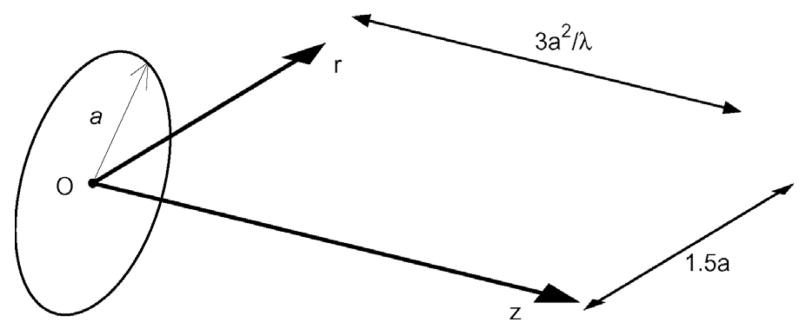
Fig. 1 contains a model of a circular piston and the coordinate system for transient pressure-field calculations. The radius of the piston is represented by a, and the nearfield pressure is evaluated in a linear, homogeneous medium characterized by the sound speed c and density ρ0. In Fig. 1, the radial coordinate is indicated by r and the axial coordinate is represented by z. In this cylindrical coordinate system, the transient pressure is computed for a time-varying normal velocity represented by v(t).
Fig. 1.
Coordinate axes and circular piston geometry defined for transient pressure field calculations.
B. Error Calculations
Transient pressure calculations are compared and evaluated through the difference in energy between the computed field and a reference field. This difference, which is computed as a function of space, defines the numerical error as:
| (1) |
where || · || denotes the L2 norm evaluated with respect to the time variable. The peak values of η(r, z) also are tabulated, and these are stored along with the computation times that are measured for each transient calculation method.
C. Rayleigh-Sommerfeld and Schoch Integrals
Several different analytical integral expressions describing the pressure generated by a circular piston are summarized in [6], and of these, the Rayleigh-Sommerfeld and Schoch integrals are particularly amenable to numerical evaluations for transient excitations. In cylindrical coordinates, the Rayleigh-Sommerfeld diffraction integral is a double integral represented by:
| (2) |
with . Through the cylindrical symmetry of R(ψ, σ), the integrand of (2) evaluated for ψ ∈ [0, π] is replicated for ψ ∈ [π, 2π], so the limits of integration are reduced to [0, π].
The Schoch integral [6] is defined as:
| (3) |
with θ1 = sin−1 (a/r) and:
| (4) |
| (5) |
for r > a. For r < a, the Schoch integral is:
| (6) |
with R2(θ) from (5). As in (2), the Schoch integral exploits the cylindrical symmetry of the pressure generated by a circular piston.
D. Impulse Response
For a circular piston, the impulse response is defined as:
| (7) |
where and:
| (8) |
Impulse response calculations convolve h(r, z; t) with the time derivative of the normal velocity v̇(t) at each grid point to obtain the pressure p(r, z; t) = v̇ (t) ⊗ h(r, z; t). Convolutions are performed with the fastest Fourier transform in the west (FFTW) library [7], and each result is evaluated with a fixed sampling rate throughout the entire spatial domain.
E. Fast Nearfield Method
Previously [4], four analytically equivalent expressions for the time-harmonic nearfield pressure generated by a circular piston were evaluated numerically, and the results demonstrated that the single-integral expression for the time-harmonic pressure:
| (9) |
yields superior numerical performance in terms of both speed and accuracy. Eq. (9) is the FNM single integral expression for the time-harmonic pressure generated by a circular piston. In (9), the delay times are represented by:
| (10) |
| (11) |
the wavenumber is related to the angular frequency by k = ω/c, and v̂ (ω) denotes the time-harmonic uniform normal velocity. The inverse Fourier transform of (9) yields the FNM time-domain expression:
| (12) |
which describes the nearfield pressure generated by a circular piston for all points (r, z) and all times t. The FNM expression in (12), unlike the Schoch integral or the impulse response, avoids numerical errors near r = a with a single expression that describes the nearfield pressure for all values of (r, z).
III. Time-Space Decomposition
A significant reduction in the computation time required for transient pressure calculations in the nearfield region is obtained by algebraically decoupling the temporal and spatial components of the FNM expression in (12). This decoupling is facilitated by the integrand of (12), which consists of the time-independent kernel function:
| (13) |
multiplied by the difference between the time-shifted normal particle velocities v(t − τ1) and v(t − τ2). The arguments of the latter two expressions depend on time through the variable t and on the spatial coordinate through τ1 and τ2. Through an appropriate selection of the input v(t), the temporal and spatial components of the time-shifted normal particle velocities also are decoupled. The result is a sum of single integral expressions that depend only on spatial variables. These integrals converge rapidly; therefore, each integral achieves a small error with a very small number of abscissas. Thus, the problem of calculating transient pressures in the nearfield region is converted into the superposition of a small number of single integral expressions that depend only on the spatial coordinate. This time-space decomposition approach, applied to the FNM single integral expression derived in [4], greatly accelerates the calculation of transient pressures in the nearfield for a circular source without increasing the numerical error.
Time-space decomposition is achieved for any continuous temporally windowed pulse:
| (14) |
with rect(t) = 1 if t ∈ [0, 1], and rect(t) = 0 otherwise. In (14), the spatial and temporal dependencies are strictly confined to the functions fn(τ) and gn(t), respectively. For example, time-space decomposition is obtained for the broadband pulse [8], [9]:
| (15) |
after the binomial theorem, laws of exponentiation, and trigonometric identities are applied to each of the corresponding terms in v(t − τ). The result is a sum of products of polynomial, exponential, sine, and cosine terms that define fn(τ) and gn(t) with N = 8 for (15). In the following simulations, the center frequency is f0 = 2.5 MHz, the temporal duration of the pulse is W = 1.2 μs, and the damping factor is β = 9.3750 μs−1.
In (12), the delays τ1 and τ2 are time-independent functions of the observation coordinates (r, z) and the integration variable ψ as defined in (10) and (11), which facilitates the extraction of the time dependence from the FNM integral in (12). After (12), (13), and (14) are combined, the summation and integration operations are exchanged, and the time-dependent gn(t) terms are moved outside of the integral, yielding:
| (16) |
In the first integral, the factor v(t − τ2) is also shifted outside of the integral since the delay τ2 = z/c is independent of ψ. Defining separate terms for each integral in (16) produces:
| (17) |
and:
| (18) |
Both En and D must be evaluated numerically with the same kernel function Ma(r, ψ) and the same number of abscissas; otherwise, a numerical singularity will appear on either side of the cylinder defined by r = a (as demonstrated for time-harmonic excitations in [4]). The integrals En in (17) describe the spatial variations of the edge wave components, whereas the integral D in (18) represents the direct wave contributions. In terms of En and D, (16) is:
| (19) |
The integrals En in (17) reduce to:
| (20) |
after the rect function is evaluated and equivalent limits of integration are substituted into the result. In (20), the lower limit ψ1(r, z; t) = 0 for t ∈ [t2, t2 + W] and:
| (21) |
for t ∈ [t2 + W, t3 + W], where the times t2 and t3 are defined in (8). Likewise, the upper limit ψ2(r, z; t) = π for t ∈ [t3, t3 + W ] and:
| (22) |
for t ∈ [t2, t3]. The limits of integration ψ1 and ψ2 specify the locations of the wavefronts emanating from the edge of the piston. For t ∈ (t2, t3), only the wavefronts emanating from angles ψ ∈ [0, ψ2) have reached the observation point (r, z). Likewise, for t ∈ (t2 + W, t3 + W), waves emanating from angles ψ ∈ [0, ψ1) already have passed (r, z); therefore, the lower limit of integration begins at ψ1. Thus, only the parts of the radiating surface that contribute to the pressure field at a certain observation point and time are included in the limits of integration.
Numerical calculations of the transient pressure field evaluate the integrals En and D with abscissas {αi : 1 ≤ i ≤ NGauss} and weights {wi : 1 ≤ i ≤ NGauss} defined for Gauss quadrature [10], [11]. The integral expressions for En in (20) contain multiple redundant calculations, and the redundancies are eliminated by calculating each repeated term only once. The results then are stored in N upper triangular matrices of size NGauss ×NGauss at each point in space (r, z). These upper triangular matrices, which replace the edge wave integrals En, are given by:
| (23) |
Each element in the matrix , 1 ≤ l ≤ m ≤ NGauss is recursively computed at a particular spatial location, and the upper and lower limits l = l(r, z; t) and m = m(r, z; t) are determined at each point in time. Because the functions gn(t) are independent of space, these values are precomputed then multiplied by the corresponding entry in . The resulting time-domain pressure is expressed as the weighted sum of N integrals:
| (24) |
This expression, which retains the rapid convergence of the FNM integral defined for time-harmonic pressure calculations, significantly accelerates computations of the transient nearfield pressure generated by a circular piston by extracting the time dependence from the FNM integral and by exploiting redundancies in the resulting edge wave expressions.
IV. Results
The Rayleigh-Sommerfeld integral, the Schoch integral, the impulse response convolution integral, and the FNM integral with time-space decomposition are evaluated numerically in the C programming language. All computations are performed on a 3.0 GHz Pentium IV (Dell, Inc., Round Rock, TX) computer with 3 GB of RAM running Red Hat Linux (Red Hat, Inc., Raleigh, NC), and each routine is called from within Matlab (The MathWorks, Natick, MA). The simulation packages Field II [12] and DREAM [13], which evaluate sampled versions of the impulse response, also compute transient pressures within Matlab. All simulations are evaluated in a medium with sound speed c = 1.5 mm/μs using the broadband pulse defined in (15).
A. Reference Field
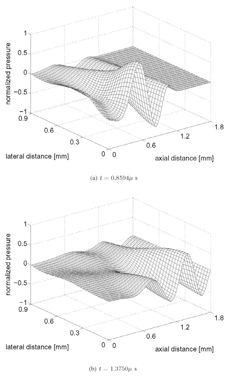
In Fig. 2, the Schoch integral in (3) and (6) generates the reference transient field for a circular piston with radius a = 0.6 mm. The transient field is evaluated with NGauss = 100, 000 abscissas for the f0 = 2.5 MHz input pulse described in (15) sampled at a rate of fs = 64 MHz. Figs. 2(a) and (b) depict two of the 178 time instances computed for the reference field at t = 0.8594 μs and t = 1.3750 μs, respectively. In Fig. 2, the nearfield pressure is calculated in the half-plane bounded by the lines r = 0 and z = 0, and the result is normalized with respect to the overall spatio-temporal peak value. The computational domain consists of 31 samples in the lateral direction extending from the center of the piston to 1.5 piston radii (or 0.9 mm) and 101 axial samples extending from the center of the piston out to three far-field transition distances (or 1.8 mm).
Fig. 2.
Simulated acoustic field produced by a circular piston with radius a = 0.6 mm. The Schoch integral, evaluated with 100,000 Gauss abscissas at each point in space and time, generates this reference field for an input pulse with a center frequency f0 = 2.5 MHz.
B. Spatial Error Distribution
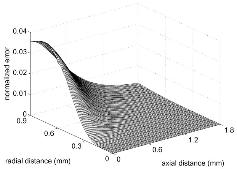
Fig. 3 displays the spatial error distribution computed for the time-space decomposition method evaluated with 6 Gauss abscissas. The time-space decomposition results are computed for 178 time samples on a 31 by 101 point spatial grid, then (1) calculates the normalized error η(r, z) by evaluating the norm of the difference between the reference waveform in Fig. 2 and the time-space decomposition result. For a circular piston with radius a = 0.6 mm, time-space decomposition applied to the FNM integral with NGauss = 6 achieves a peak error of 3.85% at (r, z) = (0.9, 0) mm. Fig. 3 also indicates that, for FNM calculations with (12), the error decays rapidly as the axial coordinate increases.
Fig. 3.
Normalized error distribution for the time-space decomposition method applied to the FNM integral in (12) evaluated with 6 Gauss abscissas. The peak error relative to the reference pressure depicted in Fig. 2 is 3.85%.
C. Times and Errors
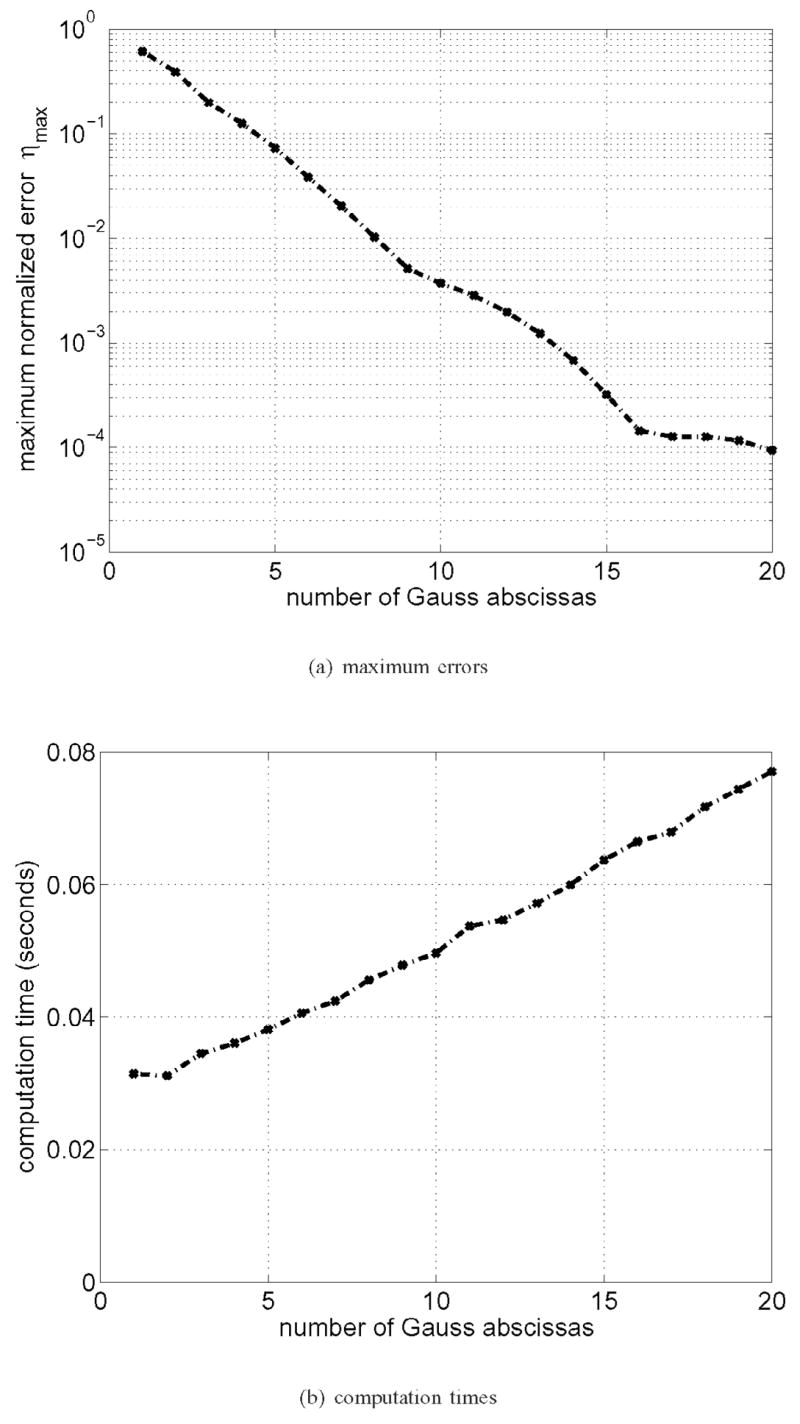
Fig. 4 summarizes the errors and and times computed for the time-space decomposition method. For these calculations, the temporal sampling of the computed pressure field is maintained at fs = 64 MHz, and the number of Gauss abscissas is varied from 1 to 20. In Fig. 4(a), the maximum normalized errors are presented in a semi-log plot in which the Gauss abscissas are displayed on the horizontal axis. Fig. 4(a) shows that the time-space decomposition method achieves a maximum 10% error with 5 Gauss abscissas for a piston of radius a = 0.6 mm. Fig. 4(b), which depicts the computation times on the vertical axis, indicates that time-space decomposition applied to the FNM integral achieves a 10% error in 0.050 seconds. Similarly, the time-domain method requires 9 abscissas to achieve a maximum error of 1% in 0.065 seconds. Fig. 4(a) shows that the convergence of the FNM integral is approximately exponential, and Fig. 4(b) indicates that the computation time increases linearly with respect to the number of Gauss abscissas.
Fig. 4.
(a) Numerical errors and (b) computation times for the time-space decomposition method plotted versus the number of Gauss abscissas for a circular piston with radius a = 0.6 mm.
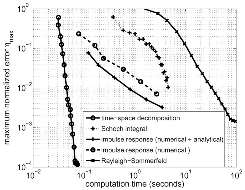
Fig. 5 combines the error and time plots of Figs. 4(a) and (b) and instead displays the error as a function of the computation time on a log-log scale. Results also are shown for the Schoch integral, the impulse response, and the Rayleigh-Sommerfeld integral. In Fig. 5, shorter computation times are located closer to the vertical axis on the left-hand side of the graph, and smaller errors are closer to the horizontal axis on the bottom of the graph. The smallest errors are achieved in the shortest time with time-space decomposition, and the Rayleigh-Sommerfeld integral generates the largest errors in the longest times. The results obtained with the impulse response and the Schoch integral are located between these two extremes.
Fig. 5.
Comparison of maximum normalized errors ηmax and measured computation times for the time-space decomposition method, the impulse response (numerical + analytical), the impulse response (numerical), the Schoch integral, and the Rayleigh-Sommerfeld integral. For a given maximum error value, time-space decomposition is significantly faster than each of the remaining methods.
In Fig. 5, the sampling frequency is varied logarithmically from 64 MHz to 2048 MHz for two impulse response calculation methods. The impulse response (numerical) directly samples (7) at all time points, then evaluates an FFT-based convolution of the entire impulse response. In contrast, the impulse response (numerical + analytical) performs an FFT-based convolution only for the portion of the impulse response that defines Ωa(r, z; t) for t ∈ (t2, t3), and the portion of the impulse response that is represented by a constant for t ∈ (t1, t2) in r < a is evaluated analytically. This eliminates the aliasing problem at the leading edge of the impulse response at t1 for r < a. By evaluating the analytical and numerical contributions separately, the peak numerical error also decreases, as evinced by the shift in the direction of smaller errors demonstrated for the impulse response (numerical + analytical) curve relative to the impulse response (numerical) plot in Fig. 5.
The errors and computation times obtained with each of these methods are compiled in Tables I and II for peak errors of 10% and 1%, respectively. In addition, impulse response calculations with the Field II [12] and DREAM [13] programs are also included. Each tabulated entry was generated in a script that increases the number of abscissas, sampling frequency, and/or number of subelements until the peak error drops below the threshold error value of 10% or 1%. Table I lists each of the methods starting with the slowest and ending with the fastest (i.e., the shortest computation time) for a 10% peak error. In Table II, the results are sorted with respect to a peak error of 1%. Table I shows that the Rayleigh-Sommerfeld and Schoch integrals are the slowest methods for a 10% peak error, the Field II and DREAM programs require the next longest computation times, then direct numerical computation of the impulse response achieves some improvement with respect to the previous methods, and the fastest of these for a 10% peak error is time-space decomposition applied to the FNM integral. Table II demonstrates that, for a 1% peak error, the time required for calculations with the Field II and DREAM packages increase significantly more than any of the other methods. In Table II, the Rayleigh-Sommerfeld integral, the DREAM package, and the Field II package are all more than 100 times slower than the time-space decomposition approach. The remaining methods, namely the Schoch integral, the impulse response (numerical), and the impulse response (numerical + analytical), are each at least 20 times slower than time-space decomposition.
TABLE I.
Measured Computation Times Corresponding to a Peak Error of 10% for the Rayleigh-Sommerfeld Integral, Schoch Integral, Field II, DREAM, the Impulse Response (Numerical), the Impulse Response (Numerical + Analytical), and Time-Space Decomposition Applied to the FNM Integral.
| Method | Input parameters | Computation time (seconds) | Time required relative to time-space decomposition |
|---|---|---|---|
| Rayleigh-Sommerfeld | 49 abscissas | 13.0356 | 343x |
| Schoch | 10 abscissas | 2.3378 | 61x |
| DREAM | 225 elements at 128 MHz | 1.1079 | 27x |
| Field II | 208 elements at 128 MHz | 0.6850 | 18x |
| Impulse response (numerical) | 256 MHz | 0.2434 | 6x |
| Impulse response (numerical + analytical) | 64 MHz | 0.1218 | 3x |
| Time-space decomposition | 5 abscissas | 0.0381 | — |
TABLE II.
Measured Computation Times Corresponding to a Peak Error of 1% for the Rayleigh-Sommerfeld Integral, Schoch Integral, Field II, DREAM, the Impulse Response Method (Numerical + Analytical and Numerical), and Time-Space Decomposition Applied to the FNM Integral.
| Method | Input parameters | Computation time (seconds) | Time required relative to time-space decomposition |
|---|---|---|---|
| Rayleigh-Sommerfeld | 121 abscissas | 32.1521 | 844x |
| DREAM | 40,000 elements at 1024 MHz | 12.8355 | 269x |
| Field II | 3,480 elements at 512 MHz | 8.9723 | 188x |
| Schoch | 20 abscissas | 4.5396 | 95x |
| Impulse response (numerical) | 2048 MHz | 2.6999 | 56x |
| Impulse response (numerical + analytical) | 512 MHz | 0.8127 | 17x |
| Time-space decomposition | 9 abscissas | 0.0478 | — |
V. Discussion
A. Evaluation of Computation Times and Numerical Errors
Of the methods evaluated in Fig. 5 and Table I, the Rayleigh-Sommerfeld integral requires the most time to achieve a 10% maximum error. This is in part due to the large number of abscissas required to perform the double integration and in part due to the slow convergence of (2). The Rayleigh-Sommerfeld integral produces particularly large errors at all observation points near the piston surface; therefore, the grid coordinates were offset by one-half wavelength along the z axis for all pressure calculations with (2). Even with the axial offset, large numerical errors are nevertheless encountered close to the piston face.
The Schoch integral is a single integral expression that converges more rapidly than the Rayleigh-Sommerfeld integral. Thus, for a 10% or a 1% maximum error, the computation time is reduced relative to the Rayleigh-Sommerfeld integral. The largest errors with the Schoch integral occur near r = a, and these errors are responsible for the slow convergence relative to the impulse response and time-space decomposition applied to the FNM integral.
The Field II and DREAM programs converge more rapidly than the Schoch integral for a 10% maximum error, but the rate of convergence decreases for smaller errors. Field II and DREAM converge slowly and generate large numerical errors in the region near the piston surface; therefore, Field II and DREAM computations were axially offset by one-half wavelength. For a 10% maximum error, the FFT achieves some reduction in the computation time for transient nearfield pressure calculations with these programs relative to the Rayleigh-Sommerfeld and Schoch integrals. However, for a maximum error of 1%, the advantage of the FFT is offset by the higher spatial and temporal sampling rates required. As a result, both the Field II and DREAM programs exceed the time required to numerically evaluate the Schoch integral, and these programs approach the computation time and numerical error of the Rayleigh-Sommerfeld integral. However, both FIELD II and DREAM possess convenient user interfaces that reduce the time required for programming, which is useful for many applications.
Direct evaluations of the impulse response are consistently faster than the Field II and DREAM packages for this geometry. For a 10% maximum error, the impulse response (numerical) and impulse response (numerical + analytical) methods are 3 to 9 times faster than Field II and DREAM; and for a 1% peak error, the impulse response (numerical) and impulse response (numerical + analytical) methods are 4 to 16 times faster than these two packages. Because both FIELD II and DREAM approximate the aperture with rectangular subelements, the resulting fields suffer from geometric modeling errors [14]. A more efficient approach for a circular aperture uses the analytical impulse response function in (7). However, the impulse response (numerical) approach produces large on-axis errors. Thus, a sampling frequency of fs = 256 MHz is required for a 10% maximum error and a sampling frequency of fs = 2048 MHz is required for a 1% maximum error. The numerical error, the sampling rate, and the computation time are all markedly reduced in calculations that analytically evaluate the on-axis portion of the impulse response function and numerically compute the off-axis portion with the FFT. The analytical component consists of two terms that correspond to the delays t1 and t2 in (8), and in particular, the t1 term is evaluated with code extracted from the time-space decomposition routine that avoids duplicate calculations that otherwise occur in the direct wave contribution to the overall solution. Thus, the impulse response (numerical + analytical) combines a portion of the direct wave solution obtained from the time-space decomposition approach with another analytical calculation and an FFT-based convolution, thereby reducing the sampling rates to fs = 64 MHz and fs = 512 MHz for maximum errors of 10% and 1%, respectively. The reductions in the sampling rates achieved by the impulse response (numerical + analytical) method are accompanied by corresponding decreases in the computation time relative to the impulse response (numerical) approach for a specified peak error value as indicated in Tables I and II.
As shown in Fig. 5 and Tables I and II, the time-space decomposition approach of (24) consistently achieves the shortest computation times for a specified peak error value. The time-space decomposition results demonstrate a maximum error of 10% with 5 Gauss abscissas for this piston geometry, and only 9 Gauss abscissas are required for a maximum error of 1%. Furthermore, the computation time is reduced by factors of 3 and 17 for maximum errors of 10% and 1%, respectively, relative to the impulse response (numerical + analytical), which is the fastest implementation of the impulse responses evaluated for a single piston source. Tables I and II also show that time-space decomposition reduces the computation time by one or two orders of magnitude with respect to the Rayleigh-Sommerfeld integral, the Schoch integral, and the Field II and DREAM programs. In addition, the FNM integral in (12) and the time-space decomposition expression in (24) converge much more rapidly than any of these other methods. As a result, the maximum numerical error obtained with these expressions is consistently smaller than that generated by these other methods. This suggests that (12) and (24) provide ideal references for transient nearfield computations. For example, the maximum error of the reference pressure field computed with NGauss = 100, 000 applied to the Schoch integral is on the order of ηmax = 1 × 10⁻⁸, and this is approximately the same error obtained with 300 Gauss abscissas applied to (12) or (24). The results also show that, although the impulse response elicits some reduction in the computation time from the FFT, the impulse response is fundamentally limited by the rapid changes in h(r, z; t) that correspond to the onset of the arriving pulse and the edges of the radiating piston. This limitation offsets the main advantage of FFT-based impulse response calculations. Unlike the integrand of the impulse response convolution integral, the integrands of (12) and (24) inherently remain smooth throughout the computational grid, and the sampling and aliasing problems of the impulse response are automatically eliminated by these expressions. Thus time-space decomposition, which converts the numerical evaluation of transient pressures in the nearfield region into the superposition of a small number of spatial integrations that exploit repeated calculations, exhibits faster convergence and shorter computation times than the impulse response and other analytical methods for transient pressure calculations in the nearfield region.
B. Memory Requirements
Time-space decomposition results in more efficient memory management than the impulse response, which requires an artificially large sampling frequency to reduce aliasing errors. At each point in space, the impulse response method performs an FFT of length Ns = Δtfs, where Δt = 2a/c + W is the maximum length of the excitation signal. Additional zero-padding prevents the wrap-around errors associated with circular convolution. To achieve a maximum error of 1%, the impulse response (numerical + analytical) uses a temporal sampling rate of fs = 512 MHz, and 1024 memory locations are required for simulations with this combination of parameters.
In contrast, time-space decomposition constructs N upper-triangular matrices of size NGauss × NGauss, where N is the number of terms in the pulse expansion given by (14). Therefore, the memory requirement scales as N NGauss(NGauss + 1)/2, or 4NGauss(NGauss + 1) for the broadband pulse defined by (15). To achieve a maximum error of 1%, NGauss = 9, so 360 memory locations are required. Thus, time-space decomposition reduces the memory required by a factor of 2.8 relative to the impulse response. This efficient handling of memory is especially important for large-scale, phased-array simulations, which can use hundreds or thousands of elements spanning tens or hundreds of wavelengths in each direction.
C. Other Excitation Pulses
Time-space decomposition also was evaluated with a three-cycle toneburst and a Hanning-weighted excitation. For both of these inputs, similar improvements were again obtained relative to the other methods evaluated for 10% maximum error and 1% maximum error. For example, a short toneburst only requires N = 2 terms, thus time-space decomposition converges to 10% maximum error in only 0.033 seconds and 1% maximum error is reached in 0.0397 seconds. The other methods also compute transient results in times similar to those listed in Tables I and II. Comparable results also are obtained for a short Hanning-weighted pulse.
D. Applications to Imaging and Therapy
The time-space decomposition technique is intended for simulations of large ultrasound phased arrays designed for diagnostic and therapeutic applications. Because these ultrasound phased arrays consist of a large number of elements, the time-space decomposition technique also is appropriate for simulations of these and other apertures. Once the incident field is computed, the backscattered signal and received RF traces can be simulated by solving a forward scattering problem.
The time-space decomposition method also is applicable in conjunction with first-order scattering models or other solvers that use fast integral methods [15] or k-space methods [16]. This combination of fast and accurate tools for finding incident and scattered fields can aid in the design and evaluation of transducer array geometries.
VI. Conclusions
Time-space decomposition applied to the FNM integral for a circular piston achieves a substantial reduction in the time required to compute the transient nearfield pressure relative to the impulse response and other analytical integral methods. This approach analytically separates the spatial and temporal characteristics of the integrand and the input pulse so that, for the pulse evaluated here, N = 8 spatial integrals are computed then weighted with time-dependent factors. The results show that, for maximum errors of 10% and 1%, the time-space decomposition approach is at least one or two orders of magnitude faster than the Rayleigh-Sommerfeld integral, the Schoch integral, the Field II simulation package, and the DREAM simulation package. For uniformly sampled impulse response (numerical) calculations that directly evaluate the convolution integral with the FFT, time-space decomposition reduces computation times by factors of 6 and 56 for maximum errors of 10% and 1%, respectively. The impulse response (numerical + analytical), which is the fastest impulse response method evaluated, reduces the computation time by evaluating analytical expressions for the direct wave component and by exploiting some features of the time-space decomposition approach. By separating the impulse response into numerical and analytical calculations, the sampling rate for FFT-based convolutions of the edge wave component is also reduced. Despite these enhancements, the time-space decomposition is more than three times faster than the impulse response (numerical + analytical) for a 10% maximum error and 17 times faster for a 1% maximum error.
Time-space decomposition avoids the aliasing problems associated with the impulse response method, and by exploiting the repeated calculations in the resulting spatial integrals, the computation times and numerical errors are dramatically reduced. The results demonstrate that time-space decomposition achieves a significant time savings in these calculations, which use a small number of Gauss abscissas instead of the FFT. As demonstrated in Fig. 5 and Tables I and II, the numerical convergence of (24) and the FNM integral in (12) is superior to the impulse response and the other analytical integrals evaluated. Thus, the numerical errors are smaller with time-space decomposition and the FNM integral, which suggests that (24) and (12) are eminently ideal for reference calculations of transient nearfield pressures. Moreover, the excessive sampling frequencies associated with the impulse response are eliminated with time-space decomposition, which requires significantly less memory than the impulse response. Thus, memory management is greatly improved with the time-space decomposition approach. These enhancements will accelerate future computer simulations of ultrasound therapy and imaging.
Acknowledgments
The authors thank Xiaozheng Zeng, Shanker Balasubramaniam, and Liyong Wu of the Department of Electrical and Computer Engineering at Michigan State University for helpful comments and thoughtful discussions.
This work was funded in part by NIH grant 5R01CA093669.
Biographies
James F. Kelly was born in Montclair, NJ on June 17, 1979. He received his B.S. degree in Applied Mathematics from Pennsylvania State University in 2001 and his M.S. degree in Industrial Mathematics from Michigan State University in 2005.
He is currently a doctoral student in Electrical and Computer Engineering at Michigan State University, where his research focuses on numerical modeling of diagnostic and therapeutic ultrasound.
He is a student member of the Society for Industrial and Applied Mathematics.

Robert J. McGough (S’87–M’87) was born in Hinsdale, IL on October 1, 1965. He received the B.E. degree (summa cum laude) in electrical engineering and physics from Vanderbilt University in 1987, the M.S. degree in electrical engineering from the University of Illinois in Urbana-Champaign in 1990, and the Ph.D. degree in electrical engineering from the University of Michigan in Ann Arbor in 1995.
He is currently an Assistant Professor at the Department of Electrical and Computer Engineering at Michigan State University. His research interests combine ultrasound phased array systems and hyperthermia. He is a member of IEEE and the North American Hyperthermia Society.

Footnotes
Field II version 2.86 for MATLAB, http://www.es.oersted.dtu.dk/sta3/jaj/field/index.html
DREAM version 1.1 for MATLAB, http://www.signal.uu.se/Toolbox/dream/
References
- 1.Oberhettinger F. On transient solutions of the ‘baffled piston’ problem. J Res Nat Bureau Standards-B Math Math Phys. 1961;65B(1):1–6. [Google Scholar]
- 2.Stepanishen PR. Transient radiation from pistons in an in-finite planar baffle. J Acoust Soc Amer. 1971;49(5):1629–1638. [Google Scholar]
- 3.Lockwood JC, Willette JG. High-speed method for computing the exact solution for the pressure variations in the nearfield of a baffled piston. J Acoust Soc Amer. 1973;53(3):735–741. [Google Scholar]
- 4.McGough RJ, Samulski TV, Kelly JF. An efficient grid sectoring method for calculations of the nearfield pressure generated by a circular piston. J Acoust Soc Amer. 2004;115(5):1942–1954. doi: 10.1121/1.1687835. [DOI] [PMC free article] [PubMed] [Google Scholar]
- 5.McGough RJ. Rapid calculations of time-harmonic nearfield pressures produced by rectangular pistons. J Acoust Soc Amer. 2004;115(5):1934–1941. doi: 10.1121/1.1694991. [DOI] [PMC free article] [PubMed] [Google Scholar]
- 6.Harris GR. Review of transient field-theory for a baffled planar piston. J Acoust Soc Amer. 1981;70(1):10–20. [Google Scholar]
- 7.Frigo M, Johnson SG. FFTW: An adaptive software architecture for the FFT. Proc IEEE Int Conf Acoust, Speech, Signal Proc. 1998;3(1):1381–1384. [Google Scholar]
- 8.Denisenko N, Scarano G, Matteucci M, Pappalardo M. An approximate solution of the transient acoustic field. IEEE Trans Ultrason, Ferroelect, Freq Contr. 1985;46(6):821–827. [Google Scholar]
- 9.San Emeterio JL, Ullate LG. Diffraction impulse-response of rectangular transducers. J Acoust Soc Amer. 1992;92(2):651–662. [Google Scholar]
- 10.Davis PJ, Rabinowitz P. Methods of Numerical Integration. New York: Academic; 1975. pp. 139–140. [Google Scholar]
- 11.Abramowitz M, Stegun IA. Handbook of Mathematical Functions, with Formulas, Graphs, and Mathematical Tables. New York: Dover; 1972. pp. 887–889.pp. 916–919. [Google Scholar]
- 12.Jensen JA, Svendsen NB. Calculation of pressure fields from arbitrarily shaped, apodized, and excited ultrasound trans-dcuers. IEEE Trans Ultrason, Ferroelect, Freq Contr. 1992;39:262–267. doi: 10.1109/58.139123. [DOI] [PubMed] [Google Scholar]
- 13.Piwakowski B, Sbai K. A new approach to calculate the field radiated from arbitrarily structured transducer arrays. IEEE Trans Ultrason, Ferroelect, Freq Contr. 1999;46(2):422–440. doi: 10.1109/58.753032. [DOI] [PubMed] [Google Scholar]
- 14.Oung H, Forsberg F. Geometric and algebraic errors in calculating a transducer’s spatial impulse response. IEEE Trans Ultrason, Ferroelect, Freq Contr. 1996;43(2):337–340. [Google Scholar]
- 15.Ergin AA, Shanker B, Michielssen E. Fast transient analysis of acoustic wave scattering from rigid bodies using a two-level plane wave time-domain algorithm. J Acoust Soc Amer. 1999;106(5):2405–2416. doi: 10.1121/1.428406. [DOI] [PubMed] [Google Scholar]
- 16.Mast TD, Souriau LP, Liu DL, Tabei M, Nachman AI, Waag RC. A k-space method for large-scale models of wave propagation in tissue. IEEE Trans Ultrason, Ferroelect, Freq Contr. 2001;48(2):341–354. doi: 10.1109/58.911717. [DOI] [PubMed] [Google Scholar]


