

Abstract
Thermal stress development in blood vessels, during processes associated with vitrification (vitreous means glassy in Latin), is studied. This paper addresses the limiting case where the specimen completely crystallizes, while the cryoprotectant medium (CPA) completely vitrifies. This case is expected to provide upper boundary estimates for stresses for the more common problem of a partially vitrified sample. The CPA is modeled as a linear viscoelastic medium, with viscosity increasing exponentially with decreasing temperature; given the assumption of complete crystallization, the blood vessel is modeled as linear elastic below the freezing temperature. Consistent with previous observations, the CPA is found to behave linear elastically below a set-temperature, at which point the viscosity rises sufficiently quickly with further cooling. This observation reduces computational efforts and allows for parametric studies based on suitably chosen wholly elastic models. Both 2D concentric cylinder models of the blood vessel in a straight configuration and a 3D model of the vessel curled in a vial of CPA are studied; 2D models are shown to bound the results of the more general 3D problem. It is found that stress in the CPA decreases with increase in CPA volume, at least under conditions where the temperature can be viewed as uniform. Planar cracks are predicted to form transverse to the vessel axis, and to propagate right up to the blood vessel wall. Should such cracks propagate into the vessel, even over only a few μm, the mechanical damage to the lumen, or to endothelial cells, may cause the blood vessel to completely loose its functionality at the end of the cryopreservation protocol.
Keywords: Vitrification, Solidification, Solid Mechanics, Thermal Stress, Blood Vessels, Set Temperature
Introduction
In the present era of arterial replacement, at least 345,000 to 485,000 autologous coronary grafts [1,2] (either arteries or veins) and over 200,000 autogenous vein grafts into peripheral arteries are performed each year [3]. A recent marketing report indicated that at least 300,000 coronary artery bypass procedures are performed annually in the USA, involving in excess of 1 million vascular grafts [4]. Many of these patients do not have autologous veins suitable for grafts due to pre-existing vascular disease, vein stripping, or use in prior vascular procedures. It has been estimated that as many as 30% of the patients who require arterial bypass procedures will have saphenous veins unsuitable for use in vascular reconstruction [5].
In recent years, an increasing and sometimes urgent need has emerged for alternative blood vessel substitutes, when autologous blood vessels are not available and in circumstances where synthetic graft materials are usually unsatisfactory. Tissue engineered blood vessels (TEBV) offer potential alternative vascular grafts for autologous transplantation. However, the long culture period required for vessel construction represents a potential limitation for use of this technology (typically, 8 to 10 weeks). If engineered vessels could be constructed ahead of their anticipated clinical need and stored for later use, the clinical utility of this new technology might be greatly enhanced. TEBV may provide an alternative approach for the estimated 30% of patients requiring arterial bypass procedures for whom no suitable autologous graft materials are available. Tissue engineering technology is believed to have the potential to produce the “next generation” of biological grafts for use in both vascular and cardiac surgery.
Since the advent of transplantation science, cryopreservation has been recognized as a highly desirable method for facilitating availability of the highest quality material. This goal has been achieved in some cellular systems, but extrapolation to organized tissues and organs is fraught with additional problems that have only recently been addressed. Application of the principles of cryobiology to the growing needs of the emerging tissue engineering field--with TEBV as an example--has emphasized the need for greater understanding of the fundamentals of low temperature preservation as they apply to three-dimensional multi-cellular tissues. An understanding of the thermo-mechanical stresses inherent to cryopreservation of complex biological systems is crucial for the development of improved methods of storage. This important aspect of cryobiology has thus far received little attention, whereas the basic tools necessary for the study of these fundamental problems have not been available. The current study represents another step in an ongoing effort to analyze and quantify thermal stress effects in cryopreservation, with application to blood vessel storage.
Classical cryopreservation using low concentrations of cryoprotectants (CPAs) has been shown to conserve many important properties of vascular allografts. However, the techniques developed for freezing vascular allografts are not reliable. Fractures have been observed in cryopreserved arteries [6,7]. Nataf et al.[8] found that the contractile responses of both cryopreserved sheep carotid arteries and human internal mammary arteries were abolished. Studies on the endothelial and smooth muscle function in canine internal mammary arteries, using an eight-step protocol, demonstrated that smooth muscle functions were poorly preserved after cooling below −12°C [9]. Similar observations have been made in the recent studies of human arteries. Cryopreserved human internal mammary arteries and femoral arteries had both poorly preserved smooth muscle functions and endothelial functions [10,11]. Freeze substitution of cryopreserved blood vessels demonstrates high levels of extracellular ice formation [12,13]. There have been several hypotheses on mechanisms of freezing-induced injury based upon a variety of factors [14,15], but it has been suggested that the disadvantages of traditional cryopreservation revolve primarily around ice formation [16,17].
Vitrification (glass formation) is an alternative to conventional freezing of biological materials with ubiquitous applications in cell, tissue, and organ storage. Here, the effect of increased viscosity of the cryoprotectant with decreasing temperature is utilized with the application of high cooling rates. If the typical time scale to form crystals is exceeded by the typical time scale of cooling to cryogenic temperatures, the cryoprotectant solution may reach an “arrested liquid state” known as glass. No appreciable degradation occurs over time in living matter trapped within a vitreous matrix, and vitrification is potentially applicable to all biological systems. However, vitrification is associated with higher concentration of cryoprotectants, which are potentially very toxic, and cryoprotective cocktails are currently studied by various research groups to overcome this obstacle. Other difficulties with vitrification are known to be associated with uniform loading of the tissue with the cryoprotectant solution; these difficulties are more relevant to bulky specimens, and are related to scale up studies of vitrification.
Modeling of Stress and Relevance of Current Study
The current study is part of a long-term effort to develop engineering tools for predicting the propensity for cracking to occur in contemplated cryopreservation protocols. Predictions of cracking rely on calculations of mechanical stress, which is dependent upon a host of factors, including the cooling and warming protocols, the geometry of the specimen, the geometry of the surrounding CPA, and on the physical properties of the specimen and CPA. The properties of the specimen are further coupled with the properties of the pure CPA through the amount of CPA that permeates into the tissue. The concentration of the permeated CPA plays a key role in determining the tendency of the specimen-CPA system to vitrify, crystallize, or a combination thereof.
In contrast to the approach typical of biology studies, the common engineering approach attempts to identify, and possibly isolate, the key mechanisms dominating the phenomenon. Once identified, each mechanism is investigated independently, often with the goal of developing a mathematical model to predict its effect. As appropriate, models for multiple mechanisms may be combined into a more comprehensive model. Stresses during cryopreservation can be attributed to two distinct mechanisms associated with thermal expansion: temperature gradients, brought about by high cooling and/or warming rates, in a domain with homogeneous thermal expansion coefficient, and differences in thermal expansion coefficient between tissues and pure CPA at uniform temperature. The current paper addresses the second effect, which produces stresses regardless of the cooling rate; thus, the effect of cooling rate does not emerge from this study. As shown in previous work with CPA vitrifying on substrates and in vials [18-20], the change in viscosity plays a significant role. Stresses due to thermal expansion difference between CPA and the substrate or vial only begin to rise at temperatures approaching glass transition, when the viscosity is very high. These stresses can rise because the plate or vial themselves are solid and stiff throughout the cooling protocol.
By analogy with the case of CPA and a substrate, stresses can arise due to difference in thermal expansion between CPA and a blood vessel, particularly when the blood vessel crystallizes; such stresses are addressed in the current paper. In particular, the current study explores the special case in which the blood vessel fully crystallizes, while the CPA vitrifies. Cryomacroscopy studies of blood vessels cooled in a vial of CPA, indeed, found a range of intermediate cooling rates at which the CPA vitrifies and the blood vessel crystallizes. That range is associated with either lower concentration of CPA, or with slower cooling rate. Furthermore, the actual degree of crystallization in tissues varies in practice, likely spanning the range from full vitrification to a high degree of crystallization; the greater the extent of crystallization in the tissue, the more accurate will be predictions of stress given here. The predictions of stress in the current study arguably provide upper limits to the expected stress due to this mechanism for two major reasons: the fully crystallized material will behave as a solid for a greater portion of the cooling protocol, as compared with vitrified material, and literature data [21-23] indicates that the thermal expansion mismatch between fully crystallized tissue and CPA is significantly greater than the mismatch between vitrified tissue and CPA.
Direct comparison of predictions of the current work with existing experimental studies is not possible, although, perhaps, the most closely related work is the empirical study of the effect of cooling and warming protocols on fracture formation in the rabbit common carotid artery [7]. In that study, however, the constraining effect of the specimen holder on the specimen response during cooling is uncertain and could be overwhelming. In addition, possible temperature gradients in that study introduce another mechanism of stress generation, which is set aside in the current study. By contrast, the analyses to be conducted in this paper treat the artery and cryoprotectant as externally unconstrained.
Mathematical Formulation
In this section, the geometry of the mathematical problem is described first, and the material model and properties are addressed next. Two basic cases of stress development during cooling are presented in this study: a straight long blood vessel (Fig. 1), and a curved blood vessel placed in a storage vial and covered with cryoprotectant (Fig. 2). The case of a long straight blood vessel is modeled as an axi-symmetric concentric cylinder, permeated with CPA, and subject to three possible scenarios: the internal space is filled with CPA (Fig. 1(b)), only a film of CPA covers its internal wall (Fig. 1(c)), and the blood vessel is filled with CPA and immersed in a larger cylindrical domain of the same CPA (Fig 1(d)). The blood vessel is assumed to have an inner radius, R1, of 2 mm, an outer radius, R2, of 3 mm, and a length of 50 mm. The same radii are assumed for the curved blood vessel case in the vial (Fig. 2), where the CPA is now assumed to be a cylindrical domain, having a height of 7 mm and a radius of 12.5 mm; this 3D domain corresponds to a 15 ml vial filled to 3.4 ml, which includes the CPA and the blood vessel [18]. The centerline of the curved blood vessel forms a 270° arc of a radius of 7.5 mm, and the blood vessel is centered about the center of cylindrical domain. The various geometries depicted in Figures 1b, 1c, and 1d approximate achievable scenarios, such as described in the various experimental conditions in [7]. In all cases, the analysis models a thermo-mechanical stress problem with a constant cooling rate applied to the outer surface of the domain. The domain is assumed to be free of external forces, and a condition of continuity in displacement (no slip) is assumed at the interface between the blood vessel and the CPA.
Figure 1.

Schematic illustration of the 2D, axi-symmetric problem of a straight long blood vessel: (a) an isometric view of the baseline configuration, (b) a cross section of the same baseline configuration presented in (a), (c) partially filled blood vessel with CPA, and (d) blood vessel filled and surrounded by a cylindrical domain of CPA.
Figure 2.

Schematic illustration of the 3D problem of a curved blood vessel, completely immersed in CPA; the centerline of the blood vessel forms a 270° arc, having a diameter of 15 mm. The blood vessel inner and outer radii are 2 mm and 3 mm, respectively, and the CPA domain height is 7 mm.
As described above, a limiting case of solidification is assumed in this study, where the blood vessel completely crystallizes; this represents the limit of partial crystallization in which stresses are assumed to be highest. The surrounding and contained CPA are assumed to vitrify perfectly. (Another extreme case, where the blood vessel completely vitrifies is being currently investigated). The focus in this study is on the influence of differences in properties of the crystallized blood vessel and the vitrified CPA on stresses. Accordingly, a low cooling rate is considered; the resulting temperatures are more uniform, reducing any stresses associated with spatial variations in thermal strain (which requires a separate study). Vitrification of the CPA is justified if the cooling rate is initially rapid down to a sufficiently low temperature to avoid crystallization, with a relatively low cooling rate thereafter. In the extreme scenario envisioned here, the prevailing cooling rates and the kinetics are presumed insufficient to prevent crystallization in the blood vessel [24], but sufficient to promote vitrification in the pure CPA, where nucleation sources are absence, and the concentration is unaffected by the pre-existence of biological solutions. In particular, a cooling rate of 1°C/min is assumed to prevail. Detailed analysis of temperature distributions using typical thermal properties revealed that the maximum temperature variation (for all geometries considered) does not exceed 1°C. Therefore, all calculations of stresses are based on the assumption of a spatially uniform distribution of temperature.
Consistent with the assumption that the blood vessel fully crystallizes, its mechanical response is modeled as linear-elastic. This is further simplified to be isotropic, with an elastic modulus EBV and Poisson's ratio νBV. Since the properties of the frozen material are not known, it is not worthwhile to include anisotropy which may be present in the blood vessel. With decreasing temperature, the vitrifying CPA transitions from a liquid to a solid-like material. As suggested previously [19], the CPA is modeled as a simple viscoelastic fluid, with the viscosity taken to be an exponential function with decreasing temperature [21]. In uniaxial tension, the viscoelastic law takes the form:
| (1) |
where ε̇ is the strain rate, σ is the stress, ECPA is the CPA Young's modulus, η is the shear viscosity, and βCPA is the coefficient of thermal expansion of the CPA. This model describes the total strain-rate as a linear superposition of (from left to right in Eq. (1)) the elastic strain-rate, the viscous (or creep) strain-rate, and the thermal strain-rate [26]. The uniaxial stress-strain behavior is generalized to multi-axial stresses assuming an isotropic response, including Poisson ratio νCPA.
While making an effort to keep the study as broad as possible, the material properties selected in this study correspond to DMSO, which is a well studied CPA, and is the key ingredient in many CPA cocktails. More specifically, a concentration of 7.05M DMSO is selected as a reference, which has shown to have similar physical properties to those of the CPA cocktails DP6 and VS55 [21]. The 7.05M DMSO solution is considered very toxic, where the objective in developing CPA cocktails is reducing toxicity effects [12]. Nevertheless, the conclusions presented in the current study are very general, and the discussion below emphasizes the generality of the current findings.
The representative material properties used in this study are listed in Table 1. The thermal expansion of the CPA and the crystallized blood vessels are adopted from [22-23]. The Poisson ratios are typical of brittle materials [27] and the elastic moduli are typical of organic materials [28]; all are taken to be independent of temperature. The authors are unaware of measurements of these elastic properties at cryogenic temperatures. The impact of the ratio of EBV/ECPA is further discussed below.
Table 1.
Parameters used for analysis of CPA and blood vessel
| β×106, °C−1 | N | E, GPa | |
|---|---|---|---|
| Artery | 0.2916T + 63.76 [22] | 0.2* [27] | 1* [28] |
| 7.05M DMSO | 0.5634 T +208.4 [22] | 0.2* [27] | 1* [28] |
Typical value
The viscosity of DMSO at various molar concentrations has been measured in the temperature range of 20°C to −45°C with falling ball viscometry [25]; the authors are unaware of viscosity measurements of DMSO at lower temperatures. The viscosity of DMSO in the temperature range of interest (in the vicinity of the glass transition temperature, Tg) is orders of magnitude higher than that in the range of available experimental data [25]. While Tg is commonly measured with differential calorimetry techniques (DSC), an alternative definition of glass transition is the temperature at which the viscosity reaches a value of 1012 Pa-s (1013 Poise). In the absence of viscosity data at low temperatures, the following functional behavior is assumed in the current study [25]:
| (2) |
Parameters b = 8.607 K and T0 = −162.1°C are selected to best-fit the available experimental data at higher temperatures [20], and glass transition temperature was taken to be −132°C, measured with DSC for DMSO [21].
Calculations were performed with the general purpose finite element program, ANSYS 8.1. For the baseline axi-symmetric geometry (Fig. 1), 800 eight-noded axi-symmetric elements of type Plane183 were used to model the stresses in the CPA, and 400 elements of the same type were used to model the blood vessel. Symmetry conditions were applied to model only the upper half of the blood vessel and the CPA domain. The mesh was adapted as appropriate for the other axi-symmetric configurations. In the 3D case, Fig. 2, the finite element model consisted of 9837 twenty-noded SOLID186 brick elements. As explained below, some of the calculations were performed with both the blood vessel and the CPA taken to be purely elastic.
In calculations that account for the viscous deformation, special steps were taken to accommodate the variation in viscosity over many orders of magnitude within the simulated temperature range. During initial cooling from room temperature, when the viscosity is low, impractically small time steps would be required to ensure stability of simulation (on the order of 10−10 s). Likewise, the viscosity function well below glass transition is clearly incorrect. To overcome these problems, a piecewise viscosity function is assumed, where the viscosity is represented by Eq. (2) in the temperature range from −112°C to −141°C, corresponding to the viscosity values from 3×10⁵ Pa-s to 1020 Pa-s, respectively; the viscosity remains constant at a value of 3×10⁵ Pa-s at higher temperatures, and constant at a value of 1020 Pa-s at lower temperatures. This simplification leads to higher predicted stress at high temperatures; however, the stress level at these temperatures is orders of magnitude lower than the stress level believed to be associated with cracking. At low temperatures on the other hand, the viscosity value is so high that the material response is virtually elastic; the effect of limiting the viscosity value to 1020 Pa-s is, therefore, negligible.
Results and Discussion
At high temperatures, well above Tg, stresses are negligible everywhere, when compared with the strength of the material. Differences in thermal expansion are accommodated by viscous flow in the CPA, which readily occurs when the viscosity is low. As the viscosity rises, the stresses rise. Figure 3 displays results for the baseline case (Fig. 1(b)), where the stresses at the center of the CPA domain, and midway across the blood vessel wall (0.5 mm from either surfaces), are plotted as functions of temperature. The stresses continue to change essentially linearly with temperature below temperatures shown in the plot. Slight deviations from linearity are associated with very small changes in the thermal expansion coefficients. As has been noted recently in other situations featuring the cooling of vitrifying materials [19,20], stresses are negligible down to a “set-temperature”; below this temperature, cooling increases stress as could be expected from a linear elastic material.
Figure 3.

Variation of stress components with temperature at the center of the CPA and the center of the blood vessel wall, for the baseline concentric cylinder model, Fig. 1(b).
The set-temperature is defined as the temperature reached by linear extrapolation from the stress curve at lower temperatures to zero stress. It can be seen from Fig. 3 that the set-temperature differs by several degrees between the different stress components. As shown in [20], it is at this temperature that the CPA response is midway through the transition from being viscously dominated to being elastically dominated. The stresses in the CPA were found to be essentially uniform over most of the blood vessel length. As expected, within approximately 3 mm from the free ends of the blood vessel (less than 10% of its length), stresses start to fall below 90% of the maximum values presented in Fig. 3, towards a zero stress value at the free ends of the blood vessel (where zero force conditions are imposed).
The variation of the three stress components of the baseline case, as a function of the radial position at the central transverse plane, is shown in Fig. 4. The axial stress is the greatest stress in the CPA, where it is uniform. Below the set-temperature, the general pattern of stresses can be closely approximated from an analysis of two bonded elastic cylinders, with the inner cylinder (CPA) contracting more than the outer (blood vessel). The blood vessel attempts to resist the greater axial and inward contractions of the CPA, resulting in axial, radial and circumferential tension in the CPA. Corresponding stresses are induced in the blood vessel, including axial and circumferential compression; the radial stress in the blood vessel is tensile, but must reach zero at its outer wall, where no external forces are applied. One expects that tensile rather than compressive stresses will be more harmful at low temperatures, where the material is likely to be brittle and crack in tension. Thus, since the greatest tensile stress in the CPA is axial, one expects planar cracks to form perpendicularly to the vessel axis, and to propagate up to the vessel wall. The blood vessel is threatened by radial tensile stresses that would tend to cause cracks running axially, and also by the cracks that might occur due to axial stresses in the CPA which could extend into the blood vessel wall.
Figure 4.

Variation of stress components with radial location at central transverse plane, at a temperature of −140°C, for the baseline concentric cylinder model, Fig. 1(b).
From experiments and analysis of vitrified droplets of CPA [20], cracking was inferred to occur in DMSO when the maximum tensile stress reached a value of 3.2 MPa. This stress level is assumed to be representative of the strength of the CPA in the current study, since both analyses assume the elastic modulus of the CPA to be 1 GPA, and all other assumptions regarding the material response are the same. The stresses continue to increase essentially linearly with decreasing temperature below the temperatures plotted. Based on linear extrapolation, the stress in the CPA will reach the critical value of 3.2 MPa at a temperature of −152.8°C. At this temperature, the CPA is predicted to crack. Note that a higher (or lower) value for the elastic modulus would have raised (or lowered) both the inferred critical stress found in [20], based on experimental observations, and the stresses predicted here; so the cracking temperature predicted here of −152.8°C is essentially independent of the elastic moduli, assuming they are equal. Further, note that the prediction does depend on the thermal expansion coefficients of blood vessel and CPA, on the variation of viscosity with temperature and on the relative inner to outer radius of the blood vessel. The effects of variations in any of those parameters could be determined and are highlighted below.
After having considered the basic case of the geometry presented in Fig. 1(b) and equal elastic moduli, we turn to study the dependence of stresses on the relative magnitudes of the elastic moduli of the CPA and the blood vessel, and on the geometry in the cases depicted in Figs. 1(c) and 1(d). To clarify the general picture of this dependence, and to simplify the presentation of results, we first show the evolution of the axial stress in the CPA for several representative cases (Fig. 5). Except for ends of the blood vessel, the axial stress is essentially uniform in each distinct region of CPA. It can be seen that the various cases differ from the baseline case (also reproduced in Fig. 5), primarily with respect to the rate at which stresses rise below the set-temperature, and to a lesser extent with respect to the set-temperature itself, that is, the temperature reached when extrapolating the linear part of stress curve to zero stress. Increasing the elastic modulus of the blood vessel by a factor of ten significantly increases the slope of the stress versus temperature curve below the set-temperature; it also shifts down the set-temperature by approximately 1°C. The stiffer blood vessel more effectively resists contraction of the CPA, and thereby raises the stress in the CPA. When there is only a thin layer of CPA at the inner wall of the blood vessel (i.e., most of the CPA is drained out, Fig. 1(c), with R0/R1 = 0.875), the set-temperature is shifted from −124.4°C in the baseline case down to −128.1°C. When the layer thickness is small compared to the radius, one expects the thin layer of CPA to give results that are essentially equivalent to a thin film of CPA vitrifying on a flat rigid substrate. Indeed, using the simplified method of calculation from [20], appropriate to a thin film on a large substrate, a set-temperature of −128.4°C was computed when the film and substrate had properties equivalent to the CPA and blood vessel, respectively.
Figure 5.

Variation of axial stress in CPA with temperature, calculated at the half thickness of the CPA, for selected cases and the geometries illustrated in Fig. 1. The axial stress is essentially uniform in each distinct region of CPA, except near free ends.
For the case of a blood vessel filled with and surrounded by CPA (Fig. 1(d)), the inner CPA domain initially follows the baseline curve, while stress in the outer CPA domain remains low; at this initial stage, the inner domain responds as if the outer domain is absent. Then, as the temperature decreases, the stress in the outer CPA domain begins to rise with its own set-temperature closer to that of the thin film. Gradually, the slope of the stress with temperature in the inner CPA domain begins to decrease, deviating from the baseline curve; now both inner and outer regions of CPA are contracting elastically, and the blood vessel is less effective in constraining the contraction of this larger CPA domain. Eventually, the slopes of stress with temperature in the inner and outer CPA domains become the same.
While the set-temperatures are affected modestly by the various effects discussed above, the rate at which stress increases in the elastic regime with decreasing temperature appears to be quite significant. One can express the variation in stress below the set-temperature, Tset, as follows:
| (3) |
where f is primarily a function of the modulus ratio and the geometry. If the change in thermal expansion coefficient below Tset is neglected, one can simplify further:
| (4) |
The variation in stress appears nearly linear at low temperatures since the thermal expansion coefficients are not changing significantly over this range. While one could find the function f from an elastic analysis of the concentric cylinders, the resulting expressions may become very cumbersome for the general case. On the other hand, the result is extremely simple in some special cases, with the example of the baseline case (EBV = ECPA = E) and the geometry in Fig. 1(b), where the axial stress in the CPA can be expressed as:
| (5) |
and where νBV = νCPA = ν.
To provide insight into the first order effects of modulus ratio and geometry on the rate at which stresses rise below the set-temperature, the following simplification is henceforth made: both the CPA and the blood vessel are assumed to respond purely elastically (viscous straining neglected), with stresses equal to zero at an initial common temperature of −124.4°C, which is the set-temperature of the baseline case. Calculations were carried out to determine stresses at the common temperature of −140°C. With the simplification of neglecting viscous deformation, the stresses would increase nearly linearly with decreasing temperature, with deviations due to the minor changes in (βBV - βCPA) that occur with temperature. Further inferences regarding the temperature at which cracking would occur neglect these deviations from linearity and differences in the set-temperature value.
Results for the dependence of stress on the modulus ratio of blood vessel to CPA (EBV/ECPA) in the range of 0.1 to 10, are presented in Fig. 6; the axial stress in the CPA is normalized by the stress found from the baseline case of modulus ratio equal to 1. As could be expected, as the elastic modulus of the blood vessel increases (reflecting increasing stiffness), the blood vessel increases its capability to resist the differential thermal expansion between it and the CPA, resulting in higher stresses in the CPA. Recall that the baseline values of EBV = ECPA = 1GPa were merely assumed; data on elastic moduli at cryogenic temperatures do not exist. Thus, Fig. 6 could be viewed as capturing the effect of uncertainty in elastic properties on the calculated stresses. The effect on the temperature for cracking can be simply estimated as follows, assuming the same cracking stress of 3.2 MPa. The baseline case cracked at −152.8°C, or 28.4°C below the set-temperature of −124.4°C. Corresponding to EBV/ECPA = 0.25, the CPA stress changed by a factor of 0.4 relative to the baseline for the same change in temperature. Hence, the temperature must be decreased by (28.4°C)/(0.4) = 70.65°C below the set-temperature to reach the same cracking stress; this implies that cracking would occur at a temperature of −195.1°C. The shift in cracking temperature relative to the baseline case is also plotted in Fig. 6. For the limiting case in which the ratio EBV/ECPA goes to infinity, the axial stress in the CPA is found to be
| (6) |
Figure 6.

Normalized axial stress as a function of the elastic modulus ratio of the blood vessel, EBV, to CPA, ECPA, for the baseline geometry, Fig. 1(b); the stress is normalized by the case of identical elastic moduli in the blood vessel and the CPA. Axial stress is essentially uniform in CPA except near free ends. Also plotted is the shift in cracking temperature relative to the baseline case.
Results depicting the effect of the geometry of the CPA on stress are presented in Fig. 7. One pair of curves displays the stress relative to the baseline case, and the other pair displays the shift in cracking temperature relative to the baseline case. One pair pertains to the vessel partially containing CPA (Fig. 1(c)), and the other pertains to the vessel that is filled with CPA and has additional CPA surrounding it (Fig. 1(d)). The elastic moduli are now reset to be equal, and all other simplified assumptions made in the context of the case study presented in Fig. 6 remain valid.
Figure 7.

Normalized axial stress in CPA as a function of geometry, for the cases illustrated in Figs. 1(c) and 1(d); the stress is normalized by the baseline case, Fig. 1(b). Axial stress is essentially uniform in each distinct region of CPA except near free ends. Also plotted is the shift in cracking temperature relative to the baseline case.
In broad terms, it can be seen from Fig. 7 that the stresses in the CPA decrease as the amount of CPA increases, and that additional decrease in temperature is necessary to produce cracking. For example, as the outer layer thickness, R3-R2, reaches 2 mm, fracture is predicted to occur at a temperature of −203.3°C, clearly well below the cryogenic temperature range considered for practical storage. As discussed above, the blood vessel becomes effectively stiffer as the CPA volume decreases, which, in turn, increases the resistance of the blood vessel to CPA contraction. These results suggest that the likelihood of cracking is reduced by vitrifying the blood vessel in a larger volume of CPA, which appears to disagree with the common belief that the smaller the volume is, the less likely cracking is to occur. Of course more significant temperature gradients will also arise with increasing CPA volumes, which may themselves tend to induce stresses. Recall that the prediction of the temperature at which cracking occurs is approximate, as changes in the set-temperature are neglected. As can be seen from Fig. 5, in the case of a 2 mm thick outer layer of CPA, the set-temperature for the inner CPA is −116.8°C, which is lower than the presumed set-temperature of −124.4°C used to estimate the temperature decrease in Fig. 7. Accordingly, the cracking temperature for this case is underestimated by approximately 7°C. The errors associated with neglecting variations in set-temperature are progressively less for geometries closer to the baseline geometry presented in Fig. 1(b).
Cracks are predicted to initiate in the CPA, rather than in the blood vessel, where cracking in brittle materials is commonly associated with tensile, rather than compressive stresses. Since the axial stress is uniform in the radial direction, cracks are expected to traverse the interior and/or exterior CPA region up to the interface between the CPA and the blood vessel wall. It is very difficult to predict the further propagation of such a crack once it appears in the CPA. It seems unlikely that it would propagate out radially across the vessel, since the axial stress is compressive in the vessel. However, while fracture mechanics is quite complex, it is not difficult to imagine a case in which the crack propagates at least a few μm into the blood vessel wall before it is arrested. Furthermore, the blood vessel wall itself is likely to have surface roughness of a similar magnitude. Propagation of such a short crack into the blood vessel wall may be enough to irreversibly damage the endothelial cells, or the lumen, dramatically affecting the post-thawing functionality of the blood vessel. While the current discussion cannot quantify the extent of the latter effect, its potential presence suggests how vulnerable the blood vessel maybe to cracks originating in the CPA domain.
Clearly, the detailed patterns of stresses are expected to be more complex in the general 3D case, with Fig. 2 as an example of a more practical geometry [19]. Consistent with the approach used to generate the results shown in Figs. 6 and 7, the 3D problem was analyzed with both the blood vessel and the CPA treated as linear elastic, starting at an assumed common set-temperature, with equal elastic moduli, and relevant properties listed in Table 1. Figure 8 presents a contour plot of the maximum principal stress on the plane parallel to the base of the vial, cutting through the centerline of the blood vessel. It can be seen from Fig. 8 that the stress is approximately uniform within much of the interior CPA domain, except near the free ends. This maximum principal stress is essentially the tensile stress in the direction parallel to the blood vessel axis (the shear stresses are relatively small). Despite the curving of the blood vessel and the more complex shape of the surrounding CPA domain, the same general mechanism of stress development is observed, as discussed above for the axi-symmetric problems. That is, to ensure strain continuity at the interface between the blood vessel and the CPA, stresses must arise to compensate for the differences in their thermal contractions.
Figure 8.
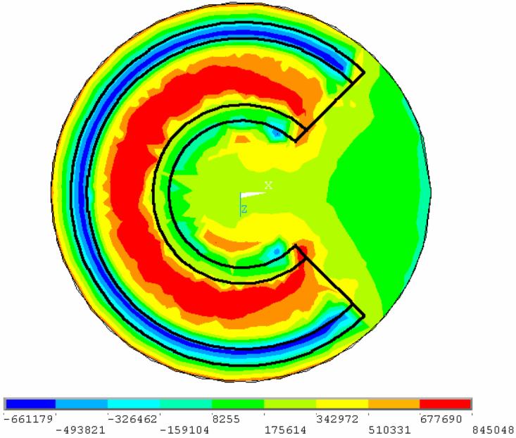
Contour plot of maximum principal stress on a plane cutting through center of the blood vessel, illustrating close to uniform level of maximum stress in the CPA contained in the blood vessel. Maximum tensile stress in CPA acts in axial direction along the blood vessel.
The maximum tensile stress in the CPA of the 3D model is 43% of the maximum CPA tensile stress in the baseline concentric cylinder model, Fig. 1(b); both maximum stresses act along the vessel axis. This comparison of stress is consistent with the following analysis. The upper and lower bases of the CPA domain in the 3D model are 0.5 mm away from the blood vessel, while the cylindrical surface of the CPA domain is 2 mm away from the blood vessel (and additional CPA is present at the inner part of the domain). Thus, one may consider comparing the stresses in the 3D case with a concentric cylinder model featuring surrounding CPA in a thickness range of 0.5 mm to 2 mm, as illustrated in Fig. 1(d). The latter two extreme cases yield stress ratios of 74% and 36%, respectively, relative to the baseline case, Fig. 1(b); these values bound the stress value of 43% in the 3D case. The precise stresses in the 3D model would obviously vary in an even more complex way if the blood vessel would not be perfectly circular and symmetrically oriented and positioned in the domain. Nevertheless, this comparison demonstrates that the general level of stresses in the CPA for a 3D geometry can be approximately predicted, or bounded, from a simplified concentric cylindrical model, at least once the CPA responds elastically below the set-temperature. This observation can be efficiently used in future analysis, in efforts to optimize cryopreservation applications.
Summary and Conclusions
The current study focuses on analysis of thermal stress development in blood vessels, in processes associated with vitrification. More specifically, the current study has the goal of shedding light on the case of a partially vitrified specimen in a completely vitrifying medium. As an initial attempt to investigate this problem, an extreme case is analyzed, in which the specimen completely crystallizes, while the medium completely vitrifies. This scenario is expected to produce an upper bound to stresses in a partially vitrified sample. It is the anticipation of the authors of this paper that the current analysis will assist in experimental design in future studies.
Two basic cases of stress development are presented in this study: a straight long blood vessel, analyzed as a 2D axi-symmetric problem, and a curved blood vessel placed in a storage vial, analyzed as a full 3D problem. The 2D case is further studied with respect to variations in the volume of CPA contained in the blood vessel, surrounding the blood vessel, and variations in the elastic moduli of the blood vessel and CPA.
Results of this study are consistent with a previous observation that, in a vitrifying material, a set-temperature exists, below which the material behaves linear elastically at any practical time scale. Once established, this observation has a dramatic effect of reducing computation efforts, while generating credible results of stress development at low temperatures. This study demonstrates how computation can be further reduced, where results from a set of simpler 2D problems can be applied to bound the results of the more realistic 3D problem.
Results of this study indicate that the stress in the CPA is primarily tensile, while stress in the blood vessel is primarily compressive. It is the tensile stress that is known to be associated with fracture formation in brittle materials. In particular, the maximum tensile stress in the CPA acts in the axial direction and is uniform over the cross-section. Such stresses are consistent with cracks traversing the CPA up to the interface with the blood vessel. Such fractures could propagate into the blood vessel wall, at least on the small scale of a few μm. If such mechanical damage occurs at the lumen, or to endothelial cells, it can cause the blood vessel to completely lose its functionality at the end of the cryopreservation protocol. Contrary to common belief, it is found from this study that the stress in the CPA decreases with increasing CPA volume, as long as the assumption of uniform temperature distribution is valid. With lower stresses, there is greater likelihood of bringing the tissue to storage temperatures without fracture occurring in the CPA and threatening the blood vessel.
Acknowledgment
This study has been supported by National Heart Lung and Blood Institute - NIH, grant number R01 HL069944-01A1, R01 HL069944-02, R01 HL069944-03.
References
- 1.Report of a working party of the British Cardiac Society: Coronary Angioplasty in the United Kingdom. Br Heart J. 1991;66:325–331. doi: 10.1136/hrt.66.4.325. [DOI] [PMC free article] [PubMed] [Google Scholar]
- 2.Heart and Stroke Facts: Statistical Supplement. American Heart Association; 1996. [Google Scholar]
- 3.Callow AD. Historical overview of experimental and clinical development of vascular grafts. In: Stanley J, editor. Biologic and synthetic vascular prosthesis. Grune and Stratton; New York: 1983. [Google Scholar]
- 4.World Cell Therapy Markets (ISBN 0-7889-0693-3).Frost & Sullivan. 1997:5413–43. Revision #1. [Google Scholar]
- 5.Edwards WS, Holdefer WF, Motashemi M. The importance of proper caliber of lumen in femoral popliteal artery reconstruction. Surg Gynecol Obstet. 1966;122(1):37–40. [PubMed] [Google Scholar]
- 6.Hunt CJ, Song YC, Bateson EAJ, Pegg DE. Fractures in cryopreserved arteries. Cryobiology. 1994;31:506–515. doi: 10.1006/cryo.1994.1061. [DOI] [PubMed] [Google Scholar]
- 7.Pegg DE, Wustman MC, Boylan S. Fractures in cryopreserved elastic arteries. Cryobiology. 1997;34:183–192. doi: 10.1006/cryo.1996.1997. [DOI] [PubMed] [Google Scholar]
- 8.Nataf P, Hadjiisky P, Lechat P, Mougenot N, Peuchmaurd M, Gouezo R, Gerota J, Cabrol C, Gandjbakhch I. Effect of cold anoxia and cryopreservation on metabolic and contractile functions of human mammary artery. Cryobiology. 1995;23:327–333. doi: 10.1006/cryo.1995.1033. [DOI] [PubMed] [Google Scholar]
- 9.Almassi GH, Farahbakhsh B, Wooldridge T, Rusch NJ, Olinger GN. Endothelium and vascular smooth muscle function in internal mammary artery after cryopreservation. J Surg Res. 1996;60:355–360. doi: 10.1006/jsre.1996.0057. [DOI] [PubMed] [Google Scholar]
- 10.Muller-Schweinitzer E, Stulz P, Striffeler H, Haefeli W. Functional activity and transmembrane signaling mechanisms after cryopreservation of human internal mammary arteries. J Vasc Surg. 1998;27:528–537. doi: 10.1016/s0741-5214(98)70328-3. [DOI] [PubMed] [Google Scholar]
- 11.Stanke F, Riebel D, Carmine S, Cracowski J-L, Caron F, Magne J-L, Egelhoffer H. Functional assessment of human femoral arteries after cryopreservation. J Vasc Surg. 1998;28:273–283. doi: 10.1016/s0741-5214(98)70163-6. [DOI] [PubMed] [Google Scholar]
- 12.Taylor MJ, Song YC, Brockbank KGM. Vitrification in tissue preservation: new developments. In: Fuller BJ, Lane N, Benson EE, editors. Life in the Frozen State. CRC Press; New York: 2004. pp. 603–641. [Google Scholar]
- 13.Song YC, Khirabadi BS, Lightfoot FG, Brockbank KGM, Taylor MJ. Vitreous cryopreservation maintains the function of vascular grafts. Nature Biotechnology. 2000;18:296–299. doi: 10.1038/73737. [DOI] [PubMed] [Google Scholar]
- 14.Karow AM. Biophysical and chemical considerations in cryopreservation. In: Karow AM, Pegg DE, editors. Organ preservation for transplantation. Dekker; New York: 1981. p. 113. [Google Scholar]
- 15.Mazur P. Freezing of living cells: mechanisms and implications. Am J Physiol. 1984;247(3 Pt 1):C125–42. doi: 10.1152/ajpcell.1984.247.3.C125. [DOI] [PubMed] [Google Scholar]
- 16.Pegg DE. Ice crystals in tissues and organs. In: Pegg DE, Karow AM Jr., editors. The biophysics of organ preservation. Plenum Publishing Corp.; New York: 1987. pp. 117–140. [Google Scholar]
- 17.Taylor MJ. Sub zero preservation and the prospect of long term storage of multicellular tissues and organs. In: Calne RY, editor. Transplantation immunology: clinical and experimental. Oxford University Press; Oxford New York Tokyo: 1984. pp. 360–390. [Google Scholar]
- 18.Rabin Y, Taylor MJ, Walsh JR, Baicu S, Steif PS. Cryomacroscopy of vitrification, Part I: A prototype and experimental observations on the cocktails VS55 and DP6. Cell Preservation Technology. 2005;3(3):169–183. doi: 10.1089/cpt.2005.3.169. [DOI] [PMC free article] [PubMed] [Google Scholar]
- 19.Steif PS, Palastro M, Wen CR, Baicu S, Taylor MJ, Rabin Y. Cryomacroscopy of vitrification, Part II: Experimental observations and analysis of fracture formation in vitrified VS55 and DP6. Cell Preservation Technology. 2005;3(3):184–200. doi: 10.1089/cpt.2005.3.184. [DOI] [PMC free article] [PubMed] [Google Scholar]
- 20.Rabin Y, Steif PS, Hess KC, Jimenez-Rios JL, Palastro MC. Fracture formation in vitrified thin films of cryoprotectants. Cryobiology. 2006;53:75–95. doi: 10.1016/j.cryobiol.2006.03.013. In conjunction with http://www.me.cmu.edu/faculty1/rabin/CryomacroscopyImages02.html. [DOI] [PMC free article] [PubMed] [Google Scholar]
- 21.Plitz J, Rabin Y, Walsh JR. The effect of thermal expansion of ingredients on the cocktails VS55 and DP6. Cell Preservation Technology. 2004;2(3):215–226. [Google Scholar]
- 22.Rabin Y, Taylor MJ, Wolmark N. Thermal expansion measurements of frozen biological tissues at cryogenic temperatures. ASME J. of Biomech. Eng. 1998;120(2):259–266. doi: 10.1115/1.2798310. [DOI] [PubMed] [Google Scholar]
- 23.Rabin Y, Plitz J. Thermal expansion of blood vessels and muscle specimens permeated with DMSO, DP6, and VS55 in cryogenic temperatures. Annals of Biomedical Engineering. 2005;33(9):1213–1228. doi: 10.1007/s10439-005-5364-0. [DOI] [PubMed] [Google Scholar]
- 24.Pegg DE. Principles of tissue preservation. In: Morris PJ, Tilney NL, editors. Progress in transplantation. Churchill Livingston; Edinburgh: 1985. pp. 69–105. [Google Scholar]
- 25.Schichman SA, Amey RL. Viscosity and local liquid structure in dimethyl sulfoxide - water mixtures. J. of Phys. Chem. 1971;75(1):98–102. [Google Scholar]
- 26.Malvern LE. Introduction to the mechanics of a continuous medium. Prentice-Hall; Englewood Cliffs, New Jersey: 1969. [Google Scholar]
- 27.Richerson DW. Modern ceramic engineering: properties, processing, and use in design. Marcel Dekker, Inc.; New York: 1992. [Google Scholar]
- 28.Ashby MF, Jones DRH. Engineering materials: an introduction to their properties and applications. Pergamon Press; Oxford: 1980. [Google Scholar]