

Abstract
At a late stage in Drosophila oogenesis, nurse cells rapidly expel their cytoplasm into the oocyte via intracellular bridges by a process called nurse cell dumping. Before dumping, numerous cables composed of actin filaments appear in the cytoplasm and extend inward from the plasma membrane toward the nucleus. This actin cage prevents the nucleus, which becomes highly lobed, from physically blocking the intracellular bridges during dumping. Each cable is composed of a linear series of modules composed of ∼25 cross-linked actin filaments. Adjacent modules overlap in the cable like the units of an extension ladder. During cable formation, individual modules are nucleated from the cell surface as microvilli, released, and then cross-linked to an adjacent forming module. The filaments in all the modules in a cable are unidirectionally polarized. During dumping as the volume of the cytoplasm decreases, the nucleus to plasma membrane distance decreases, compressing the actin cables that shorten as adjacent modules slide passively past one another just as the elements of an extension ladder slide past one another for storage. In Drosophila, the modular construction of actin cytoskeletons seems to be a generalized strategy. The behavior of modular actin cytoskeletons has implications for other actin-based cytoskeletal systems, e.g., those involved in Listeria movement, in cell spreading, and in retrograde flow in growth cones and fibroblasts.
Two questions have puzzled us for some time. First, what controls the length of actin filaments and/or bundles of actin filaments and, second, what controls the number of actin filaments in a bundle and thus the diameter of the bundle. We recognize that in certain cells the length of actin filaments is rigorously controlled, e.g., in erythrocytes, in skeletal muscle cells (see Fowler, 1996), and in the stereocilia of the ear (Tilney et al., 1992a ). In erythrocytes and in skeletal muscle, it seems likely that both barbed and pointed-end cappers and a measuring element like tropomyosin or nebulin are used, but in other cases where the filaments are longer, e.g., stereocilia, intestinal microvilli, or Drosophila bristles, how lengths are controlled remains mysterious. Likewise, what decides how many filaments are to be included in a single bundle is also unclear. For example, why does each intestinal microvillus only contain 20–30 filaments, yet a stereocilium contains 250–500?
We and others have begun to address these issues by studying Drosophila mutants in which specific actin-associated proteins are either reduced or increased in concentration. Two cell types have been examined because distinct phenotypes can be easily recognized: ovarian nurse cells and thoracic bristles. In earlier papers we described in some detail the organization of actin filaments in bristles (Tilney et al., 1995, 1996b ) and in ring canals (Tilney et al., 1996a ). There is an additional bundle type in the ovarian nurse cells that has not yet been analyzed in detail even though alterations in actin binding proteins such as fascin (Cant et al., 1994; Cant and Cooley, 1996), villin (Mahajan-Mikios and Cooley, 1994), and profilin (Cooley et al., 1992) dramatically affect this bundle type. It is our hope that a detailed description of this third system will be useful because it combines elements of the first two systems but results in a quite different cytoskeletal organization. By comparing these three systems, each of which has an independent assortment of actin binding proteins, we have an additional handle in understanding what controls filament length and number.
Each ovarian follicle consists of 15 polyploid nurse cells connected to one another and to a single oocyte by cytoplasmic bridges or ring canals. Throughout oogenesis, which takes 2–3 d, nurse cell cytoplasm containing maternal RNA, organelles, and proteins flows slowly into the oocyte through these bridges. Late in oogenesis, stage 11, the nurse cell cytoplasm is rapidly expelled into the oocyte, a process called nurse cell dumping (Fig. 1). This results in a doubling of the oocyte volume in 30 min. All that is left in the nurse cells are nuclei, some actin bundles, and presumably minimal cytoplasm (for review see Spradling, 1993).
Figure 1.

Diagram of nurse cell dumping during the late stages of Drosophila oogenesis. During stage 10B (4 h), the collective nurse cell cytoplasm (dark stippling) accounts for half the volume of the egg chamber, whereas the oocyte accounts for the other half (light stippling). The polytene nurse cell nuclei are shown as circles whereas the nurse cell plasma membranes are omitted for clarity. During stage 11 (30 min), the nurse cells contract and dump their cytoplasmic contents into the oocyte. As a result, nurse cell volume is reduced relative to oocyte volume. Stage 12 egg chambers (2 h) are characterized by a relatively small nurse cell component still containing nuclei.
Gutzeit (1986) showed that the force for the final dumping is sensitive to cytochalasin and thus is actin filament dependent. There are three sets of actin filaments in the nurse cell during dumping: a subcortical layer associated with the surface of the nurse cells, the actin filaments lining the ring canals, and a network of cytoplasmic actin bundles that extend from the cortex toward the nucleus. Since the actin filaments lining the ring canals and the cytoplasmic bundles are insensitive to cytochalasin, Gutzeit (1986), and more recently Cooley et al. (1992), concluded that the cortical layer was responsible for dumping. Consistent with this idea is the observation that, in mutants where the cytoplasmic bundles do not form, some nurse cell cytoplasm flows into the oocyte during stage 11, but transfer is incomplete because the nuclei, by not being restrained by the cytoplasmic bundles, physically block the canals (Cooley et al., 1992; Cant et al., 1994; Mahajan-Mikios and Cooley, 1994). Evidence that the subcortical layer contracts by an actomyosin process is indicated by mutants that produce mutant myosin II regulatory light chain (Wheatley et al., 1995). In these mutants dumping does not occur even though the three actin systems are intact.
Recently, Riparbelli and Callaini (1995) published some magnificent confocal images of actin bundles in nurse cells showing that they are striated. If these bundles are contractile like the stress fibers, this may help to explain dumping. However, unlike the actin bundles in nurse cells, the actin in stress fibers usually appears continuous by light microscopy, whereas the actin binding proteins such as myosin, α-actinin, and tropomyosin appear periodic (Gordon, 1978; Sanger et al., 1986).
What we have discovered here is that each nurse cell actin bundle, which we will refer to as a cable, is composed of a series of smaller units or modules each containing ∼25 filaments. These modules are laterally associated with each other and overlap like the elements of an extension ladder. From the diameter of each module and the fact that the cables extend from microvilli located just peripheral to the ring canals, we conclude that each module assembles attached to the membrane and is subsequently released from the membrane where it becomes laterally associated with another module that is in the process of being assembled. This conclusion is strengthened by the observation that all of the filaments in a cable have the same polarity, and by serial sections of individual cables extending from a microvillus. Such a design fits beautifully with the purpose of the cables: to keep the nucleus, which becomes lobed immediately before dumping, away from the ring canals during dumping. As dumping proceeds, with progressive loss in nurse cell volume, the cables must shorten. They do so by sliding modules past one another like the elements of an extension ladder when the ladder is collapsed before storage. Thus, the cables become thicker during compression so that at the conclusion of dumping the modules maximally overlap, leading to the disappearance of the striations.
Materials and Methods
Drosophila Stocks
The Oregon-R strain of Drosophila melanogaster was used as the wild type in these studies. The singedX2 stock [In(1)dl-49, snX2] and the kelch stock (kelneo) were obtained from the Drosophila Stock Center (Indiana University, Bloomington, IN) and from Lynn Cooley (Yale University, New Haven, CT), respectively. The snX2 allele was maintained over the In(1) Mud, Mud1 chromosome. snX2/snX2 adult females were identified by their wild-type (Mud+) eye phenotype and singed bristle phenotype. The kelneo allele was maintained over the CyO balancer (Lindsley and Zimm, 1992). kelneo/kelneo adult females were identified by their wild-type (Cy+) wing phenotype. Flies were maintained on standard cornmeal/molasses/ yeast food at 25°C, 60–70% relative humidity, with a 12 h/12 h day/night cycle. Complete descriptions of genes and symbols can be found in Lindsley and Zimm (1992) and on FlyBase (Gelbart et al., 1997). To obtain ovarioles with follicles at stages 10–12 of oogenesis, we took newly emerged flies and placed them in new vials for 4 d. One day before the flies were killed, we added a dollop of yeast paste to stimulate oogenesis. Upon dissection few mature eggs were encountered, but there were many at stages just before maturity.
Obtaining Eggs
Flies were anesthetized with CO2 and their abdomens were removed and immersed in the Drosophila glutamate saline described by Singleton and Woodruff (1994). The formulation and reason for using this glutamate saline are covered in Tilney et al. (1996a). The ovarioles were separated with needles and late stage follicles were dissected from the ovarioles. Individual follicles were collected and processed for either light microscopy or EM. Staging of the follicles was carried out using the description and photographs of Spradling (1993).
Fixation and Processing for Light Microscopy
The isolated follicles were fixed for 20 min in PBS containing 4% paraformaldehyde, and then permeabilized for 20 min in PBS containing 4% paraformaldehyde plus 0.1% Triton X-100. The follicles were then stained in PBS containing 4% paraformaldehyde, 0.1% Triton X-100, and 1 μM phalloidin conjugated to rhodamine (Sigma Chemical Co., St. Louis, MO). The follicles were then washed in PBS, placed on a slide, and immersed in PBS-Citifluor (Ted Pella, Redding, CA). A coverslip was added and the preparation was sealed with nail polish. The slide was then examined with a Zeiss Universal fluorescent microscope (Carl Zeiss, Inc., Thornwood, NY) or a Leitz model TCS 4D confocal microscope (Leica, Heidelberg, Germany). Confocal images were examined and printed using Adobe Photoshop (Adobe Systems Inc., Mountain View, CA).
Fixation for EM
For routine examination, follicles were fixed by immersion in a freshly made solution of 1% glutaraldehyde (from an 8% stock; Electron Microscope Sciences, Fort Washington, PA), 1% OsO4, and 0.05 M phosphate buffer at pH 6.2. Fixation is carried out for 45 min at 4°C. Since the glutamate in the Drosophila saline (small quantities were introduced when the follicles were pipetted into fixative) interacts with the fixative, after 5 min the follicles were put into fresh fixative.
Decoration with Subfragment 1 of Myosin
After dissection in the glutamate saline solution just described, follicles were extracted for 10 min at 4°C in a solution containing 1% Triton X-100, 3 mM MgCl2, and 30 mM Tris (pH 7.5) with gentle agitation in a rotating shaker. After detergent extraction, the follicles were incubated in a solution containing 4 mg/ml subfragment 1 of myosin (S1)1 in 0.1 M phosphate buffer (pH 6.8) for 20 min at room temperature with gentle agitation. The S1 had been prepared many years before and kept frozen in small aliquots in liquid nitrogen at a concentration of 70 μg/ml (Tilney and Tilney, 1994).
After decoration, specimens were washed in phosphate buffer and fixed at room temperature in 1% glutaraldehyde in 0.1 M phosphate buffer at pH 6.8 containing 2% tannic acid. The preparations were then washed in buffer, postfixed for 45 min at 4°C in 1% OsO4 in 0.05 M phosphate buffer at pH 6.2, and processed further as mentioned below.
Embedding, Thin-sectioning, and EM
After fixation, the follicles were washed three times for 5 min each in 4°C water to remove excess phosphate and stained en bloc overnight in 0.5% uranyl acetate. The specimens were then dehydrated in acetone and embedded in Epon. Thin-sections were cut with a diamond knife, stained with uranyl acetate and lead citrate, and examined with the electron microscope (Philips 200; Philips Electronic Instruments, Inc., Mahwah, NJ). Sets of serial sections were collected on Formvar-coated single-slot grids. For routine observations, uncoated grids were used.
Measurements of Nuclear Surface Areas and Volume
Low magnification micrographs of nuclei were taken and enlarged photographically 2.6 times. The micrographs were covered with mylar and the outline of the nucleus was traced. The circumference (C) was determined with a planimeter. We used the measured circumference to estimate the radius of the nucleus (r = C/2π). We then used this radius value to estimate the surface area of the nucleus (SA = 4πr2). The volumes of the same nuclei were calculated by first measuring the nuclear area in the EM section by cutting out its profile on the mylar with scissors and weighing the resultant cutout. From that weight (W) we estimated a radius of that piece (r =  ) and used this value to calculate the volume of the whole nucleus (V = 4/3πr3). The values are shown in Table II.
Table II.
Nurse Cell Nuclei: Surface Area and Volume
| Stage | Surface area ± SEM | Volume ± SEM | Number of nuclei | |||||||
|---|---|---|---|---|---|---|---|---|---|---|
| μm2 | μm3 | n | ||||||||
| 5 | 209 | ± 215 | 1,518 | ± 470 | 2 | |||||
| 9 | 1,504 | 1,449 | 1 | |||||||
| 10A | 1,492 | 3,157 | 1 | |||||||
| 10 B | 4,507 | ± 666 | 10,098 | ± 1,462 | 7 | |||||
| 11 | 13,683 | ± 3,703 | 7,327 | ± 1,668 | 3 | |||||
| 12 | 11,403 | ± 2,378 | 5,940 | ± 698 | 3 | |||||
| snX2 | 11,166 | ± 3,190 | 5,886 | ± 0 | 2 | |||||
The surface area and volume of nurse cell nuclei from different stages in oogenesis were estimated from electron micrographs as described in Materials and Methods. The values given are ± SEM. The number of nuclei analyzed for each group (n) is also given.
Results
Light Microscopy of Actin Bundles in Nurse Cells
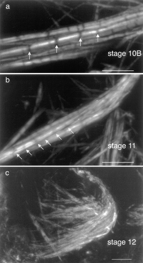
As shown initially by Gutzeit (1986) and Warn et al. (1985), actin bundles in late stage 10 follicles appear to extend inward from the surface of the nurse cell radially to the nucleus, thereby forming a cage around the nucleus. Light microscopic examination of phalloidin-stained nurse cells shows the central part of the cell containing the large polyploid nucleus to be completely dark (Fig. 2 a). At higher resolution each actin bundle appears striated, reminiscent of the sarcomeres of skeletal muscle (Fig. 2 b). There are distinct differences from skeletal muscle, however. First, the brightly fluorescent portions of the bundles vary in length. Second, the intensities of the bright fluorescent regions vary considerably; some are very bright, whereas others, often in the same bundle, are less fluorescent. Third, the portion of the bundle between fluorescent segments is not black but contains some fluorescent material (Fig. 2 b), albeit at lower levels of intensity of fluorescence than the bright regions. And fourth, the diameters of the bundles appear to vary. By fluorescent microscopy one cannot determine actual diameters, but it is clear that some bundles are thin while others are much thicker.
Figure 2.
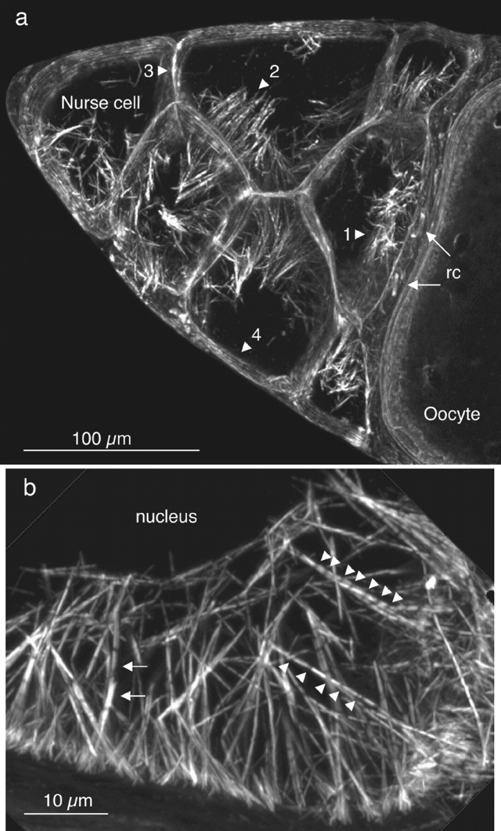
Portions of wild-type stage 10B egg chambers stained with rhodamine-conjugated phalloidin and examined by confocal microscopy. (a) Cortical actin staining outlines 7 of the 15 nurse cells (left) and the anterior portion of the oocyte (right). Two ring canals (rc) that connect the oocyte to the nurse cells are also indicated (arrows). The nurse cells contain prominent arrays of actin bundles extending from the plasma membrane toward the nucleus (dark regions within the nurse cells). These cables are located on plasma membranes adjacent to the oocyte (1), adjacent to other nurse cells with a common ring canal (2), adjacent to other nurse cells without a ring canal connection (3), and adjacent to follicle cells surrounding the egg chamber (4). The densities of these cables along the nurse cell plasma membrane are indicated in Table I. This is a 14-μm optical section. (b) The actin cables originate from the plasma membrane and extend toward and outline the nucleus (dark region). The striated actin cables exhibit gaps at low (leftward arrows), medium (upward arrowheads), and high (downward arrowheads) frequencies. In addition, the F-actin staining intensity in the gaps between the striations is often well above background. Also, the fluorescent intensity of adjacent modules in the same cable can be quite different (leftward arrows) and probably reflects the presence of overlapping actin bundles. The oocyte (not shown) of this egg chamber is connected to this nurse cell. This is a 6-μm optical section. Bars: (a) = 100 μm; (b) 10 μm.
Adjacent bundles that extend from the nurse cell surface often merge together into a common bundle like the branches of a tall tree. The striations in the subbundles at or near the point of merger are in register so that the merged common bundle has striations that extend all the way across the now thick, merged bundle.
Although the radially oriented actin bundles appear to cage the nucleus, like the spikes from the surface of the “iron maiden” medieval torture device, the bundles are not distributed equally along all surfaces of the nurse cells (Table I). Thus, fewer bundles extend from the nurse cell margins adjacent to the follicular epithelium or a nurse cell margin that lacks ring canals (Fig. 2 a, regions 3 and 4). Instead the bulk of the bundles extend from regions of the nurse cell in close proximity to the ring canals (Fig. 2 a, regions 1 and 2).
Table I.
Actin Cables in Drosophila Nurse Cells
| Class | Adjoining cells | Length of plasma membrane | Number of cell–cell pairs | Actin bundles per μm | ||||
|---|---|---|---|---|---|---|---|---|
| μm | n | |||||||
| 1 | Nurse/oocyte | 370 | 4 | 0.41 ± 0.07 | ||||
| 2 | Nurse/nurse | 844 | 18 | 0.62 ± 0.08 | ||||
| 3 | Nurse/nurse (no RC) | 100 | 3 | 0.03 ± 0.02 | ||||
| 4 | Nurse/follicle | 267 | 4 | 0.02 ± 0.01 |
Nurse cell actin cables seen in confocal optical sections (5 μm) from four phalloidin-stained, wild-type stage 10B egg chambers were counted. The nurse cell plasma membranes were adjacent to the oocyte (class 1), to other nurse cells (class 2 and 3), or to surrounding follicle cells (class 4). Several adjacent nurse cells (class 3) were not connected by ring canals (RC). An example of each class is highlighted in Fig. 2 a. The length of the plasma membrane examined (μm) and the number of cell–cell pairs (n) are given for each class. The average number of actin cables per μm of membrane is given ± SEM. Actin cables are much more abundant along nurse cell plasma membranes containing ring canals (class 1 and 2).
As described by Cant et al. (1994), singedX2 (snX2) females produce sterile eggs. Western and immunofluorescence analyses showed that the singed protein is absent from the nurse cells (Cant et al., 1994). Since the molecular defect of this mutation is unknown (Paterson and O'Hare, 1991), tiny amounts of the protein, beneath the limit of detection by these techniques, could be present in these cells. The phenotype described by Cant et al. (1994) was a severe reduction in cytoplasmic actin bundles, but the ring canals and subcortical actin appeared to be like the wild type. When we examine the cytoplasmic surface of snX2 nurse cell plasma membrane by phalloidin staining, we find normal-appearing subcortical actin attached to the plasma membrane (Fig. 3 a). Tiny actin bundles, seldom >7 μm in length, can also be found extending from the nurse cell plasma membrane into the cytoplasm (Fig. 3, a and b) as in the wild type. These bundles are generally found near ring canals. Although these bundles are short, they are nevertheless striated (Fig. 3 b) as in the wild type. Ring canal morphology in snX2 nurse cells ranges from nearly wild type (e.g., Fig. 3 a) to very disorganized (unpublished observations).
Figure 3.

Portions of singedX2 stage 10 egg chambers stained with rhodamine-conjugated phalloidin and examined by confocal microscopy. (a) The cortical actin and two ring canals between three nurse cells are shown. There is a wide variety of ring canal morphologies in snX2 egg chambers (unpublished observations). The ring canals shown here look nearly wild type in appearance. (b) The cortical actin and striated actin cables between two nurse cells are shown. For comparison, a wild-type nurse cell at approximately the same stage is shown in Fig. 2 b. These are 6- (a) and 7-μm (b) optical sections. Bars: (a) 10 μm; (b) 5 μm.
Changes in Nuclear Morphology, Volume, and Surface Area Immediately before Dumping
What had not been observed earlier, because one needs the greater resolution of the electron microscope, is that the nurse cell nuclei change dramatically in the stages immediately before dumping. These changes provide an explanation of why the actin cables are so numerous and are distributed nonuniformly. Furthermore, these nuclear changes explain how the ring canals are plugged in cable-affected mutants such as singed.
In thin-sections through a stage 10A follicle before the formation of the radially oriented actin bundles, we find that the nucleus is nearly spherical. It contains enormous numbers of nuclear pores so tightly packed that there is insufficient room for additional ones. At an early stage 10B, before the appearance of long actin bundles, the surface of the nucleus is a bit more irregular in shape but basically spherical (Fig. 4 A). However, by stage 11 when the actin bundles are fully formed, the nucleus is extensively infolded and now contains numerous lobes (Fig. 4 B). A more precise way of describing this is to compare the surface area of stage 10B and 11 nuclei. Interestingly, the surface area increases by threefold but the volume stays the same or decreases slightly (Table II). The density of nuclear pores does not change (data not shown), so they increase in total number as the surface enlarges. From these images of lobed nuclei, we can now appreciate why, biologically, the nurse cells need to have so many actin bundles to restrain the nucleus during dumping. If only a few bundles were to be present, individual lobes could block the ring canals and thus inhibit cytoplasmic flow into the oocyte. Besides obvious changes in the topography of the nucleus, the chromatin in the nucleus changes dramatically when one compares a stage 10B and stage 11 nucleus. At stage 10B we find a few large, dense, heterochromatic masses that resemble nucleoli (Fig. 4 A). By stage 11 both large and small heterochromatic regions are present throughout the nucleus (compare Figs. 4 A and 4 B).
Figure 4.
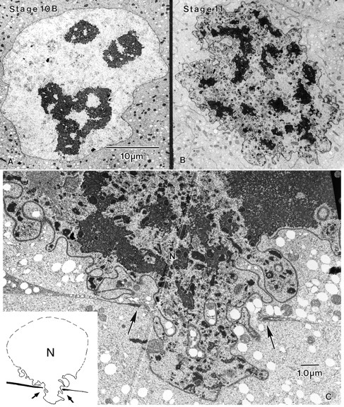
Thin-sections through wild-type and mutant nurse cell nuclei. (A) At stage 10B a wild-type nucleus is nearly round and contains large dense masses that superficially resemble nucleoli. (B) In contrast, at stage 11 the wild-type nuclear surface is indented and lobed. The nucleoplasm is much denser with numerous areas of heterochromatin. Printed at the same magnification as a. (C) Thin section through a portion of two nurse cells from the singedX2 mutant at stage 11. In this section a large lobe from the nucleus (N) has entered the ring canal, whose margins are indicated by the arrows. This nuclear lobe has effectively plugged the canal. In the inset we have diagrammed what this looks like at lower magnification as in the micrograph. The margins of the ring canals are indicated by the arrows. Bars: (A) 10 μm; (C) 1 μm.
The Change in Nuclear Morphology Is Not Caused by the Cytoplasmic Actin Cables
We asked whether the nurse cell actin cables caused the changes in nuclear morphology. We could determine this by examining singed nurse cells. Since the criterion for identifying stage 11 and 12 egg chambers in wild-type flies is based on the relative sizes of the oocyte and the nurse cell cluster, it is difficult to stage singed mutant follicles after stage 10B because nurse cell dumping does not occur in this mutant. Since these latter stages cannot easily be distinguished from one another or from late stage 10B, we examined large follicles that contain all these stages (10B– 12). Thin-sections of these large follicles revealed that the nurse cell nuclei are lobed and closely resemble wild-type stage 12 nurse cell nuclei. Quantitatively, the singed and wild-type stage nuclei are identical both in total surface area and in volume (Table II). Since there are no actin bundles near the singed nuclei and/or between the lobes of the nucleus, the extensive lobation of late stage nuclei cannot be related to the actin cytoskeleton.
Cant et al. (1994) showed by light microscopy that singed mutants block dumping by the nucleus plugging the ring canals. In thin-sections we can confirm this observation and extend it. What occurs is that an individual lobe of the nucleus is pushed into a ring canal presumably by contraction of the subcortical actin (see Introduction) and totally occludes the canal (Fig. 4 C). This explains why in the light micrographs of Cant et al. (1994) the stuck nuclei appear morphologically like wine bottles with their necks stuck in the ring canals.
The Relationship of the Actin Bundles to the Nuclear Envelope and the Nurse Cell Plasma Membrane
By light microscopy, the actin bundles appear to terminate on the surface of the nucleus as if they were attached. However, in thin-sections examined by EM, it is apparent that the bundles are not attached directly to the nuclear envelope but terminate at a short distance from the envelope (data not shown). Often individual bundles appear between lobes of the nucleus, lying perpendicular to the radially oriented cables. From these observations and those on singed nuclei where cables do not extend very far from the nurse cell plasma membrane, we conclude that the actin bundles form a three-dimensional cage that restrains the nucleus but does not interact with it directly.
In stage 10A we find microvilli on the surface of the nurse cells. These microvilli indent the plasma membrane of adjacent cells, albeit another nurse cell. Filaments, presumably actin filaments, are present in these microvilli. The microvilli are very short, <1 μm in length. The filaments in the microvilli extend a short distance into the nurse cell cytoplasm as a rootlet. Microvilli are not present on the nurse cell surface adjacent to the overlying follicle cells. They are most abundant near ring canals and less abundant the further one goes away from the ring canals.
Favorable sections of stage 10B and 11 follicles reveal short microvilli as before, but extending basally is an extremely long rootlet that leads toward a lobed nucleus (Fig. 5 A). Thus, at least some (and probably all) of the bundles that extend from the nurse cell plasma membrane near ring canals are basal extensions of microvilli.
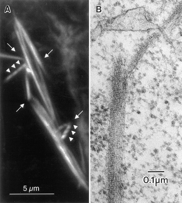
Figure 5.
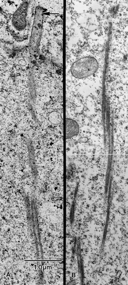
Thin-sections through a portion of the surface of a wild-type nurse cell. (A) Extending basally from a microvillus (arrow) is an actin filament bundle. This bundle, as it extends basally, is connected to other actin bundles that run parallel to it. (B) Thin-section cut deeper in the cytoplasm. This micrograph illustrates that actin bundles associate laterally with other bundles. Although it cannot be proven from these two micrographs, individual bundles appear short (e.g., 2–3 μm) but overlap like the units of an extension ladder. Both A and B are cut from stage 11 follicles and printed at the same magnification. Bar, 1 μm.
The Filament Cables Visualized by Light Microscopy Are Composed of a Series of Laterally Associated Modules
In thin-sections cut longitudinally through a cable, we often see that the cable is not homogeneous but consists of subbundles or modules aligned parallel to each other (Fig. 5, A and B). To try and see the extent of these subbundles, we cut serial sections through the nurse cell cytoplasm. One of these sequences is shown in Fig. 6. What is interesting in this series and in others not shown is that individual modules end so that in a following section no evidence of the bundle is found (Fig. 6, bundle 1). Other modules appear (Fig. 6, bundles 2 and 3) and associate laterally with a rootlet bundle that extends from a microvillus. This means that the cables are actually composed of modules that do not run the full distance from microvilli on the nurse cell surface to the nucleus. Unfortunately, from these serial sections we could not determine the average length of the modules. In the few sections in which we found what appeared to be both ends of a module, we estimate that the modules are 2–4 μm long.
Figure 6.
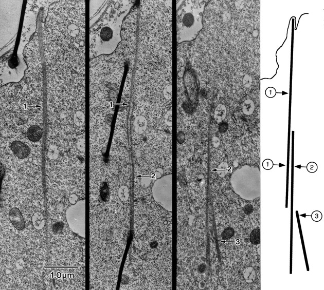
Serial thin-sections through a portion of the cytoplasm of a wild-type stage 11 nurse cell. Of interest here is that short actin bundles associate laterally to form a single continuous cable. One end of the cable extends basally from a microvillus and associates with a second bundle that, in turn, associates with a third. From these serial sections and one not included, we know that bundle 2 begins and ends within the cytoplasm proper and is not attached to the membrane. The drawing on the right illustrates the bundles and how they are associated with each other. Bar, 1 μm.
The Number of Filaments per Module Is Remarkably Constant
By magnifying transverse sections through cables (Fig. 7, B and C), we were able to count the number of filaments in each module. As shown in Fig. 8, the average number is 26. In some cases, the number is approximately double this number (Fig. 7 B) and the bundle is rectangular in shape (Fig. 7 C). We believe that these are instances in which two modules are close together and probably connected.
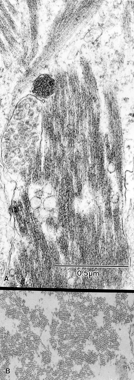
Figure 7.
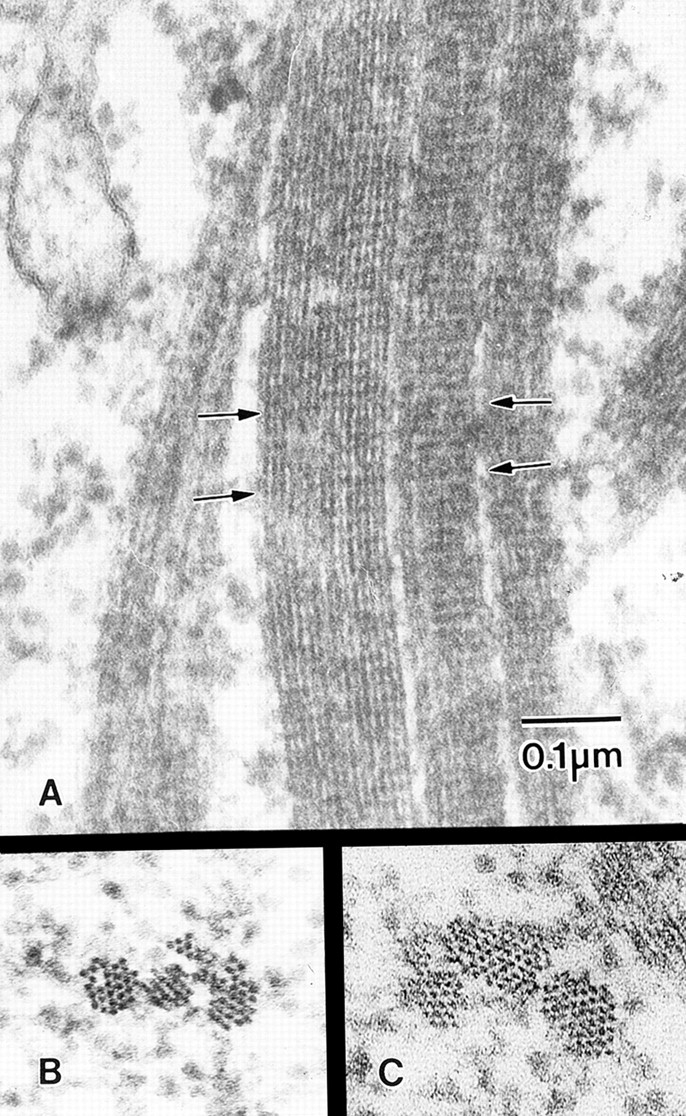
Higher magnification views of thin-sections through cables composed of small bundles. These sections are cut from wild-type stage 11 follicles. All are printed at the same magnification. (A) The horizontal striations present on each bundle are due to the fascin crossbridges as described by Tilney et al. (1995). The striations of adjacent bundles are in transverse register (arrows). (B) Three nearby bundles seen in transverse section. (C) Another cable composed of a small bundle, a medium-sized bundle, and a large bundle. We suspect the large bundle may be composed of two cross-linked small bundles. Bar, 0.1 μm.
Figure 8.
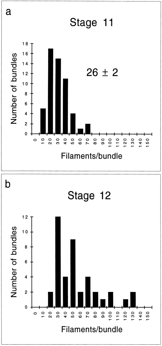
Bar graphs illustrating the number of actin filaments per bundle. Filament number was determined by counting individual filaments in electron micrographs similar to those shown in Figs. 7 (B and C) and 12 B. (a) The number of actin filaments in 55 bundles from wild-type stage 11 egg chambers was counted and their distribution was plotted. The average number of filaments per bundle ± SEM is given. (b) The number of actin filaments in 42 bundles from wild-type stage 12 egg chambers was counted and their distribution was plotted. Peaks at approximately 50, 75, and 100 filaments per bundle reflect the highly overlapping arrangement of these bundles.
The Filaments in Adjacent Modules Have the Same Polarity
As mentioned in the Introduction, the striated cables in nurse cells have a superficial resemblance to stress fibers when examined by light microscopy. Stress fibers have been shown to be like sarcomeres of muscle cells where the actin filaments in either side of the Z line or an α-actinin– containing stripe are of opposite polarity (see Begg et al., 1978; Sanger and Sanger, 1980; Sanger et al., 1986; Langanger et al., 1986). To understand how the cables in nurse cells are constructed and how they change during dumping, it becomes important to determine the polarity of the filaments in the cables as determined by decoration with S1.
When we detergent extract follicles before decoration with S1, the cell membranes of adjacent nurse cells become solubilized. Nevertheless, if we examine the interface between two cells as determined by the position of the nuclei and examine the bundles on one side or the other of this interface, we see regions that contain a number of decorated actin filament bundles closely aligned relative to each other. Careful examination of these adjacent bundles reveals that not only are all of the filaments in each bundle unidirectionally polarized (Fig. 9), but more importantly, the polarity of the filaments in adjacent bundles is also the same. The arrowheads invariably point toward the nucleus. Thus the barbed ends (and presumably growing ends) of the filaments are located close to the nurse cell plasma membrane.
Figure 9.
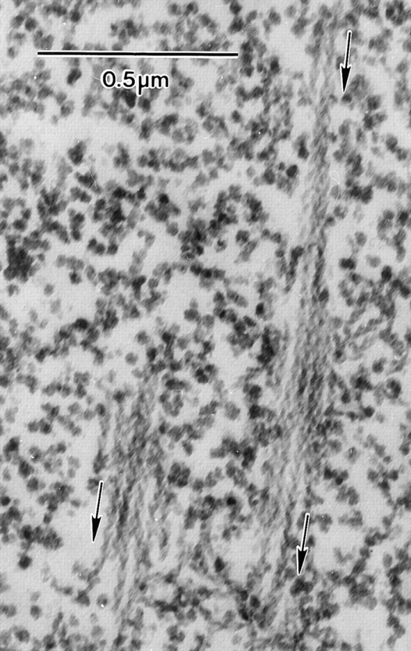
Thin-section through a portion of a nurse cell from a wild-type stage 11 follicle that was detergent extracted and decorated with S1 of myosin before fixation. It is interesting to note that adjacent bundles have an identical polarity as determined by the S1 arrow. In short, the barbed ends are found nearest the plasma membrane. The arrows on the micrographs reflect the polarity of the myosin S1 arrow and point toward the pointed end (plus end) of the actin filaments. Bar, 0.5 μm.
How Is the Striated Appearance of the Cables Viewed by Light Microscopy Related to the Modular View of the Cable Seen in Thin-sections?
Before answering this question there are few observations that should be emphasized. First, the intensity of the fluorescent stripes in an individual cable varies as if there is more material in some stripes and less in others (Fig. 10 a). Second, the thickness of the stripes along a cable can vary. This can be only partly explained by the merging of the separate bundles together (Fig. 10 b). Third, the region between fluorescent stripes is not completely dark like the background, but is generally somewhat fluorescent, indicating that actin filaments must also be present between brightly fluorescent regions (Fig. 10, a and b). Fourth, close examination of the cables reveals that cables can bend sharply as if they are broken. This is particularly common in nurse cells from kelch mutants (Fig. 11). What one sees is that the broken regions are located between the brightly fluorescent bands as if these regions are less stable than the brightly fluorescent regions (Fig. 11 A). In thin-section, it looks like the overlap region between two bundles has cracked apart (Fig. 11 B).
Figure 10.
Portions of wild-type egg chambers stained with rhodamine-conjugated phalloidin and examined by confocal microscopy. Regions containing many overlapping bundles are shown. (a) Stage 10B. Gaps emphasizing the striations (arrows). (b) Stage 11. Gaps emphasizing the striations (arrows) are more frequent per unit length than in earlier stages. In addition, F-actin staining intensity in the gaps is well above background. (c) Stage 12. Here many actin bundles have been compressed and have coalesced to form high density and relatively striation-free bundles. Bars, 5 μm.
Figure 11.
(A) Portion of a kelchneo stage 10 egg chamber stained with rhodamine-conjugated phalloidin and examined by confocal microscopy. A number of striated actin bundles can be seen (arrowheads). Of interest here are the distorted regions characterized by angular intersections of relatively straight bundles (arrows). Similar distortions can be seen in wild-type egg chambers, especially where the actin bundles contact the nuclear envelope (e.g., Fig. 2 b). This is a 3-μm optical section. (B) Thin-section through the portion of the nurse cell cytoplasm from a kelchneo stage 11 egg follicle. Of interest is that the cable appears broken. This occurs at the point of overlap of two modules. Bars: (A) 5 μm; (B) 0.1 μm.
One way to reconcile the fluorescent and thin-section images is to suggest that the portions of the modules that overlap with adjacent modules produce a brightly fluorescent region. As a corollary, the position along a cable where a portion of a module does not overlap with another module is a region of less fluorescence, but not background. A simple analogy may help here. In extension ladders there is a portion of one ladder that overlaps that of the ladder below. This overlap region in essence has two ladder masses (brighter fluorescence). The regions that do not overlap have only one mass (less fluorescence). If a cable is to crack, logically it will do so at the overlap regions, which are no longer bound to each other and come apart (e.g., Fig. 11).
Crossbridging between Filaments within and between Modules
The filaments within a module are hexagonally packed (Fig. 7, B and C). In longitudinal section, each tiny bundle displays a 12-nm period (Fig. 7 A). This period, which was seen earlier by Riparbelli and Callaini (1995) from thin-sections, is probably due to the fascin crossbridges as shown by the in vitro studies of Cant et al. (1994), by the in vivo studies of Tilney et al. (1995) on Drosophila bristles, and by in vitro studies on actin filament bundles from sea urchin eggs (DeRosier et al., 1977; DeRosier and Censullo, 1981). From three-dimensional reconstructions of native actin bundles or bundles formed in vitro, such patterns indicate that the actin filaments are maximally crossbridged and contain one crossbridge every 4.3 actin monomers in a filament (see DeRosier and Censullo, 1981; DeRosier and Tilney, 1982; Tilney et al., 1995).
From the average number of filaments in a module of 26 (Fig. 8 a) and the fact that each module is nearly square and composed of an hexagonal array of filaments, we know the appropriate number of filaments encountered in a longitudinal section. If we examine in a transverse section a rectangular bundle containing twice as many filaments, we could conclude that the rectangular bundle is likely to be composed of two associated modules. It is interesting to note that the 12-nm period indicative of fascin cross-links of these associated modules extends directly across these associated modules (Fig. 7, arrows). As has been emphasized repeatedly (Tilney et al., 1980; DeRosier and Tilney, 1982; Tilney et al., 1995), the 12-nm period is due to the fact that actin filaments are helical and, if the filaments are cross-linked, not only are the crossover points of all the filaments in transverse register, but the position of the cross-links between adjacent filaments is defined precisely, a situation producing a 12-nm cross-striated appearance. Thus, the fact that the striations of two adjacent modules are in transverse register indicates that the crossover points of the actin subunits in the filaments in adjacent modules are also in register. This in turn provides evidence that the filaments of adjacent modules are bound together at these positions 12 nm up or down. Further evidence for a linkage of filaments in adjacent modules comes from the spacing of the filaments between two closely associated modules. This spacing is the same as between adjacent filaments within a module. Finally, transverse sections through cross-linked bundles in which the filaments are in transverse register reveal a festooned appearance (see DeRosier et al., 1980; DeRosier and Tilney, 1982). As shown by these papers, the festooning is due to the cross-links in a thin-section across the bundle. What is important is that the festooned pattern is seen not only within a module, but also extends in the same direction between two neighboring modules, again indicating that these modules are cross-linked together.
Changes in the Actin Cables during Dumping
As dumping proceeds, the volume of the nurse cell cytoplasm decreases as the ribosomes, mRNA, tRNA, mitochondria, and proteins are squeezed out of the nurse cell into the oocyte. At the end of stage 11, all that is left in the nurse cell cytoplasm are the actin cables and the multilobed nucleus. During dumping, many cables must shorten from 20 μm in length before dumping to ∼3 μm in length at completion. Yet, during this 30-min period, the cables must continue to keep the multiple lobes of the nucleus away from the intracellular bridges or ring canals. How is this accomplished?
One possibility is that the modules that make up each cable slide past each other like the units of an extension ladder when the ladder is shortened before storage. If this is the mechanism, then the length of the bright striations should increase and the less fluorescent regions should decrease. At the end of dumping, the residual actin cables should not appear striated as overlap of the modules is complete. Likewise, in thin-sections the number of filaments per cable should increase by increments of 25 so that now bundles of 50, 75, and 100 should be found.
All these predictions turn out to be true when we examine early stage 12 nurse cells. The striations disappear as was earlier shown by Riparbelli and Callaini (1995) and confirmed here. This occurs by the loss of the less fluorescent areas as documented in Fig. 10 c. In thin-sections the bundles are all stacked together, and bundles composed of 50, 75, and 100 filaments are commonly encountered (Figs. 8 b and 12).
Figure 12.
Thin-sections both longitudinal (A) and nearly transverse (B) of the actin filament bundles and/or cables that reside in nurse cells after dumping. These are wild-type stage 12 follicles. Note that the bundles lie nearly parallel to each other. Because the volume is so reduced after dumping, adjacent bundles overlap to a large extent.
How Long Are the Modules in a Cable?
To determine this accurately for a number of different modules is extremely difficult. One way is to reconstruct module length from longitudinal serial sections (e.g., Fig. 6), and this procedure requires finding both ends of the module. We have a number of examples in which we can establish one end, but the precise location of the other end must be estimated. Our best estimate is that modules are ∼3 μm in length. Another way is to examine stage 12 nurse cells by fluorescence microscopy. Preferably the nurse cells are crushed under the coverslip. They splay apart so their length can be measured (Riparbelli and Callaini, 1995). Adjacent modules may still overlap so our measurements may be on the lengthy side. Our best estimate for length is 3 μm; we do not know the range.
Discussion
Actin Cables Are Composed of Short Filament Bundles or Modules
In nurse cells, actin cables extend from the plasma membrane to the nucleus, a distance in a stage 10B follicle (a stage before dumping) of 20–30 μm. Unlike what one might predict, each cable is made up of subbundles of filaments, containing ∼25 filaments. Since ends of modules can be identified in thin, serial sections adjacent to intact modules, we conclude that a cable is made up of overlapping modules like the tropocollagen molecules in collagen, sisal fibers in rope, or the elements of an extension ladder (Fig. 13). We present indirect evidence that the filaments in adjacent modules are bound together. This finding is based upon the separation of neighboring filaments in two laterally associated modules and the fact that the 12-nm period brought about by the cross-link between filaments, which in turn locks actin helices in transverse register (see DeRosier and Tilney, 1982), is aligned in adjacent modules. This feature must be true of the filaments if neighboring modules are bound together by the same type of crossbridge.
Figure 13.

Extension ladder model for shortening actin cables in Drosophila nurse cells. During stage 10B of oogenesis (top), overlapping actin bundles (cables) extend from the plasma membrane toward the lobed nucleus. These cables are in their extended form much like an extension ladder at its maximum length. During nurse cell dumping (stage 11, middle), cell volume is reduced but nuclear volume is not. As the distance between the nuclear envelope and the plasma membrane is reduced, individual bundles in the actin cables are forced to slide past one another, reducing the overall length of the cable. After dumping (bottom), the nuclear envelope to plasma membrane distance is reduced to a minimum, resulting in maximal overlaps among the actin bundles. These cables are in their most compressed form much like an extension ladder in its most retracted form where modules exhibit maximum overlap.
Why Is It Important to Know that the Polarity of the Filaments in All the Modules in a Cable Is Identical?
The striated appearance of the cable resembles the stress fibers of cultured mammalian cells. This would be a particularly convenient structure because, during dumping, the volume of the nurse cell decreases and the cables shorten accordingly. Since stress fibers resemble skeletal muscle fibers, both of which are composed of sarcomeric units where the actin filaments interdigitate with myosin, contraction or shortening of the cables could realistically take place. However, such structures require actin filaments with opposite polarities. When we decorated the actin filaments in the nurse cells, we found that, unlike the stress fibers (Begg et al., 1978; Sanger and Sanger, 1980; Langanger et al., 1986), the actin filaments in all the modules in a cable are unidirectionally polarized. In fact, adjacent cables in the same cytoplasm also have the same polarity with the barbed ends nearest the plasma membrane. Thus, the cables are distinctly not like stress fibers and myosin could play no obvious role in shortening the cables during dumping.
What Accounts for the Striated Appearance of the Cables?
Each cable seems to be constructed of overlapping modules. The puzzle is to account for the fluorescent striations. The clues to solving this puzzle are the recognition that (a) the regions between striations are not nonfluorescent, but rather are less fluorescent than other regions; (b) the intensities of the fluorescent regions vary even in the same cable; (c) the width of the cable varies; and (d) in stage 12 follicles, the striations are not seen and the actin bundles are stacked together like a stack of lumber. We suggest that the regions with many modules are the regions in which the maximum amount of fluorescent phalloidin is located. Those regions where portions of fewer modules overlap exhibit less fluorescence. This interpretation is consistent with the number of modules seen in transverse sections. In some cases, there are only 1 or 2 units each composed of 25 filaments; in other cases, there are many more. This would also relate to the fact that the cables vary in width. The fact that the lengths of the intense fluorescent striations are variable, as is the variation seen in less fluorescent regions, is also in keeping with our thin-section data, particularly the longitudinal, serial sections where the length of overlapping modules is variable.
How Do Overlapping Modules Relate to the Biological Function of the Cables?
What had not been appreciated before was that in mid to late stage 10B the nuclear envelope becomes incredibly corrugated and lobed, a feature that increases the surface area by more than threefold. At the same time, the nuclear volume decreases and the chromatin becomes dense and resembles heterochromatin. With the increase in surface area is a corresponding increase in nuclear pore number, and what presumably happens is that the mRNA, ribosomes, and tRNA are being wrung out of the nucleus, ensuring that these materials will be transported to the oocyte during dumping.
To restrain the nucleus and all its lobes from blocking the ring canals during the rapid reduction in nurse cell volume requires an extensive but retractable cytoskeleton. In fact, when the ring canals become plugged in mutants such as singed, it is one of the nuclear lobes that blocks the canal, not the entire nucleus (Fig. 14). To make sure lobes do not plug the canals, cables need to be constructed in the immediate vicinity of the ring canals. In fact, it is in these regions where the greatest number are formed.
Figure 14.

Shortening actin cables keep ring canals obstruction-free during nurse cell dumping. Wild-type nurse cells (left) are characterized at stage 10 by the formation of overlapping actin bundles extending from the plasma membrane toward the nucleus. During stage 10B the nucleus becomes lobed. During nurse cell dumping (stage 11), cytoplasmic volume is reduced considerably by export through the ring canals (arrows). The nuclear lobes are prevented from entering and plugging the ring canals by the passively collapsible network of actin cables. Nurse cells in singed egg chambers fail to assemble this network of actin cables. As a result, cytoplasmic transport leads to nuclear plugging of the ring canals, reducing the amount of cytoplasm transferred to the oocyte.
As dumping proceeds, the cables must gradually shorten because most of the cytoplasm is transported from the nurse cells into the oocyte. Thus, as the nucleus approaches the plasma membrane, the actin cables are compressed. We should emphasize that we saw no evidence for cable shortening by depolymerization of the actin filaments within modules. Cables composed of overlapping modules that could slide past one another seem like an ideal design for a semirigid structure in regions bordering ring canals. That they slide past one another is consistent with our counts of the minimum number of filaments per module in stage 12 nurse cells (see Fig. 8); i.e., as the nurse cell diameter decreases during dumping, the actin bundles become shorter and thicker (Riparbelli and Callaini, 1995).
How are the modules capable of sliding past one another, an event that takes only 30 min? We believe this occurs “passively” because adjacent modules can only bind to one another at the interface between modules. If there are 25 filaments per module and if the surfaces are perfectly matched, which they seldom are, then maximally only five filaments of each module can cross-link an equal number of filaments of an adjacent module. This would lead to a very weak interaction relative to the cross-linking that occurs with a bundle proper. To be more specific, within a bundle each actin filament is bound to another every 60° of twist of the actin helix or every 120 Å (to get the 12-nm period). However, cross-linking of adjacent filaments between bundles is less frequent. If two bundles are lying next to one another so that the nearest filaments can attach, cross-linking can only occur every 360 Å, as this is the only position where the subunits of adjacent filaments point toward one another (see DeRosier and Tilney, 1982). This requires that the modules of adjacent bundles are in transverse register. If not, no cross-linking could occur. Of course, in reality the number of cross-links between filaments in adjacent bundles would be even less than this because the bundles are often not perfectly aligned. Accordingly, the passive sliding of adjacent modules past one another could be easily accomplished by contraction of the subcortical layer.
One reviewer pointed out that shortening cables may also collapse on one another and wrap around the nuclei during dumping, essentially catching the nucleus in a basket of actin bundles. In this model, cable bundling would also lead to the observed increase in filament number per cable and the loss of striations that are observed at the light microscopic level. We have also seen these structures and agree that this basket model is valid and probably occurs along with cable shortening.
How Are Cables Formed?
In stage 10B nurse cells, actin filaments in the microvilli elongate to produce long rootlets. Since the polarity of the actin filaments in microvilli of all cells seems to be the same (see Mooseker and Tilney, 1975; Begg et al., 1978; Tilney et al., 1980; Tilney and Jaffe, 1980), with the barbed ends located near the plasma membrane, it is no surprise that the first modules formed do so from microvilli with identical polarities. The next phase is less clear, but we think that once a module is formed, it is released from its attachment to the plasma membrane. As the rootlet from a nearby microvillus elongates, it becomes cross-linked to the first module and pushes the first toward the center of the cell. This process continues and gradually a cable is formed composed of modules, all of which have the same polarity. In essence, this is analogous to the growth of the actin tail of Listeria where a filament is nucleated from the surface of the bacterium. This filament is cross-linked to neighboring filaments and is released from the surface only to be bound to another filament that is in the process of elongation (Tilney et al., 1992b ). The only difference in this analogy with Listeria is that, instead of individual filaments nucleated from the surface of a bacterium, in nurse cells bundles are formed and then released. It is no surprise that the diameter of each module or, to be more precise, the average number of filaments present in a module, ∼25, is approximately the same as the number of filaments in microvilli.
Modules of Similar Length Occur in Three Different Drosophila Cytoskeletal Systems
We estimate that nurse cell modules are ∼3 μm in length. We found that the length of the modules in bristle bundles also averages ∼3 μm (Tilney et al., 1996b ). Finally, we know that modules that line the ring canals (Tilney et al., 1996a ) are also ∼3 μm in length (unpublished observations). In all three cases, the actin filaments in the modules are stable, insensitive to cytochalasin (Gutzeit, 1986), and/ or extremely resistant to chaotrophic agents such as potassium iodide (unpublished observations).
However, modular length cannot be due to the type of cross-linkers, the time required to form individual modules, or the number of filaments included in modules because these characteristics differ in all three cases. Instead, and we believe this is a fascinating observation, module length must be regulated by other factors that must include nucleation, controlled filament elongation, and capping.
Do Sliding Bundles of Identical Polarity Occur Widely?
In the literature there are several examples describing the movement of unidirectionally polarized actin bundles. For example, Terasaki (1996) examined newly fertilized sea urchin eggs injected with either actin filaments conjugated with rhodamine-labeled phalloidin or with rhodamine- labeled phalloidin. He found that the bundles of filaments at the fertilization cone, the site of sperm entry, moved inward at rates of 0.2–0.3 μm/s. These bundles line up initially at the plasma membrane and then telescope into the egg cytoplasm by sliding past one another. Interestingly, the polarity of all the filaments in the fertilization cone is identical (Tilney and Jaffe, 1980), just as in the nurse cells the barbed ends of the filaments are located nearest the plasma membrane. There are also many accounts of lamellipodia in motile cells (e.g., fibroblasts, nerve growth cones, keratocytes, sea urchin amoebocytes, etc.) in which actin filaments viewed by video microscopy move from the leading edge toward the nucleus. The polarity of these filaments where known indicates that they are also unidirectionally polarized with their barbed ends located nearest the end of the lamellipodium.
The forces that induce the sliding of filaments and/or bundles past each other are not understood. It is unlikely that the bundles and/or filaments that slide past one another in the cable, fertilization cone, and lamellipodia do so by the action of myosin directly on these bundles because the polarity of the filaments is identical. However, myosin could be functioning outside the bundles to produce this force for bundle sliding. We presume that in the nurse cells the subcortical plasma membrane–associated actin contracts to induce the modules to slide past one another. In the case of the fertilization cone and lamellipodia, it may be that movement is generated by a nucleation, elongation, crossbridging, and release process like that described for Listeria (Tilney et al., 1992b ; Theriot and Mitchison, 1991). Yet, unlike the forward motion of Listeria, movement in growth cones and keratocytes proceeds as filament bundles move backward as new filaments are nucleated and attached to the previously formed filaments at the cell surface, which is attached to the substrate. Whether new actin assembly, a cell surface myosin motor, or another set of cytoskeletal proteins provides the force for bundle movement remains to be determined.
Acknowledgments
This work was supported by grants from the National Institutes of Health (NIH) (GM-52857) to L.G. Tilney and from the American Cancer Society (DB-89A) to G.M. Guild. Part of this work was done in the Intermediate Voltage Electron Microscopy and Biomedical Image Analysis Facility at the University of Pennsylvania, supported by NIH grant RR-2483.
Footnotes
Please address all correspondence to Gregory M. Guild, Department of Biology, University of Pennsylvania, Philadelphia, PA 19104. Tel.: (215) 898-3433. Fax: (215) 898-8780. e-mail: gguild@sas.upenn.edu
1. Abbreviation used in this paper: S1, subfragment 1 of myosin.
We particularly remember Molly Tilney who edited and word processed this manuscript even though she was terminally ill. Her death devastated us. We thank Velia Fowler for putting up with one of us (L.G. Tilney) while on sabbatical in her laboratory. We also thank Shanika Samarasinghe, Victoria Mukovozov, and Rachel Dubroff for experimental help.
References
- Begg DA, Rodewald R, Rebhun LI. The visualization of actin filament polarity in thin sections: evidence for the uniform polarity of membrane-associated filaments. J Cell Biol. 1978;79:844–852. doi: 10.1083/jcb.79.3.846. [DOI] [PMC free article] [PubMed] [Google Scholar]
- Cant K, Cooley L. Single amino acid mutations in Drosophilafascin disrupt actin bundling function in vivo. Genetics. 1996;143:249–258. doi: 10.1093/genetics/143.1.249. [DOI] [PMC free article] [PubMed] [Google Scholar]
- Cant K, Knowles BA, Mooseker MS, Cooley L. Drosophilasinged, a fascin homolog, is required for actin bundle formation during oogenesis and bristle extension. J Cell Biol. 1994;125:369–380. doi: 10.1083/jcb.125.2.369. [DOI] [PMC free article] [PubMed] [Google Scholar]
- Cooley L, Verheyen E, Ayers K. Chickadee encodes a profilin required for intercellular cytoplasm transport during Drosophilaoogenesis. Cell. 1992;69:173–184. doi: 10.1016/0092-8674(92)90128-y. [DOI] [PubMed] [Google Scholar]
- DeRosier DJ, Censullo R. Structure of F-actin needles from extracts of sea urchin oocytes. J Mol Biol. 1981;146:77–99. doi: 10.1016/0022-2836(81)90367-3. [DOI] [PubMed] [Google Scholar]
- DeRosier DJ, Tilney LG. How actin filaments pack into bundles. Cold Spring Harbor Symp Quant Biol. 1982;81:525–540. doi: 10.1101/sqb.1982.046.01.049. [DOI] [PubMed] [Google Scholar]
- DeRosier DJ, Mandelkow E, Silliman A. Structure of actin-containing filaments from two types of non-muscle cells. J Mol Biol. 1977;113:679–695. doi: 10.1016/0022-2836(77)90230-3. [DOI] [PubMed] [Google Scholar]
- DeRosier DJ, Tilney LG, Egelman E. Actin in the inner ear: The remarkable structure of the stereocilium. Nature (Lond) 1980;287:291–296. doi: 10.1038/287291a0. [DOI] [PubMed] [Google Scholar]
- FlyBase The Drosophila genetic database. Nucleic Acids Res. 1994;22:3456–3458. doi: 10.1093/nar/22.17.3456. [DOI] [PMC free article] [PubMed] [Google Scholar]
- Fowler VM. Regulation of actin filament length in erythrocytes and striated muscle cells. Curr Opin Cell Biol. 1996;8:86–96. doi: 10.1016/s0955-0674(96)80052-4. [DOI] [PubMed] [Google Scholar]
- Gelbart WM, Crosby M, Mutthews B, Rindone WP, Chillemi J, Russo S, Twombly, Emmert D, Ashburner M, Drysdale RA, et al. FlyBase— a Drosophila database. Nucleic Acids Res. 1997;25:63–66. doi: 10.1093/nar/25.1.63. [DOI] [PMC free article] [PubMed] [Google Scholar]
- Gordon WE. Immunofluorescent and ultrastructural studies of “sarcomeric” units in stress fibers of cultured non-muscle cells. Exp Cell Res. 1978;117:253–260. doi: 10.1016/0014-4827(78)90138-6. [DOI] [PubMed] [Google Scholar]
- Gutzeit HO. The role of microfilaments in cytoplasmic streaming in Drosophilafollicles. J Cell Sci. 1986;80:159–169. doi: 10.1242/jcs.80.1.159. [DOI] [PubMed] [Google Scholar]
- Langanger G, Moeremans M, Daneels G, Sobreszek A, Debrabander M, De Mey J. The molecular organization of myosin in stress fibers of cultured cells. J Cell Biol. 1986;102:200–209. doi: 10.1083/jcb.102.1.200. [DOI] [PMC free article] [PubMed] [Google Scholar]
- Lindsley, D.L., and G.G. Zimm. 1992. The Genome of Drosophila melanogaster. Academic Press, San Diego, CA. 1133 pp.
- Mahajan-Mikios S, Cooley L. The villin-like protein encoded by the Drosophilaquail gene is required for actin bundle assembly during oogenesis. Cell. 1994;78:291–301. doi: 10.1016/0092-8674(94)90298-4. [DOI] [PubMed] [Google Scholar]
- Mooseker MS, Tilney LG. The organization of an actin-filament membrane complex: filament polarity and membrane attachment in the microvilli of intestinal epithelial cells. J Cell Biol. 1975;67:725–743. doi: 10.1083/jcb.67.3.725. [DOI] [PMC free article] [PubMed] [Google Scholar]
- Paterson J, O'Hare K. Structure and transcription of the singed locus of Drosophila melanogaster. . Genetics. 1991;129:1073–1084. doi: 10.1093/genetics/129.4.1073. [DOI] [PMC free article] [PubMed] [Google Scholar]
- Riparbelli MG, Callaini G. Cytoskeleton of the Drosophilaegg chamber: new observations on microfilament distribution during oocyte growth. Cell Motil Cytoskeleton. 1995;31:298–306. doi: 10.1002/cm.970310406. [DOI] [PubMed] [Google Scholar]
- Sanger JM, Sanger JW. Banding and polarity of actin filaments in interphase and cleaving cells. J Cell Biol. 1980;86:568–575. doi: 10.1083/jcb.86.2.568. [DOI] [PMC free article] [PubMed] [Google Scholar]
- Sanger JM, Mittal B, Pochapin M, Sanger JW. Observations of microfilament bundles in living cells microinjected with fluorescently labeled contractile proteins. J Cell Sci Suppl. 1986;5:17–44. doi: 10.1242/jcs.1986.supplement_5.2. [DOI] [PubMed] [Google Scholar]
- Singleton K, Woodruff RI. The osmolarity of adult Drosophilahemolymph and its effect on oocyte-nurse cell electrical polarity. Dev Biol. 1994;161:154–167. doi: 10.1006/dbio.1994.1017. [DOI] [PubMed] [Google Scholar]
- Spradling, A.C. 1993. Development genetics of oogenesis. In The Development of Drosophila melanogaster. Volume I. M. Bate and A. Martinez-Arias, editors. Cold Spring Harbor Laboratory, Cold Spring Harbor, NY. pp. 1–70.
- Terasaki M. Actin filament translocations in sea urchin eggs. Cell Motil Cytoskeleton. 1996;34:48–56. doi: 10.1002/(SICI)1097-0169(1996)34:1<48::AID-CM5>3.0.CO;2-E. [DOI] [PubMed] [Google Scholar]
- Theriot JA, Mitchison TJ. Actin microfilament dynamics in locomoting cells. Nature (Lond) 1991;352:126–131. doi: 10.1038/352126a0. [DOI] [PubMed] [Google Scholar]
- Tilney LG, Jaffe JA. Actin, microvilli, and the fertilization cone of sea urchin eggs. J Cell Biol. 1980;87:771–782. doi: 10.1083/jcb.87.3.771. [DOI] [PMC free article] [PubMed] [Google Scholar]
- Tilney LG, Tilney MS. Methods to visualize actin polymerization associated with bacterial invasion. Methods Enzymol. 1994;236:476–481. doi: 10.1016/0076-6879(94)36036-7. [DOI] [PubMed] [Google Scholar]
- Tilney LG, DeRosier DJ, Mulroy MJ. The organization of actin filaments in the stereocilia of cochlear hair cells. J Cell Biol. 1980;86:244–259. doi: 10.1083/jcb.86.1.244. [DOI] [PMC free article] [PubMed] [Google Scholar]
- Tilney LG, DeRosier DJ, Tilney MS. Actin filaments, stereocilia, and hair cells: how cells count and measure. Annu Rev Cell Biol. 1992a;8:257–274. doi: 10.1146/annurev.cb.08.110192.001353. [DOI] [PubMed] [Google Scholar]
- Tilney LG, DeRosier DJ, Weber A, Tilney MS. How Listeriaexploits host cell actin to form its own cytoskeleton. II. Nucleation, actin filament polarity, filament assembly, and evidence for a pointed end capper. J Cell Biol. 1992b;118:83–93. doi: 10.1083/jcb.118.1.83. [DOI] [PMC free article] [PubMed] [Google Scholar]
- Tilney LG, Tilney MS, Guild GM. F-actin bundles in Drosophilabristles. I. Two filament cross-links are involved in bundling. J Cell Biol. 1995;130:629–638. doi: 10.1083/jcb.130.3.629. [DOI] [PMC free article] [PubMed] [Google Scholar]
- Tilney LG, Tilney MS, Guild GM. Formation of actin filament bundles in ring canals of developing Drosophilafollicles. J Cell Biol. 1996a;133:61–74. doi: 10.1083/jcb.133.1.61. [DOI] [PMC free article] [PubMed] [Google Scholar]
- Tilney LG, Connelly P, Smith S, Guild GM. F-actin bundles in Drosophilabristles are assembled from modules composed of short filaments. J Cell Biol. 1996b;135:1291–1308. doi: 10.1083/jcb.135.5.1291. [DOI] [PMC free article] [PubMed] [Google Scholar]
- Warn RM, Gutzeit HO, Smith L, Warn A. F-actin rings are associated with the ring canals of the Drosophilaegg chamber. Exp Cell Res. 1985;157:355–363. doi: 10.1016/0014-4827(85)90120-x. [DOI] [PubMed] [Google Scholar]
- Wheatley S, Kulkarni S, Karess R. Drosophilanonmuscle myosin II is required for rapid cytoplasmic transport during oogenesis and for axial nuclear migration in early embryos. Development (Camb) 1995;121:1937–1946. doi: 10.1242/dev.121.6.1937. [DOI] [PubMed] [Google Scholar]