Abstract
Interleaved echo-planar imaging (EPI) is susceptible to significant ghosting artifacts, resulting primarily from system time delays that cause data matrix misregistration. Most EPI applications rely on “reference scans” to measure delays, and post-processing algorithms are used to correct these errors. Unfortunately, delay estimates made with most reference scan techniques are object dependent, since they are biased by magnetic field inhomogeneities and chemical shift. The current work describes the effects of field inhomogeneities and their influence on system time delay estimation. Subsequently, a new, object-independent “balanced” reference method using two readout echo trains is proposed for time delay measurements.
Keywords: MRI, EPI, reconstruction, reference scans
Ghosting artifacts are a significant problem for echo-planar images. These artifacts usually result from amplitude or phase modulation of the k-space data in the phase-encoding direction (1,2). In sequences such as echo-planar imaging (EPI) and gradient and spin-echo (GRASE) (3) imaging, in which lines of k-space are acquired in two directions, incidental phase offsets from receiver electronics and filters may also cause phase shifts between echoes (4). Analog and digital filters are causal and have non-zero phase responses that manifest as k-space misregistrations (1,5). Other delays result from gradient hardware delays, demodulators, radiofrequency (RF) coils, and other sources that are patient independent. Eddy currents resulting from gradient switching can also cause echo timing misregistrations (6).
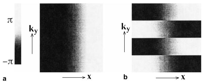
The problem of timing delays is illustrated in Fig. 1. Figure 1a is a phase image of a spin warp data matrix with a one-sample delay in the readout (kx) direction, after Fourier transformation in the readout direction. Figure 1b is the equivalent phase image of an interleaved EPI data set, and clear phase discontinuities can be seen in the ky direction, caused by the alternating direction of echo acquisition. Such discontinuities will cause significant ghost artifacts in the phase-encoding direction (1,2). As an example, Fig. 2 shows a four-interleave axial brain image with (a) and without (b) delay correction.
Figure 1.
a: Phase roll for a spin warp data set will not cause ghosting artifacts. b: Phase rolls for echoes of an echo-planar imaging data set acquired in opposite kx directions, after Fourier transformation in the readout direction. These discontinuities are the principal cause of ghosting artifacts in echo-planar images.
Figure 2.
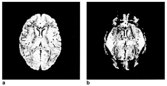
a: Corrected four-interleave echo-planar axial brain image. b: Same image, without correction for a four-sample delay.
Measurement of time delays and phase offsets are often made with “reference scans” as part of the imaging protocol, and post-processing corrections are usually made to correct for these delays. In most reference scans, the phase-encoding blips are turned off, and two or more readout gradient lobes acquire echoes, after one or more RF excitations (1). Jesmanowicz et al (7) have also proposed “internal reference” lines where one additional echo without phase encoding is acquired to measure time delays. The difficulty with most reference methods is that the reference signals are phase modulated by field inhomogeneities and chemical shift. These effects can bias time delay measurement, making such estimates object dependent.
Analog filter delays can also be measured before an imaging protocol, as part of a calibration procedure (8). This calibration is object independent, but only accounts for one part of the total system delay, neglecting delays from digital filters, gradient delays, demodulators, RF coils, etc.
The following discussion begins with a mathematical description of the EPI signal used to generate an image. The first section describes the effects of field inhomogeneities, chemical shift, and hardware time delays and phase offsets. From this analysis, a new object-independent reference method that removes bias from time delay estimates is described.
THEORY
Susceptibility, chemical shift, and Bo field inhomogeneities often have serious and complicated effects on the echo-planar signal. It is the purpose of this section to describe these effects to illustrate the proper way to measure time delays with reference or calibration scans.
Imaging Equation for Echo-planar Signal
Chemical shift and field inhomogeneities are spatially dependent off-resonance effects that can be highly irregular and sample dependent. Field inhomogeneities and susceptibility effects can be described by changes in the static field, ΔB(x, y), while chemical shift can be described by a constant offset, f. An isochromat located at position (x, y) will accrue phase from these off-resonance effects, affecting the k-space raw data matrix. For an interleaved EPI acquisition with ni interleaves, Ny phase-encoding steps, and echo time shifting (ETS) (9), the total signal for the object from echoes acquired in the positive kx direction (+) or negative kx direction (-) is
| (1) |
where ny is the phase-encoding index (ny = (-Ny/2),..., (Ny/2) - 1 for spin-echo EPI, and ny = 0,..., Ny - 1 for gradient-echo EPI), Δky = γGyty is the step size between phase-encoding lines, Gx is the magnitude of the readout gradient, Tro is the time required for a complete readout trapezoid, ρm(x, y) is the density of protons in chemical species m, having an off-resonance shift of fm, and kx is the position in the readout direction, rastering in two directions (±) for + echoes and - echoes.
The first exponential term in the integrand of Eq. (1) reveals a distortion in the x-direction due to inhomogeneities and chemical shift. Since the distortion alternates for oppositely acquired echoes, ghosting artifacts can result from this effect in theory. In practice, however, the readout gradient is sufficiently strong to make this effect small. For example, a 100 Hz off-resonance offset with Gx = 2 G/cm, will cause an alternating spatial shift of 0.7 mm. This is a relatively small shift of a large resonance offset, and for this reason this distortion will be ignored from here on.
The distortion term in the second exponential term, however, is substantial since the time to play a readout trapezoid (Tro) is large, and the area under a phase-encoding blip (niGyty) is small. Unlike sampling in the readout direction, sampling in the phase-encoding direction is most often incremented unidirectionally. Consequently, no discontinuities arise, and no ghosting artifacts will result from this effect. Increasing the number of interleaves reduces distortion and the effects of chemical shift, as does reducing the readout trapezoid time.
System Filter Response
The raw MR signal detected by the RF receive coil must pass through several stages before the final discretized echo is stored in the raw k-space data matrix. Gradient hardware, preamplifiers, analog filters, demodulators, and digital filters are all part of this causal system that can introduce time delays to the MR signal. In standard spin-warp imaging, these distortions are of little consequence, as all ky lines are acquired in the same direction, and this phase information is not displayed in magnitude images. In EPI and GRASE sequences, data are sampled as the position in k-space rasters back and forth in the kx direction. This implies that different ky lines are acquired in opposing directions, and the “system filter response” will cause significant phase discontinuities in the phase-encoding direction, resulting in ghosting artifacts (1,2). Mathematically, the k-space signal, s±(kx, nyΔky) is convolved with the system filter response, h(kx),
| (2) |
where *kx denotes convolution in the kx direction. Fourier transformation in this direction,
| (3) |
where x ∈ (-FOV/2, FOV/2) and is the Fourier transform of a ky line acquired in the ±kx direction. If the magnitude of the system response is even symmetric, it can be ignored, and H(±x) ≡ e±jψ(x), where ψ(x) is the phase of the system filter response. For a system with a linear phase response, ie, a simple time delay, ψ(x) = γGx(tox + ϕ), where to is the system time delay, and ϕ is a constant phase offset. Upon Fourier transformation of Eq. (1),
| (4) |
where chemical shift has been ignored. If the delay, to, and offset, ϕ, are known or can be measured, then the image data set can be corrected by multiplying Eq. (4) by e±jγGx(tox+ϕ) before Fourier transformation in the phase-encoding direction. Although distortion in the phase-encoding direction will still be present, ghosting artifacts resulting from system delays will have been removed.
MATERIALS AND METHODS
Reference Scans for Scanner Delay Estimation
Reference scans are often used to measure system time delays. Eq. (4) is very useful in describing the behavior of reference scans, which are used to measure system time delays. In a reference scan, multiple lines of k-space data are acquired sequentially, with the phase-encoding blips turned off (Δky = 0). From Eq. (4), the signal for the nth echo of the reference scan can be written,
| (5) |
or
| (6) |
where M(x, n) and A(x, n) are the magnitude and phase of the integral of Eq. (5), respectively.
Standard reference scans (1,10) acquire one or more echo trains without phase encoding. After appropriate time reversal and one-dimensional (1D) Fourier transformation, the phase difference (11) of two consecutive profiles in the echo train is
| (7) |
and the time delay and constant offset can be estimated as
| (8) |
where * denotes complex conjugation, and S±(x, n) and S±(x, n + 1) are the nth and n + 1th profile of the reference raw data, respectively. The additional phase from the inhomogeneities will confound attempts to measure to and ϕ through linear regression, and estimates of to and ϕ will be object dependent. If these values are used to correct the raw data, the bias will prevent proper delay correction.
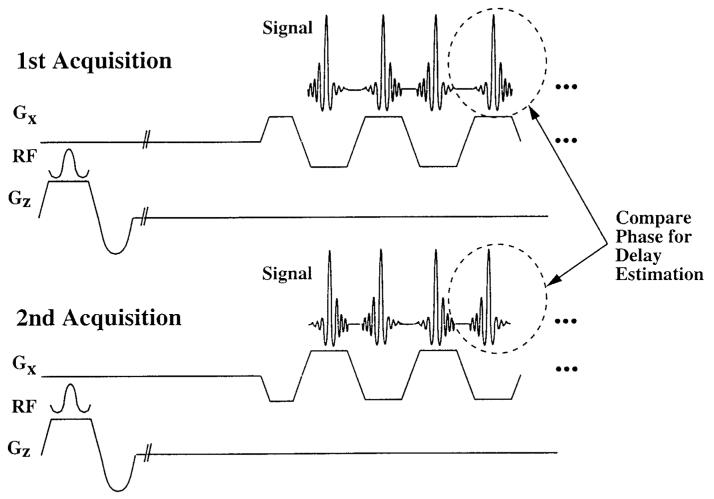
As an alternative, we propose a “balanced” reference scheme whereby two separate reference acquisitions are acquired. The first acquisition is the same as the standard reference, while the second is identical to the first, except that the polarity of the entire readout gradient train has been reversed, as shown in Fig. 3. In this case, the phase difference leads to an estimator where the effects of inhomogeneities have been removed,
| (9) |
where S±(x, n) is the nth profile acquired after the first excitation, and S∓(x, n) is the nth profile acquired after the second excitation with the readout gradient polarity reversed.
Figure 3.
Balanced reference scan technique. In the first acquisition, the readout echo train acquires standard reference data with no phase-encoding blips. The second acquisition is identical, except that the polarity of the readout gradient is reversed, as shown. Comparison of echoes acquired at the same time after RF excitation will remove bias from inhomogeneities.
The bias will be removed so long as the readout gradient is symmetric and the two profiles that are compared have been acquired at the same time after the RF excitation. This ensures that the phase of off-resonance spins has evolved by the same amount, removing potential time delay bias. Any estimation method that satisfies these conditions will not be confounded by field inhomogeneities, making it possible to make a complete delay estimate after only two RF excitations.
As recently described by our group and others (12, 13, 14), effective time delays in the logical readout direction depend on image plane orientation. This dependence is caused by anisotropic gradient delays, where the effective time delay is a weighted average of delays along the orthogonal axes. In addition, anisotropic delays cause alternating shifts in the phase-encoding direction that bias delay measurements made through reference scans. Explicitly, the nth profile of a reference scan in oblique coordinates is
| (10) |
where ±δky is the alternating phase encoding resulting from anisotropic gradient delays. Since this additional encoding alternates between + echoes and - echoes, the bias it creates will be removed by neither the standard nor the balanced reference method described above. Therefore, reference scans in oblique planes should be avoided.
Imaging
All experiments were performed on a GE Signa 1.5 T Horizon (version 5.5) scanner, which has shielded gradients with maximum gradient strength of 2.2 G/cm and slew rate of 120 T/msec on all three axes. Manufacturer interleaved EPI sequences were also used to make scanner delay measurements, shown in the following sections.
RESULTS
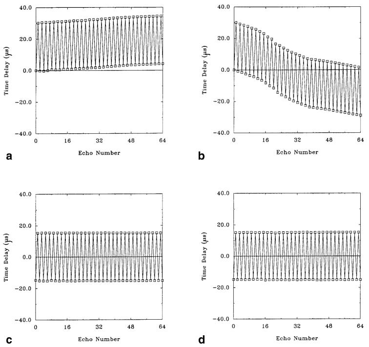
Figure 4 plots the effective time delays in the readout direction calculated for the first 64 echoes, from a single-shot gradient-echo EPI raw data matrix with no phase encoding. In Fig. 4a, the estimates were made using the standard reference estimation method in a water phantom, where all time delays are referenced to the first echo. Despite shimming and the use of a homogeneous water phantom, an increasing drift of these estimates is apparent, resulting from field inhomogeneities. In Fig. 4b, the estimates were made using the standard reference estimation method in a subject’s brain. The trend of the delays is nonlinear, and an average delay is not apparent, demonstrating the object-dependent nature of the standard estimation method.
Figure 4.
Time delays (in μsec) plotted against phase-encoding index for a single-shot EPI data set (first 64 echoes). a: Standard reference scan in a water phantom. Time delays were measured with respect to the first echo. b: Standard reference scan in the brain. The trend of the delays is nonlinear, and an average delay is not apparent. c: Balanced reference scan in a water phantom. Time delays were calculated using opposite polarity readout gradients, eliminating the delay bias. The average delay is 15.0 μsec. d: Balanced reference scan in the brain. The data are nearly identical to those obtained in the water phantom, and the average delay is also 15.0 μsec.
Figure 4c plots the time delays made in a water phantom estimated from the balanced reference method described in the Methods section. Each time delay is made by comparison of the echoes from the two data sets occurring at the same time after RF excitation. The time delays show no drift and are constant across all echoes, indicating excellent time delay stability. The average time delay for this gradient orientation is 15.0 μsec, determined from the average of the delays for the + echoes and - echoes. Averaging in this way removes potential bias from imperfect readout gradient prephasers. Figure 4d plots the time delays made in a subject’s brain estimated from the balanced reference method. The data are very similar to that obtained in the water phantom (Fig. 4c) by the balanced reference scan method, and the average delay is also 15.0 μsec, illustrating the object independence of the balanced reference scan method.
Figure 5 shows reconstructed images for single-shot EPI data using the reference data shown in Fig. 4. Figure 5a was reconstructed using the standard reference data shown in Fig. 4b, and there is significant ghosting. Figure 5b was reconstructed using the balanced reference data for a water phantom shown in Fig. 4d, and although minor ghosting remains, it has been reduced substantially. Figure 5c was reconstructed using the balanced reference data for the brain shown in Fig. 4c, and there is no significant difference between it and Fig. 5b.
Figure 5.
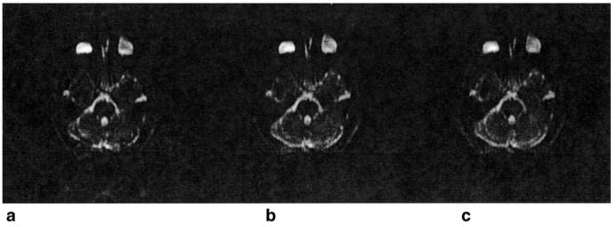
Reconstructed images for single-shot EPI data using the reference data shown in Fig. 4. a: Image using the standard reference data shown in Fig. 4b. Note the significant ghosting. b: Image using the balanced reference data shown in Fig. 4c. Although minor ghosting remains, it has been reduced substantially. The windowing has been adjusted equally on each image to emphasize the ghosting. c: Image using the balanced reference data for the water phantom shown in Fig. 4c. Note that there are no significant differences between this image and the image shown in b.
DISCUSSION
In this work, a description of the EPI signal and the effects of field inhomogeneities and system time delays on this signal was presented. It was shown that proper time delay correction will eliminate ghosting artifacts, even in the presence of moderate field inhomogeneities. Distortion in the phase-encoding direction will still be present, however.
From this analysis, a novel balanced reference estimation technique for measurement of these delays was formulated. This estimator was shown to be effective in removing time delay biases caused by off-resonance effects. Using this reference method, it was shown experimentally that system time delays were independent of the objects scanned and that these delays were stable during a readout echo train.
In the presence of anisotropic gradient delays, reference scans should be avoided to prevent orientation-dependent bias on time delay estimates. The balanced reference scan is useful, however, in systems with anisotropic gradient delays, as part of a calibration procedure. Delay correction for acquisitions in oblique coordinates can then be performed using “compensation blips,” as recently described (14).
ACKNOWLEDGMENTS
We gratefully acknowledge helpful discussions with Bradley Bolster, MSE. We also thank Adam B. Kerr, MASc, and Walter Block, PhD, of Stanford University for information on off-line data processing. E.A. is supported by a Whitaker Foundation Biomedical Research Grant, S.B.R. is supported by a Medical Scientist Training Program (MSTP) Fellowship, and E.R.M. is an Established Investigator of the American Heart Association.
Grant sponsor: NIH; Grant number: HL45683; Grant sponsors: Whitaker Foundation, Medical Scientist Training Program, and the American Heart Association.
REFERENCES
- 1.Bruder H, Fischer H, Reinfelder HE, Schmitt F. Image reconstruction for echo planar imaging with non-equidistant k-space sampling. Magn Reson Med. 1992;23:311–323. doi: 10.1002/mrm.1910230211. [DOI] [PubMed] [Google Scholar]
- 2.Reeder SB, Atalar E, Bolster BD, McVeigh ER. Quantification and reduction of ghosting artifacts in interleaved echo planar imaging. Magn Reson Med. 1997;38:429–439. doi: 10.1002/mrm.1910380312. [DOI] [PMC free article] [PubMed] [Google Scholar]
- 3.Oshio K, Feinberg DA. GRASE (gradient- and spin-echo) imaging: a novel fast MRI technique. Magn Reson Med. 1991;20:344–349. doi: 10.1002/mrm.1910200219. [DOI] [PubMed] [Google Scholar]
- 4.Noll DC, Nishimura DG, Macovski A. Homodyne detection in magnetic resonance imaging. IEEE Trans Med Imaging. 1991;10:154–163. doi: 10.1109/42.79473. [DOI] [PubMed] [Google Scholar]
- 5.Oppenheim AV, Shafer RW. Discrete time signal processing. Prentice Hall; Englewood Cliffs, NJ: 1982. [Google Scholar]
- 6.Ahn CB, Cho ZH. Analysis of eddy currents in nuclear magnetic resonance imaging. Magn Reson Med. 1991;17:149–163. doi: 10.1002/mrm.1910170119. [DOI] [PubMed] [Google Scholar]
- 7.Jesmanowicz A, Wong EC, Hyde JS. Phase correction for EPI using internal reference lines. Book of Abstracts; 12th Annual Meeting of SMRM; 1993.p. 1239. [Google Scholar]
- 8.King KF, Crawford CR, Maier JK. Correction for filter induced ghosts in echo planar imaging. Book of Abstracts; 3rd Annual Meeting of SMR; 1995.p. 105. [Google Scholar]
- 9.Feinberg DA, Oshio K. Phase errors in multi-shot echo planar imaging. Magn Reson Med. 1994;32:535–539. doi: 10.1002/mrm.1910320418. [DOI] [PubMed] [Google Scholar]
- 10.Wan X, Gullberg GT, Parker DL, Zeng GL. Reduction of geometric distortion and intensity distortions in echo-planar imaging using a multireference scan. Magn Reson Med. 1997;37:932–944. doi: 10.1002/mrm.1910370619. [DOI] [PubMed] [Google Scholar]
- 11.Bryant DJ, Payne JA, Firmin DN, Longmore DB. Measurement of flow with NMR imaging using a gradient pulse and phase difference technique. J Comput Assist Tomogr. 1984;8:588–593. doi: 10.1097/00004728-198408000-00002. [DOI] [PubMed] [Google Scholar]
- 12.Zhou X, Epstein FH, Maier JK. Reduction of a new Nyquist ghost in oblique echo planar imaging; Fourth Annual Meeting of ISMRM; 1996.p. 1477. [Google Scholar]
- 13.Gatehouse PD, Hughes RL, Yang GZ, Firmin DN. The effect of different gradient axis delays on oblique echo-planar imaging; Fourth Annual Meeting of the ISMRM; 1996.p. 1481. [Google Scholar]
- 14.Reeder SB, Atalar EA, Faranesh AZ, McVeigh ER. Referenceless interleaved echo-planar imaging. Magn Reson Med. 1999;41:87–94. doi: 10.1002/(sici)1522-2594(199901)41:1<87::aid-mrm13>3.0.co;2-x. [DOI] [PMC free article] [PubMed] [Google Scholar]


