Abstract
During mitosis, the connections of microtubules (MTs) to centrosomes and kinetochores are dynamic. From in vitro studies, it is known that the dynamic behavior of MTs is related to the structure of their ends, but we know little about the structure of MT ends in spindles. Here, we use high-voltage electron tomography to study the centrosome- and kinetochore-associated ends of spindle MTs in embryonic cells of the nematode, Caenorhabditis elegans. Centrosome-associated MT ends are either closed or open. Closed MT ends are more numerous and are uniformly distributed around the centrosome, but open ends are found preferentially on kinetochore-attached MTs. These results have structural implications for models of MT interactions with centrosomes.
Keywords: Caenorhabditis elegans; centrosome; electron tomography; mitosis; 3-D reconstruction
Introduction
In animal cells, microtubules (MTs) commonly grow from centrosomes (for a review see Doxsey, 2001). Following polymer nucleation, each MT minus end generally remains attached to the centrosome, whereas the plus ends extend out into the cytoplasm (reviewed in Wittmann et al., 2001). In interphase, the minus ends tend to be stable; they do not lose or gain tubulin subunits, and most tubulin turnover takes place at the plus ends. In mitosis, much of the MT turnover is still at the plus ends, but the dynamics of minus ends becomes more complex. At least some of the minus ends lose subunits while remaining attached to the spindle pole, which results in MT movement that has been called flux (for a review see Wittmann et al., 2001). Work in vitro and in vivo has shown that changes in the dynamic properties of MTs are associated with changes in the structure of the ends (for a review see Howard and Hyman, 2003). For instance when MT plus ends are viewed in vitreous ice, growing ends appear as a curved sheet of protofilaments; shrinking ends contain bent or “peeling” protofilaments, known as “rams horns” (Mandelkow et al., 1991; Chrétien et al., 1995). Less work has been done on the structure of minus ends. MTs nucleated in vitro from γ-tubulin, the key regulator of MT nucleation, contain a cone-shaped cap at their minus ends (Keating and Borisy, 2000; Moritz et al., 2000; Wiese and Zheng, 2000). Similar capped structures were previously seen at the minus ends of MTs nucleated from isolated spindle pole bodies of budding yeast (Byers et al., 1978; Rout and Kilmartin, 1990; Bullitt et al., 1997) and centrosomes from Drosophila cells (Moritz et al., 1995), suggesting that these polymers too are nucleated and capped by the γ-tubulin complex. It is plausible that MTs nucleated from γ-tubulin complexes are stabilized by this minus-end cap. However, we know little about the distribution of minus-end structures at mitotic spindle poles in vivo. The only study to date was in budding yeast cells where all minus ends were found to be capped by structures that resemble the γ-tubulin nucleated ends seen in vitro (O'Toole et al., 1999). No data are currently available for MT minus ends in mitotic animal cells. Are there morphologically distinct structures, which could potentially account for the dynamic properties of minus ends attached to a mitotic animal spindle pole? Here, we use high-pressure freezing and electron tomography to examine the end structure of MTs in mitotic spindles of cells from Caenorhabditis elegans embryos. We have found variation in centrosome-proximal MT end morphology that is systematically related to the position of the MT plus end and may reflect different mechanisms by which a minus end can be bound to a centrosome.
Results and discussion
Distribution of MT ends in the centrosome
The centrioles in C. elegans are morphologically simple (Wolf et al., 1978; Albertson, 1984; O'Connell et al., 2001; Kirkham et al., 2003), but they appear to duplicate and function in a conventional manner (for review see O'Connell, 2000). To characterize the structure of centrosome-proximal MT ends and their distribution to the C. elegans centrioles we have examined the overall distribution of MT ends in the vicinity of spindle poles in metaphase and anaphase (Fig. 1). A typical array of MTs can be detected in the pericentriolar material (PCM), but MTs do not physically touch the centriole pair. To analyze the MT arrangement, we marked the pole-proximal end of each MT in the reconstructed volumes (Fig. 1, B and E). From these models, it is clear that MTs are centered predominantly around one centriole, which we have designated the “mother” (marked in light blue in Fig. 1).
Figure 1.
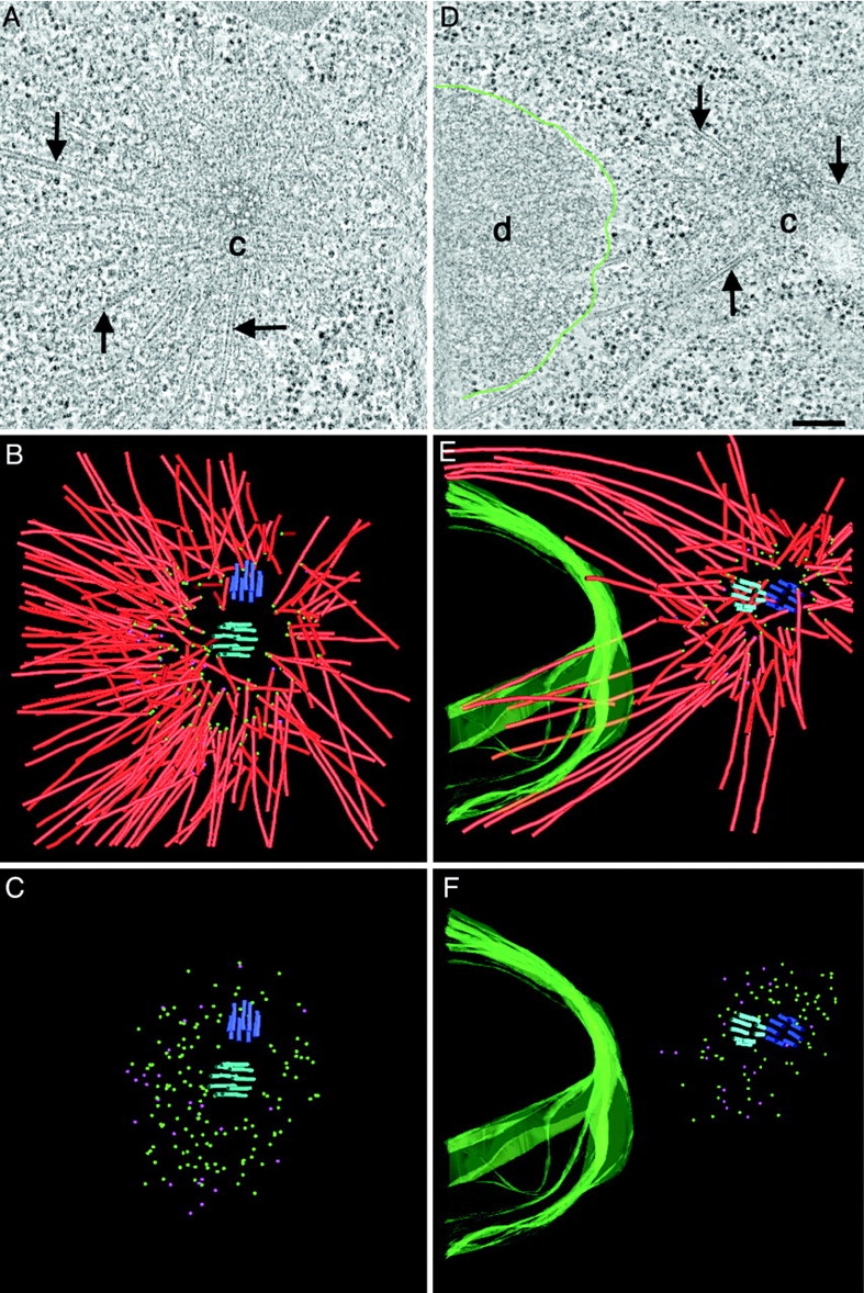
MT ends at the centrosome are either closed or open. Distribution of MT minus ends around centrioles in metaphase (A–C) and anaphase (D–F). (A and D) Selected tomographic slices showing MTs (arrows), the centrosome (c), and the condensed DNA (d, DNA surface outlined in green). (B and E) Corresponding 3-D models showing the centrioles (blue and purple), the MTs (red) and the surface of the chromatin (green). MT minus ends are marked by spheres. (C and F) Models showing the distribution of closed (green) and open (purple) MT minus ends. Bar, 200 nm. Also, see Videos 1–4, available at http://www.jcb.org/cgi/content/full/jcb.200304035/DC1.
We then characterized the structure of the centrosome-associated MT ends at higher resolution and found two types embedded in the PCM: the majority of the ends were closed by a cap, but many MT ends were open. Galleries of pole-proximal MT ends are shown in Fig. 2, A and B. The closed ends typically were conical, whereas the open ends were blunt or flared. At some open ends, we observed single or double sheet-like extensions whose curvature varied. None of these open-end morphologies suggested the presence of a protein complex distinct from tubulin subunits. The capped cone-shaped ends, on the other hand, are reminiscent of minus ends observed at yeast spindle pole bodies (Byers et al., 1978; Rout and Kilmartin, 1990; Bullitt et al., 1997; O'Toole et al., 1999) and at isolated Drosophila centrosomes (Moritz et al., 1995).
Figure 2.
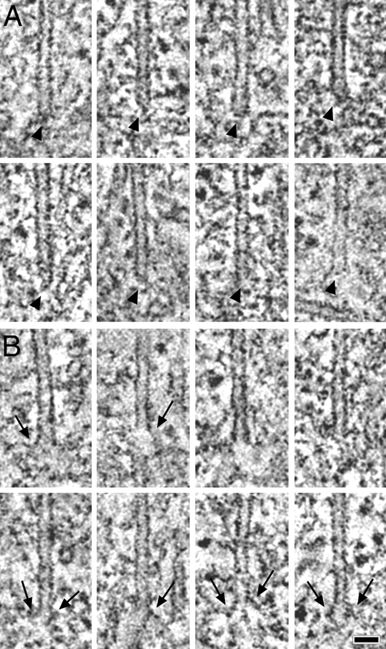
Closed MT minus ends are pointed, open ends are blunt or slightly flared. (A) Capped minus ends. The ends of the MTs are marked by arrowheads. Capped MTs are often pointed and flattened on one side. (B) Open minus ends. Some MT ends show an open, blunt morphology, whereas a few are flared (arrows). Single or double sheet-like extensions can be observed. Bar, 50 nm.
To determine if there was a correlation between MT end structure and position within the centrosome, we marked the closed and open ends in our tomographic volumes with green and purple spheres, respectively (Fig. 1, C and F). The capped MT ends were distributed evenly around the mother centrioles, whereas the open ends were concentrated on one side (the left side in these images). A low magnification view of these cells showed that the chromosomes were also placed to the left of the centrosomes (data not shown). Thus, open MT ends are found preferentially on MTs that point toward the chromosomes.
Fine structure of kinetochore MT (KMT) plus ends
We have used electron tomography to ask whether different minus end structures are associated with specific subpopulations of spindle MTs. First, we identified chromatin-associated ends of spindle MTs. In C. elegans this interaction occurs in a ribosome-free zone that surrounds each chromosome (Howe et al., 2001). When chromatin is aligned on the metaphase plate, the two pole-facing regions are peppered with MT ends (Fig. 3 A). In the corresponding three-dimensional (3-D) model, 118 MTs were identified (Fig. 3 B). 85 of these MTs terminated in the ribosome-free zone at the face of the condensed chromatin and were considered to be kinetochore MTs (KMTs). At 6–10 nm resolution we have found no distinct electron-dense protein complex physically linking chromatin to the MTs. Instead, there was a gap between the MT plus ends and the apparent surface of the chromatin. This gap contained a loose mat of fine filaments. KMT ends lay at a mean (±SD) distance from the chromatin surface of 115 (±52) nm. The mean width of the ribosome-free zone was 194 (±45) nm. Interestingly, the kinetochores of PtK1 cells prepared by high-pressure freezing/freeze-substitution have been reported to contain a “ribosome-excluded” zone 100–150-nm wide (McEwen et al., 1998), which is similar in appearance and dimension to the zone described here.
Figure 3.
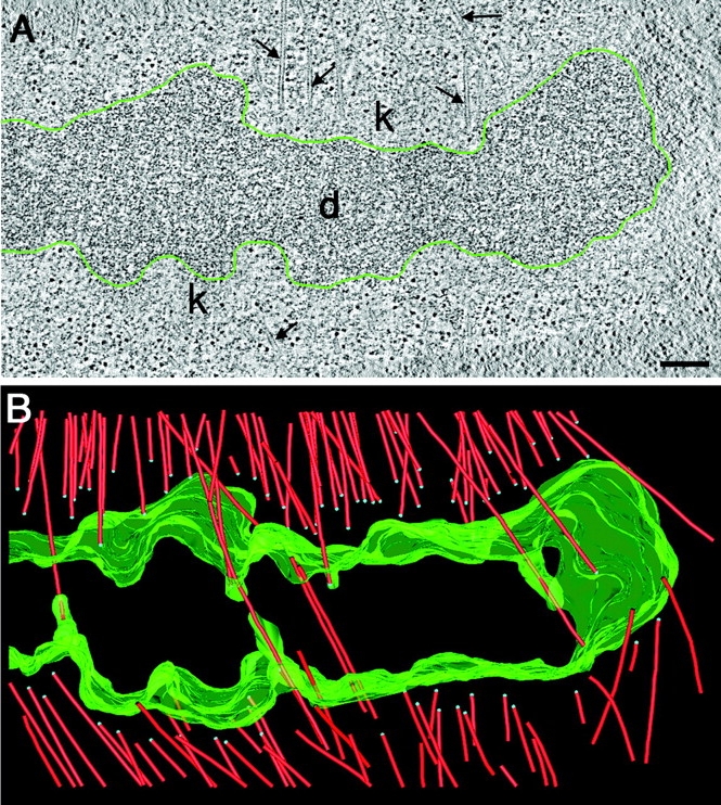
KMTs do not end directly on the condensed chromatin. (A) Selected 2.7-nm thick tomographic slice showing a region at the metaphase plate. MTs (arrows) and the kinetochore regions (k) are indicated. The surface of the DNA (d) is outlined in green. (B) Corresponding 3-D model showing MTs (red) and the surface of the chromatin (green). MT plus ends are marked by blue spheres. Bar, 500 nm. Also, see Videos 5 and 6, available at http://www.jcb.org/cgi/content/full/jcb.200304035/DC1.
The morphological distinctions at the MT minus ends prompted us to investigate the chromosome-associated end morphologies. Fig. 4 A shows a higher magnification tomographic slice from the kinetochore region shown in Fig. 3. Several KMTs can be seen; their ends immersed in the ribosome-free zone. A 3-D model of this region is displayed in Fig. 4 B, and galleries of KMT-proximal ends are shown in Fig. 4, C and D. Of 83 plus ends analyzed in this tomographic volume, all were open, and 78% were flared to some extent. Flared ends often showed an electron-dense extension from one or both sides of the MT end. A flared morphology was also observed in late anaphase cells (data not shown). Some KMT plus ends (22%) appeared blunt, but there were no capped MT ends in the kinetochore region.
Figure 4.
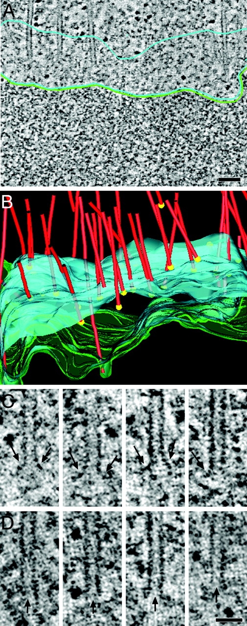
KMT plus ends have an open, flared, or blunt morphology. (A) Detail of a kinetochore region as obtained by high-voltage electron tomography. KMTs terminate in the ribosome-free zone (outlined in light blue). The chromatin surface is indicated by a green line. (B) 3-D model of the kinetochore region showing MTs (red), the position of their plus ends (yellow spheres), the outer boundary of the ribosome-free zone (blue), and the surface of the DNA (green). The mean width of the ribosome-free zone is 194 nm (±45 nm), and the mean distance of the MT plus end to the chromatin is 115 nm (±52 nm). Also, see Video 7, available at http://www.jcb.org/cgi/content/full/jcb.200304035/DC1. (C) KMT plus ends with an open, flared morphology. Electron tomography revealed double or single extensions (arrows) at the plus ends. (D) Plus ends with an open, blunt morphology. The ends of the open tubes are marked by arrows. Bars: (A) 100 nm; (C) 50 nm.
Connecting KMT plus and minus ends in 3-D
We next looked at the minus end structures of KMTs. KMTs were tracked through tomographic reconstructions from their plus ends at the chromosomes to their minus ends in the PCM. 3-D models generated from two serial, tomographic volumes are shown in Fig. 5. The complete model with presumptive KMTs (white, n = 48) and nonKMTs (red, n = 520) illustrates the density of MTs forming the mitotic spindle and the arrangement of the spindle fibers by which chromatin is connected to the centrosome (Fig. 5 A). Non-KMTs were defined as those MTs whose pole-distal ends lay outside the ribosome-free zone or were not within the volume of the tomogram (though some of the latter may, of course, be KMTs). This partial metaphase reconstruction was first used to perform a neighbor density analysis (Mastronarde et al., 1993) to determine if there were preferred interfiber distances between any of the spindle MTs. A peak in the distribution of interfiber distance has been considered indicative of interactions between those fiber classes, as has been observed in the non-KMT–KMT interfiber distances in PtK1 spindles (McDonald et al., 1992). We also found no evidence for a preferred spacing between the MTs in a C. elegans spindle (data not shown), suggesting that KMTs do not form bundles, as seen in cells of more complex animals. This is presumably because the kinetochores of C. elegans are holocentric and the plus-end binding sites are distributed along the chromosomes. In support of this idea, no bundling was seen in the hemipteran insect Agallia constricta, which also has holocentric kinetochores (Rieder et al., 1990).
Figure 5.
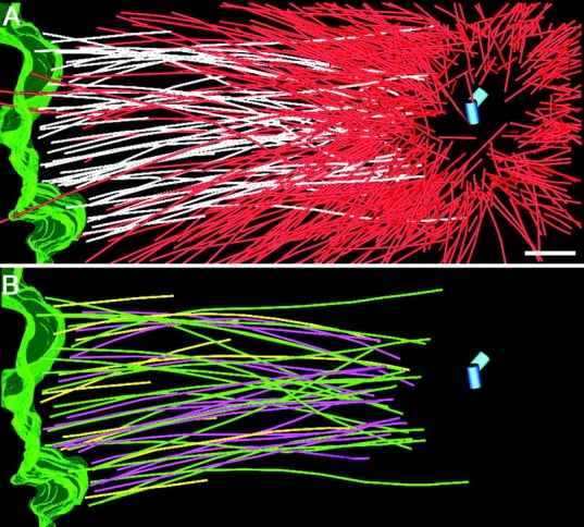
Half of the KMT minus ends are open. (A) Partial reconstruction of a metaphase spindle. The surface of the DNA is outlined in green, and MTs that end in the ribosome-free zone are identified in white. Other spindle MTs are shown in red. The centriole pair is shown as blue cylinders. The mean distance from the mother centriole to the open MT minus end (558 ± 139 nm) was not significantly different from the mean distance of closed MT minus ends (530 ± 137) from the mother centriole. (B) KMTs with closed (green) and open (magenta) minus ends. KMTs with minus ends “outside” the volume of the reconstruction are shown in yellow. Bar, 500 nm. Also, see Video 8, available at http://www.jcb.org/cgi/content/full/jcb.200304035/DC1.
We then examined the minus-end structure for those KMTs that could be traced unambiguously from the chromatin to the centrosome (Fig. 5 B). 50% of these KMTs had a closed minus end (n = 19), whereas 50% were open (n = 18). In contrast, only 20% of all the MTs show open pole-proximal ends. Open minus ends are therefore preferentially associated with kinetochore-attached MTs. Since we are unable to trace the final termination of all centrosomes/MTs in this reconstruction, it is possible that all MTs with open minus ends are KMTs. More complete structural data will be needed to test this possibility.
What is the functional consequence of these different minus-end structures? It seems likely that the capped ends are stable minus ends, nucleated from the centrosome. γ-tubulin appears to be the kinetically dominant nucleator of mitotic centrosomes in C. elegans (Hannak et al., 2002), suggesting that these minus ends are capped by γ-tubulin during nucleation. Interestingly, the capped ends make up the majority (∼80%) of the minus ends. Open ends, on the other side, are likely to be dynamic, perhaps accounting for the dynamic properties of minus ends at spindle poles. The open minus-end structure could be a structural consequence of MT severing where release of the γ-tubulin cap could then lead to more dynamic behavior of the MT minus ends. MT severing by katanin-like proteins has been documented in meiotic spindles of C. elegans, to serve a possible role in limiting the size of MTs in these smaller spindles (Srayko et al., 2000), as well as in mitotic spindles from other systems (McNally et al., 1996; McNally and Thomas, 1998). Possibly, open MTs do not associate with nucleating sites but rather with structures capable of force generation and MT disassembly activity in the PCM. Such ends could be generated by release and anchoring of centrosome-nucleated MTs (for reviews see Bornens, 2002; McIntosh et al., 2002). Dynamic MT minus ends could also participate in poleward MT flux of mitotic spindles (for review see Wittmann et al., 2001). Future experiments combining RNA-mediated interference (RNAi) and tomographic reconstruction of different spindles should distinguish these different possibilities.
Materials and methods
Specimen preparation for electron microscopy
Wild-type C. elegans hermaphrodites were cryoimmobilized using a BAL-TEC HPM 010 high-pressure freezer (BAL-TEC). Fixation was performed by freeze substitution over 3 d at −90°C in anhydrous acetone containing 1% OsO4 and 0.1% uranyl acetate (EM AFS; Leica) (McDonald and Müller-Reichert, 2002). Epon/Araldite infiltrated samples were flat embedded in a thin layer of resin and polymerized for 3 d at 60°C (Rappleye et al., 1999). Worms containing >5 early embryos were selected by light microscopy before remounting. Serial semithick sections (300–400 nm) were cut using a Leica Ultracut UCT Microtome. Sections were collected on Formvar-coated copper slot grids and poststained with 2% uranyl acetate in 70% methanol and Reynold's lead citrate.
High-voltage electron tomography
Electron tomography was performed essentially as described in O'Toole et al. (1999). Briefly, 15-nm colloidal gold particles (Sigma-Aldrich) were attached to both surfaces of the semi-thick sections to serve as fiducial markers for subsequent image alignment. The specimens were placed in a tilt-rotate specimen holder (Model 650; Gatan, Pleasanton, CA) and tomographic datasets recorded using a JEM-1000 high-voltage electron microscope (JEOL, USA) operated at 750 kV. Images were captured every 1.5° over a ± 60° range using a Gatan 1K × 1K CCD camera at a pixel size of 1.4 nm. In some instances, montages of 2 × 1 or 3 × 1 frames were collected and used to image larger areas (Marsh et al., 2001). For dual axis tomography, the grids were imaged in one tilt series then rotated 90°, and a similar tilt series was acquired. For image processing, images were transferred to a Silicon Graphics workstation, and the tilted views were aligned using the positions of the colloidal gold particles as fiducial points. Tomograms were computed for each tilt axis using the R-weighted back-projection algorithm (Gilbert, 1972). We used the ratio of the section thickness, as defined by the microtome's setting, to the section's thickness measured after microscopy to calculate a “thinning factor,” which was then used to correct the tomogram's dimension along the beam axis (O'Toole et al., 1999). For double tilt data sets, the two tomograms were aligned to each other and combined (Mastronarde, 1997). In addition, tomograms computed from adjacent serial sections were aligned and joined to increase the reconstructed volume (Ladinsky et al., 1999; Marsh et al., 2001). We recorded 11 double tilt series of mitotic spindles. In total, we analyzed 5 mitotic centrosomes.
Modeling and analysis of tomographic data
Tomograms were displayed and analyzed using the IMOD software package (Kremer et al., 1996). Features of interest were modeled in the serial slices extracted from the tomogram. An “image slicer” window in IMOD was used to display a slice extracted from the 3-D volume in any position or orientation; this feature was useful for unambiguous tracking of MTs in 3-D (O'Toole et al., 1999). With the slicer window, we analyzed the morphology of MT ends near the centrosomes and kinetochores by extracting a slice of image data 1-voxel thick and adjusting its orientation to contain the axis of the MT in a single view (O'Toole et al., 1999). A projection of the 3-D model was displayed and rotated to study its 3-D geometry. For this display in 3-D, MTs were shown as tubular graphic objects.
A program was written to compute the distance between the points on a selected object and a chosen reference location. The centroid of each centriole was located and used as the reference for positions within the spindle. A single model point was located at the pole-proximal end of each MT, and the 3-D distance of those points from the reference was calculated. A neighbor density analysis was performed to determine if there were preferred inter-fiber distances. These have been seen as indicative of interactions between different classes of MTs in two (McDonald et al., 1992) and three dimensions (Mastronarde et al., 1993, Marsh et al., 2001). MT ends were classified as described (Müller-Reichert et al., 1998).
Online supplemental material
Supplemental videos are available at http://www.jcb.org/cgi/content/full/jcb.200304035/DC1. Videos 1 and 2 show the complete tomographic volume of centrosomes in metaphase and anaphase corresponding to Fig. 1, A and D, respectively. Videos 3 and 4 are the projected 3-D models corresponding to Fig. 1, B and C, and E and F, respectively. Video 5 corresponds to Fig. 3 A and shows the tomographic reconstruction of a kinetochore region in metaphase, and Video 6 shows the projected 3-D model displayed in Fig. 3 B. The video sequence associated with Fig. 4 B (Video 7) shows a movie through a tomographic reconstruction of a kinetochore region in greater detail. Video 8, corresponding to Fig. 5, A and B, illustrates the tracing of KMTs in a partially reconstructed metaphase spindle.
Supplemental Material
Acknowledgments
We thank Drs. Carrie Cowan, Laurence Pelletier, and Martin Srayko for a critical reading of the manuscript and Drs. Ivan Baines, Michaela Wilsch-Bräuninger, and Paul Verkade for helpful conversations about this work. Drs. David Mastronarde and Richard Gaudette provided essential application software.
This work was supported in part by grant RR00592 from the National Center for Research Resources of the National Institutes of Health to J.R. McIntosh, who is a Research Professor of the American Cancer Society.
The online version of this article includes supplemental material.
Abbreviations used in this paper: 3-D, three-dimensional; KMT, kinetochore MT; MT, microtubule; PCM, pericentriolar material.
References
- Albertson, D.G. 1984. Formation of the first cleavage spindle in nematode embryos. Dev. Biol. 101:61–72. [DOI] [PubMed] [Google Scholar]
- Bornens, M. 2002. Centrosome composition and microtubule anchoring mechanisms. Curr. Opin. Cell Biol. 14:25–34. [DOI] [PubMed] [Google Scholar]
- Bullitt, E., M.P. Rout, J.V. Kilmartin, and C.W. Akey. 1997. The yeast spindle pole body is assembled around a central crystal of Spc42p. Cell. 89:1077–1086. [DOI] [PubMed] [Google Scholar]
- Byers, B., K. Shriver, and L. Goetsch. 1978. The role of spindle pole bodies and modified microtubule ends in the initiation of microtubule assembly in Sacharomyces cerevisiae. J. Cell Sci. 30:331–352. [DOI] [PubMed] [Google Scholar]
- Chrétien, D., S.D. Fuller, and E. Karsenti. 1995. Structure of growing microtubule ends: two-dimensional sheets close into tubes at variable rates. J. Cell Biol. 129:1311–1328. [DOI] [PMC free article] [PubMed] [Google Scholar]
- Doxsey, S. 2001. Re-evaluating centrosome function. Nat. Rev. Mol. Cell Biol. 2:688–698. [DOI] [PubMed] [Google Scholar]
- Gilbert, P.F.C. 1972. The reconstruction of a three-dimensional structure from projections and its application to electron microscopy. II. Direct methods. Proc. R. Soc. Lond. B. Biol. Sci. 182:89–102. [DOI] [PubMed] [Google Scholar]
- Hannak, E., K. Oegema, M. Kirkham, P. Gönczy, B. Habermann, and A.A. Hyman. 2002. The kinetically dominant assembly pathway for centrosomal asters in Caenorhabditis elegans is γ-tubulin dependent. J. Cell Biol. 157:591–602. [DOI] [PMC free article] [PubMed] [Google Scholar]
- Howard, J., and A.A. Hyman. 2003. Dynamics and mechanics of the microtubule plus end. Nature. 422:753–758. [DOI] [PubMed] [Google Scholar]
- Howe, M., K.L. McDonald, D.G. Albertson, and B.J. Meyer. 2001. HIM-10 is required for kinetochore structure and function on Caenorhabditis elegans holocentric chromosomes. J. Cell Biol. 153:1227–1238. [DOI] [PMC free article] [PubMed] [Google Scholar]
- Keating, T.J., and G.G. Borisy. 2000. Immunostructural evidence for the template mechanism of microtubule nucleation. Nat. Cell Biol. 2:352–357. [DOI] [PubMed] [Google Scholar]
- Kirkham, M., T. Müller-Reichert, K. Oegema, S. Grill, and A.A. Hyman. 2003. SAS-4 is a C. elegans centriolar protein that controls centrosome size. Cell. 112:575–587. [DOI] [PubMed] [Google Scholar]
- Kremer, J.R., D.N. Mastronarde, and J.R. McIntosh, Jr. 1996. Computer visualization of three-dimensional image data using IMOD. J. Struct. Biol. 116:71–76. [DOI] [PubMed] [Google Scholar]
- Ladinsky, M.S., D.N. Mastronarde, J.R. McIntosh, K.E. Howell, and L.A. Staehelin. 1999. Golgi structure in three dimensions: Functional insights from the normal rat kidney cell. J. Cell Biol. 144:1135–1149. [DOI] [PMC free article] [PubMed] [Google Scholar]
- Mandelkow, E.M., E. Mandelkow, and R.A. Milligan. 1991. Microtubule dynamics and microtubule caps: a time-resolved cryo-electron microscopy study. J. Cell Biol. 114:977–991. [DOI] [PMC free article] [PubMed] [Google Scholar]
- Marsh, B.J., D.N. Mastronarde, K.F. Buttle, K.E. Howell, and J.R. McIntosh. 2001. Organellar relationships in the Golgi region of the pancreatic beta cell line, HIT-T15, visualized by high resolution electron tomography. Proc. Natl. Acad. Sci. USA. 98:2399–2406. [DOI] [PMC free article] [PubMed] [Google Scholar]
- Mastronarde, D.N., K.L. McDonald, R. Ding, and J.R. McIntosh. 1993. Interpolar spindle microtubules in PTK cells. J. Cell Biol. 123:1475–1489. [DOI] [PMC free article] [PubMed] [Google Scholar]
- Mastronarde, D.N. 1997. Dual-axis tomography: An approach with alignment methods that preserve resolution. J. Struct. Biol. 120:343–352. [DOI] [PubMed] [Google Scholar]
- McDonald, K., and T. Müller-Reichert. 2002. Cryomethods for thin section electron microscopy. Methods Enzymol. 351:96–123. [DOI] [PubMed] [Google Scholar]
- McDonald, K.L., E.T. O'Toole, D.N. Mastronarde, and J.R. McIntosh. 1992. Kinetochore microtubules in PtK1 cells. J. Cell Biol. 118:369–383. [DOI] [PMC free article] [PubMed] [Google Scholar]
- McEwen, B.F., C.-E. Hsieh, A.L. Mattheyses, and C.L. Rieder. 1998. A new look at kinetochore structure in vertebrate somatic cells using high-pressure freezing and freeze substitution. Chromosoma. 107:366–375. [DOI] [PMC free article] [PubMed] [Google Scholar]
- McIntosh, J.R., E.L. Grishchuk, and R.R. West. 2002. Chromosome-microtubule interactions during mitosis. Annu. Rev. Cell Dev. Biol. 18:193–219. [DOI] [PubMed] [Google Scholar]
- McNally, F.J., K. Okawa, A. Iwamatsu, and R.D. Vale. 1996. Katanin, the microtubule-severing ATPase, is concentrated at centrosomes. J. Cell Sci. 109:561–567. [DOI] [PubMed] [Google Scholar]
- McNally, F.J., and S. Thomas. 1998. Katanin is responsible for the M-phase microtubule-severing activity in Xenopus eggs. Mol. Biol. Cell. 9:1847–1861. [DOI] [PMC free article] [PubMed] [Google Scholar]
- Moritz, M., M.B. Braunfeld, J.C. Fung, J.W. Sedat, B.M. Alberts, and D.A. Agard. 1995. Three-dimensional structural characterization of centrosomes from early Drosophila embryos. J. Cell Biol. 130:1149–1159. [DOI] [PMC free article] [PubMed] [Google Scholar]
- Moritz, M., M.B. Braunfeld, V. Guenebaut, J. Heuser, and D.A. Agard. 2000. Structure of the γ-tubulin ring complex: a template for microtubule nucleation. Nat. Cell Biol. 2:365–370. [DOI] [PubMed] [Google Scholar]
- Müller-Reichert, T., D. Chrétien, F. Severin, and A.A. Hyman. 1998. Structural changes at microtubule ends accompanying GTP hydrolysis: information from a slowly hydrolyzable analogue of GTP, guanylyl (α,β)methylenediphosphonate. Proc. Natl. Acad. Sci. USA. 95:3661–3666. [DOI] [PMC free article] [PubMed] [Google Scholar]
- O'Connell, K.F. 2000. The centrosome of the early C. elegans embryo: Inheritance, assembly, replication, and developmental roles. Curr. Top. Dev. Biol. 49:365–384. [DOI] [PubMed] [Google Scholar]
- O'Connell, K.F., C. Caron, K.R. Kopish, D.D. Hurd, K.J. Kemphues, Y. Li, and J.G. White. 2001. The C. elegans zyg-1 gene encodes a regulator of centrosome duplication with distinct maternal and paternal roles in the embryo. Cell. 105:547–558. [DOI] [PubMed] [Google Scholar]
- O'Toole, E.T., M. Winey, and J.R. McIntosh. 1999. High-voltage electron tomography of spindle pole bodies and early mitotic spindles in the yeast Saccharomyces cerevisiae. Mol. Biol. Cell. 10:2017–2031. [DOI] [PMC free article] [PubMed] [Google Scholar]
- Rappleye, C.A., A.R. Paredez, C.W. Smith, K.L. McDonald, and R.V. Aroian. 1999. The coronin-like protein POD-1 is required for anterior-posterior axis formation and cellular architecture in the nematode Caenorhabditis elegans. Genes Dev. 13:2838–2851. [DOI] [PMC free article] [PubMed] [Google Scholar]
- Rieder, C.L., S.S. Bowser, R. Cole, G. Rupp, A. Peterson, and S.P. Alexander. 1990. Diffuse kinetochores and holokinetic anaphase chromatin movement during mitosis in the hemipteran Agallia constricta (Leafhopper) cell line AC-20. Cell Motil. Cytoskeleton. 15:245–259. [DOI] [PubMed] [Google Scholar]
- Rout, M.P., and J.V. Kilmartin. 1990. Components of the yeast spindle and spindle pole body. J. Cell Biol. 111:1913–1927. [DOI] [PMC free article] [PubMed] [Google Scholar]
- Srayko, M., D.W. Buster, O.A. Bazirgan, F.J. McNally, and P.E. Mains. 2000. MEI-1/MEI2 katanin-like microtubule severing activity is required for Caenorhabditis elegans meiosis. Genes Dev. 14:1072–1084. [PMC free article] [PubMed] [Google Scholar]
- Wiese, C., and Y. Zheng. 2000. A new function for the for the γ-tubulin ring complex as a microtubule minus-end cap. Nat. Cell Biol. 2:358–364. [DOI] [PubMed] [Google Scholar]
- Wittmann, T., A. Hyman, and A. Desai. 2001. The spindle: a dynamic assembly of microtubules and motors. Nat. Cell Biol. 3:E28–E34. [DOI] [PubMed] [Google Scholar]
- Wolf, N., D. Hirsh, and J.R. McIntosh. 1978. Spermatogenesis in males of the free-living nematode, Caenorhabditis elegans. J. Ultrastruct. Res. 63:155–169. [DOI] [PubMed] [Google Scholar]
Associated Data
This section collects any data citations, data availability statements, or supplementary materials included in this article.


