

Abstract
Recently measured water permeability through bilayers of different lipids is most strongly correlated with the area per lipid A rather than with other structural quantities such as the thickness. This paper presents a simple three-layer theory that incorporates the area dependence in a physically realistic way and also includes the thickness as a secondary modulating parameter. The theory also includes the well-known strong correlation of permeability upon the partition coefficients of general solutes in hydrocarbon environments (Overton's rule). Two mathematical treatments of the theory are given; one model uses discrete chemical kinetics and one model uses the Nernst-Planck continuum equation. The theory is fit to the recent experiments on water permeability in the accompanying paper.
INTRODUCTION
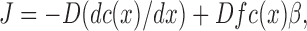
A highly favored theory of passive permeability through lipid bilayers and biomembranes uses the solubility- diffusion (SD) model. This supposes that, for the purpose of understanding permeability P, the bilayer can be modeled as a single layer of hydrocarbon of thickness dC. This leads directly to the well-known formula,
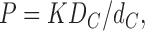 |
(1) |
where K is the partition coefficient of the solute into the hydrocarbon core of the lipid bilayer and DC is the coefficient of diffusion of the solute in the same environment. For small solutes, DC is often (but not always, see Lieb and Stein, 1986) assumed to be weakly dependent upon solute. The strong dependence of P, varying over nearly six orders of magnitude for different solutes for a given lipid bilayer (often egg lecithin), is interpreted as the dependence of K on the solute (Overton's rule). This conclusion is reinforced by the fact that the measured partition coefficients of solutes into bulk hydrocarbon correlate fairly well with permeabilities measured over the same six orders of magnitude (Walter and Gutknecht, 1986; Finkelstein, 1987). This is a major result that any theory must account for. Nevertheless, the fact that the single layer SD theory easily accommodates Overton's rule does not prove that it is the correct model. One concern about the SD theory is that the value of dC obtained from calculating KDC/P exceeds 10 nm for egg lecithin bilayers (Finkelstein, 1987), but the structural thickness of the hydrocarbon core for that lipid bilayer is only 2.7 nm (Nagle and Tristram-Nagle, 2000). The theory in this paper removes this discrepancy.
Another concern with the single layer SD theory regards how to incorporate the dependence of P for a given solute with the area per lipid A for different bilayers. It may be noted first that correlation with A is different than correlation with inverse thickness 1/dC because, even though the product AdC = VC is the volume of the hydrocarbon region, VC is considerably different for lipids with different numbers of carbons in the hydrocarbon chains. Indeed, there is no apparent experimental correlation of the water permeability with dC whereas there is a strong, though not perfect, correlation with A (Mathai et al., 2007). The more relevant structural quantity for discussing the SD theory is the volume per methylene group VCH2 in the hydrocarbon core. The partition coefficient K should increase monotonically with VCH2, as in the “free volume” theory, so VCH2 should be the first order structural quantity to correlate with K. If there were a strong correlation of VCH2 with A, then the A dependence of P could be easily understood as a K dependence within the single layer SD theory. Contrarily, all the lipid bilayers employed in the recent experimental study of water permeability have essentially the same value of VCH2. It may be emphasized that the structural values of VCH2 were obtained from straightforward measurements of the total lipid volume that are highly accurate (Nagle and Tristram-Nagle, 2000; Koenig and Gawrisch, 2005; Greenwood et al., 2006; Heerklotz and Tsamaloukas, 2006). The largest uncertainty was how much to subtract for the volume of the headgroup, but that number should be the same for all phosphatidylcholine lipids in their fully hydrated bilayers, so any discrepancy only changes VCH2 by essentially the same amount for all bilayers. This volumetric result precludes a simple reconciliation of the single layer SD theory with experiment, although a more complex reconciliation based on a lattice model has been proposed (DeYoung and Dill, 1990; Xiang and Anderson, 1995).
This paper therefore goes beyond the single layer SD theory and considers three layer theories such as have been considered by Zwolinski et al. (1949) and Diamond and Katz (1974). The main new idea is that the area dependence is quite naturally included in the interfacial headgroup layers rather than in the fluid hydrocarbon core layer. This theory will be implemented with close comparison to recent water permeability measurements that were made on five pure lipid bilayers, all with the same phosphatidylcholine headgroup and all at the same temperature and all with structures recently determined by the same high resolution X-ray method for fully hydrated lipid bilayers.
THEORY AND RESULTS
I. Three Layer Theory
Before deriving detailed equations from mathematical models, let us develop the major ideas in a phenomenological and intuitive manner. The underlying theory assumes three layers, an inner hydrocarbon core, as in the single layer SD theory, and two interfacial headgroup layers. Let us define the permeabilities through each part separately. Let PC be the permeability that would apply just within the hydrocarbon core and let PH be the permeability through the interfacial region and including, importantly, transfer into the hydrocarbon core. Then, as is well known (Zwolinski et al., 1949; Diamond and Katz, 1974) and as will be shown in detail in the following two subsections, the permeability P of the three layer composite model is given by
 |
(2) |
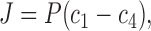
which is just the formula for addition of resistances in series where each of the three separate resistances is proportional to its inverse permeability. A recent experimental study suggested that the headgroup regions and the hydrocarbon region each offer independent and additive resistance to permeation (Krylov et al., 2001).
The most important aspect of our model is the functional form for PH. As suggested by Fig. 1, we suppose that the headgroups sterically block the entrance of water into the hydrocarbon region. We therefore propose a structural factor of (A − A0)/A in PH to account for the fraction of the total area A that is not blocked. The parameter A0 is the area at which the headgroups are packed so tightly that the permeability becomes negligible. Xiang and Anderson (1997) have measured the permeability of acetic acid in the gel phase of DPPC to be 482 times less than in the fluid phase, so a first approximation for A0 is the area of the gel phase. The theory will not attempt to account for gel phase permeability, which appears to be qualitatively different from fluid phase permeability (Xiang et al., 1998). For phosphatidylcholine lipids the gel phase area is ∼48 Å2 and the chains are tilted (Tristram-Nagle et al., 2002). As pointed out by McIntosh (1980), tilting shows that the phosphatidylcholine (PC) headgroups are tightly jammed together in the gel phase. Our permeability model essentially assumes that the headgroups comprise a partial barrier for entry of water into the hydrocarbon region, and the effect of this barrier is naturally proportional to the fractional “free” area (A − A0)/A. This is the single most important feature in our model that will account for the major area dependence found by Mathai et al. (2007).
Figure 1.

Schematic drawing showing three lipids in the top monolayer of a bilayer. The horizontal yellow strips indicate the area A − A 0 accessible for passage of solute through the interfacial headgroup layer and into the hydrocarbon core. The shape of the heads provides a rough approximation to the distribution of water in the headgroup region obtained by simulations (Klauda et al., 2006). We note that our definition of headgroup includes not only the phosphatidylcholines, but also the glycerol and carbonyls. As discussed in the text, the interfacial headgroup region might also include the ends of the hydrocarbon chains where chain packing is tightest and the hydrocarbon core would then be smaller than dC obtained from structural studies.
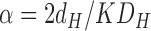
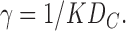
The second part of our model assumes that the hydrocarbon core, by itself, has a permeability PC =KDC/dC, given by the simple SD model for the hydrocarbon core. In this simplest model that we will first consider, the only parameter that will vary between different lipid bilayers is the structural parameter dC, the thickness of the hydrocarbon core. Of course, it might be considered that the effective hydrocarbon core thickness for permeability could be smaller than dC due to tight packing of the first few methylene groups in the hydrocarbon chains (Subczynski et al., 1994; Xiang et al., 1998). One might also suppose that a larger fraction of “free volume,” (V − V0)/V, would increase the space available for water and thereby increase the partition coefficient K. Larger fraction of free volume would also allow for more dynamical motion that would increase the intrinsic coefficient of diffusion DC. However, the volume per methylene is nearly constant for all the fluid phase lipids studied, so such a factor would make no difference between the different lipids we studied.
Therefore, this theory quantitatively predicts that, for pure lipid bilayers, the dependence of P on structural parameters is given by
 |
(3) |
At this point the linear factors α and γ are just fitting parameters that are assumed only to be independent of the structural quantities A, A 0, and dC whose postulated dependencies are explicitly displayed in Eq. 3. Of course, α and γ must be affected by K and by the coefficients of diffusion that may be different in different parts of the bilayer, as will be seen in the following two sections. In first approximation, α and γ will be assumed to be the same for all fully fluid phase lipid bilayers. Fitting these formulae to permeability data for five lipid bilayers with different structural parameters therefore determines α and γ from which the individual permeabilities PH and PC are determined for each of the bilayers.
The first question to investigate is whether both terms on the right hand side of Eq. 3 are significant. It has already been shown (Mathai et al., 2007) that setting α = 0, which is just the single layer SD model, is not adequate because there is a poor correlation of P with 1/dC. The other extreme is to set γ = 0, which corresponds to the hydrocarbon core permeability PC being much greater than the interfacial permeability PH. The open squares in Fig. 2 show that this first term that involves the area A already gives fairly good theoretical values; this reflects the point made by Mathai et al. (2007) that the best correlation of permeability is with A. However, when γ is set to 0, the predicted permeability for the thickest bilayer diC22:1 is too large and the predicted permeability for the thinnest bilayer DLPC is too small. This discrepancy can clearly be alleviated by inclusion of the second term. The red circles in Fig. 2 show the best fit of the theory using Eq. 3. Inclusion of the second term does indeed alleviate the aforementioned discrepancy. The legend to Fig. 2 also shows that the values of the parameter A0 that are given by the best fits are consistent with negligible permeability of the gel phase which has an area 48 Å2 for PC bilayers. The somewhat larger values of A 0 in the legend in Fig. 2 can be justified as accounting for the steric area of a water molecule. Another way that A 0 could be increased for water transport is that “ethanol may block water diffusion pathways by occupying points of water entry into bilayers at the interface” (Huster et al., 1997).
Figure 2.

The plot of theoretical versus experimental permeability for different lipids should ideally fall on the diagonal magenta line. For the open squares, PC was assumed to be infinite. The red circles show the best fit to Eq. 3 and the green triangles show the best fit when the hydrocarbon thickness is reduced by δ = 15 Å. The fitted values of A 0 are shown in the figure legend. The lipids all have phosphatidylcholine (PC) headgroups with two acylated hydrocarbon chains. DMPC and DLPC have saturated chains with 14 and 12 carbons, respectively. DOPC and diC22:1PC have monounsaturated chains with 18 and 22 carbons, respectively. POPC has a palmitic acid chain with 16 carbons in the sn-1 position and a monounsaturated oleoyl chain in the sn-2 position. The experimental permeabilities at 30°C are from Mathai et al. (2007).
Motivated by simulations (Marrink and Berendsen, 1994, 1996) and also by an electron spin resonance (ESR) result (Subczynski et al., 1994) that the hydrophobicity barrier is narrower than dC, we have also investigated a variation of Eq. 3 that models an effective hydrocarbon thickness for permeability by replacing the factor dC in the second term by a factor (dC − δ). The green triangles in Fig. 2 show that the fit is slightly improved when δ = 15 Å and the fit continues to improve as δ increases to 76 Å. However, the physical absurdity of this last result, namely, that the effective hydrocarbon thickness (dC − δ) becomes strongly negative, suggests that adding the fourth fitting parameter δ is not warranted by the data. Indeed, artificially reducing P just for DOPC by 10%, which is close to estimated experimental uncertainties, yields a value of δ close to zero.
Fig. 3 compares the partial permeabilities PH/2 (which includes both interfaces) and PC for the hydrocarbon core for the last two combinations of the parameters shown in Fig. 2. Of course, the ratio PC/PH varies with different lipids due to their different structural properties. The ratio PC/PH also depends upon the choice of effective thickness dC − δ. For both values of δ shown in Fig. 3, PH/2 is smaller than PC, so passage through the headgroup regions is predicted to be the slower process. Nevertheless, 2PC/PH is less than 10 for the thinnest DLPC bilayer and is less than 3 for the thickest diC22:1 bilayer, so the hydrocarbon core permeability plays a role, even though it is secondary to the role played by the headgroup regions.
Figure 3.

The filled symbols show the model values of PH/2 for the permeability of both headgroups and the open symbols show the theoretical values of the hydrocarbon core permeability PC versus the measured P for two parameter choices from Fig. 2. The parameter δ in the legend gives an effective thickness of the core region for different bilayers as dC − δ where dC is the structurally determined thickness that includes the aliphatic chains but not the carbonyls.
II. Two Detailed Models
The preceding section did not address the very important question regarding the role played by the partition coefficient K that is crucial in order for a theory to obey Overton's rule. This section analyzes two mathematical models that answer this question. The two models also predict values for the two linear parameters α and γ in Eq. 3 and this could, in principle, reduce the number of free parameters for fitting data. However, it is important to consider both models because the predicted formula for γ is different. The difference shows that this result of mathematical modeling is not robust, so this comparison prevents the drawing of unwarranted numerical conclusions.
For both mathematical models we will refer to Fig. 4 for the free energy landscape which is the local (noncratic) part of the chemical potential. The free energy of water is assumed to be high and constant in the hydrocarbon core and low in the water. These two regions are separated by the interfacial headgroup regions, which are generally quite complicated. For simplicity, linear forms for the free energy will be assumed. It may be noted that this free energy landscape is qualitatively similar to the hydrophobicity landscapes obtained from spin labeling experiments (Subczynski et al., 1994) and from simulations (Fig.6 of Marrink and Berendsen,1994).
Figure 4.

The free energy landscape for the two models of water permeability considered in this paper is shown in black. For the chemical kinetics model there are four states. States 1 and 4 are at the bulk water boundaries and states 2 and 3 are at the hydrocarbon core boundaries. For the Nernst-Planck model the position x along the perpendicular to the bilayer is a continuous variable.
A: Chemical Kinetics Model.
As advocated long ago by Zwolinski et al. (1949), one may consider a chemical kinetics description of transport and permeability. The simplest mathematical way to describe the physical model shown in Fig. 1 employs four states as shown in Fig. 4. The bulk water phases are represented by states 1 and 4 with concentrations c1 and c4, respectively. The hydrocarbon core is represented by states 2 and 3 with concentrations c2 and c3, respectively. The physical locations of states 2 and 3 are just within the ends of the hydrocarbon core closest to the bulk water states 1 and 4, respectively. The distance between states 2 and 3 is the thickness dC of the hydrocarbon region. The distance between states 1 and 2 (and between states 3 and 4) is the thickness dH of the interfacial headgroup region. The kinetics of water or other solute flow through the membrane are given by the first order kinetics scheme
 |
(4) |
where the forward rate constants between the states can be written k 12, k 23, and k 34, and the backward rate constants are k 21, k 32, and k 43 as shown in Fig. 4. The ratios of backward and forward rate constants are given by equilibrium free energy considerations. For symmetric lipid bilayers
 |
(5) |
where K = exp(−βΔF) is the partition coefficient for water in the hydrocarbon core. It will be convenient to use the simplified notation,
 |
(6) |
In steady state, all concentrations ci are constant in time. The net forward currents between pairs of contiguous states are given by
 |
(7a) |
 |
(7b) |
 |
(7c) |
In steady state, J 12 = J 23 = J 34 = J. Addition of J 12 and J 34 followed by elimination of c2 − c3 using Eq. 7b then gives
 |
(8) |
with
 |
(9) |
Correspondence with Eq. 2 in the text follows by identifying the hydrocarbon core permeability PC = dCkCK and the headgroup permeability PH = dHkHK. Of course, PC is usually written as KDC/dC and this identifies the coefficient of diffusion in the hydrocarbon regions as DC = dC 2 kC, which is the usual formula from random walk theory that gives the coefficient of diffusion as the hopping distance squared divided by hopping time. We next recognize that kH should contain the obstruction factor (A − A 0)/A, which we wish to display explicitly. The local coefficient of diffusion DH within the unobstructed part of the headgroup region, that should be comparable numerically to DC, should not contain an area- dependent factor. It is then given as DH = dH 2 kHA/(A − A0) because kH contains the factor (A − A 0)/A. We therefore have
 |
(10) |
There are two differences between the preceding kinetic modeling and that of Zwolinski et al. (1949). The first is unimportant. They included m − 1 intermediate states in the hydrocarbon region between our states 2 and 3, but as they showed in their Eq. 33, if the additional rate constants are all equal, corresponding to a homogeneous region, and each is scaled by the appropriate multiple of our kC, there is no difference in the final equation for the permeability. The second difference is quite important. Zwolinski et al. (1949) supposed a large free energy barrier to entry of water into the hydrocarbon region in addition to the increase in free energy |ΔF| shown in Fig. 4. In their presentation they did not display the factor of K that must be present even when there is the extra barrier they assumed. In our presentation we have not included any extra free energy barrier. This means that our kH = k 21 = k 34 models transition over negligible barriers into states with considerably lower free energies, so kH should not depend upon K. In the Eyring absolute rate theory (Glasstone et al., 1941) when there is no barrier, kH = kT/h, where h is Planck's constant, kT is thermal energy, and the entire K dependence resides in the rate constants k 12 = k 43 = KkH. Up to this point, our free energy profile across the bilayer has the shape of a mesa with a high flat plateau in the hydrocarbon region with steeply sloping sides into the low plains for the bulk water (Fig. 4). Our innovation in Section I is that, rather than imposing an extra free energy barrier, we impose a geometric obstruction factor on PH, given in Eqs. 3 and 10, that impedes diffusion through a fraction of the bilayer area. This factor may be thought of as a high picket fence on the mesa slope where the pickets represent the headgroup obstructions schematically shown in Fig. 1.
The most serious objection to the model as developed by Zwolinski et al. (1949) comes from reconciling it to Overton's rule. To effect such a reconciliation following their discussion of their Eq. 34, one would have to conclude that PC had to be the rate-limiting step for permeability, as they did on their page 1444. In contrast, our presentation has a factor of K in both PH and PC, and therefore in P, so it satisfies Overton's rule without forcing PC to be rate limiting. Furthermore, it allows a strong area dependence by making solute entry into the hydrocarbon core (up a mesa slope) slower than diffusion through the hydrocarbon core (across a flat mesa).
It may also be noted that Dix et al. (1978) discussed a three layer model in the mathematical framework of Zwolinski et al. (1949). However, they ended their paper with the opposite conclusion, namely, that the rate limiting step was the interfacial resistance and that 2/PH was higher by several orders of magnitude than diffusional resistance 1/PC within the hydrocarbon core. While closer to our conclusion, our Fig. 3 has the ratio within a factor of 10 for fluid phase lipid bilayers. The conclusion of Dix et al. (1978) was based on residency times of water of 100 ns in the membrane. However, it is well known that PC lipid headgroups bind at least one or two water molecules so tightly that they are difficult to remove even by extensive drying (Jendrasiak and Hasty, 1974). We suggest that these strongly bound waters may account for the long residency. To include this in a kinetic model, a state 2b would be added to the left headgroup region that would have a maximum capacity of a few water molecules per lipid and would have very low free energies. State 2b would not be on the linear pathway shown in Fig. 4. Rather, it could be on an alternative branched pathway between states 1 and 2 or it could just be a dead end side path connected only to state 1 or to state 2. As such, it, and its symmetrically equivalent 5b state, would hardly perturb the previous analysis while providing an explanation for long residency times for water molecules in a nonbulk water environment.
This chemical kinetics model makes specific predictions about the two linear parameters in the general theory in Section II. Comparing Eq. 10 with Eq. 3 and the two components PH and PC defined in Eq. 2 gives
 |
(11a) |
 |
(11b) |
Assuming that DC = 2 × 10⁻⁵ cm2/s, Eq. 11b gives K = 5.4 × 10⁻⁴ from the value of γ for the δ = 0 case in Fig. 2 and K = 4.3 × 10⁻⁴ for the δ = 15 Å case. For comparison, the partition coefficient for water in hexadecane is 4.2 × 10⁻⁵ (Walter and Gutknecht, 1986). Then, if we also assume that DH = 2 × 10⁻⁵ cm2/s, Eq. 11a gives the thickness of the headgroup region to be dH = 6.1 Å for either δ = 0 or δ = 15 Å. These are quite reasonable values of K and dH that could be further tuned by modest changes in DH and DC. For example, if we arbitrarily set DC = 10−5 cm2/s and DH = 1.5 × 10⁻⁵ cm2/s, then K ∼ 0.001 and dH = 9.3 Å, which is close to the thickness of the interfacial headgroup region (Nagle and Tristram-Nagle, 2000).
B: Continuum Model.
As a mathematical model, the chemical kinetics model in the previous subsection is rather primitive because the interfacial headgroup region is represented only by one reaction pathway involving only two states, one at each edge of the region. One can ask what the effect would be to have additional states on a linear kinetics pathway within the headgroup region, and the answer is that the final equations change. Rather than adding a few more states, it is more efficient to proceed to the opposite extreme that consists of an infinite number of states; this is the continuum model.
The continuum model is treated by the Nernst-Planck extension of Fick's law for diffusion. Let x be the position perpendicular to the bilayer and let xi be the particular values for the positions labeled i = 1,2,3,4 in Fig. 4, so the headgroup thickness dH = x2 − x1 = x4 − x3 and the hydrocarbon core thickness dC = x3 − x2. Let the free energy difference F(x2) − F(x1) be ΔF and the magnitude of the corresponding force be f = ΔF/dH, noting that f is negative when x 1 < x < x 2. Let c(x) be the concentration of solute and β be the inverse thermal energy 1/kT. Then, for steady state the solute current J is constant as a function of x and is given by the Nernst-Planck equation
 |
(12) |
where D is the coefficient of diffusion. It has been emphasized that D should be a nonconstant function of x (Diamond and Katz, 1974; Marrink and Berendsen, 1994), but to keep the model reasonably simple and calculable, we will assume a constant DC in the hydrocarbon chain region x 2 < x < x 3 where f = 0. In the headgroup regions, x 1 < x < x 2 and x 3 < x < x 4, it is convenient to factor D into the headgroup obstruction factor (A − A 0)/A and a coefficient of diffusion DH in the unobstructed part of the region, with a value of DH that is comparable to DC.
To obtain the permeability, c(x) is first noted to have the following forms in the three separate regions
 |
(13a) |
 |
(13b) |
 |
(13c) |
where b = (JdH/βΔFDH)(A/(A − A 0)). The parameters a1 and a4 are related to the known concentration differences in the bulk phase by
 |
(14a) |
and also to
 |
(14b) |
Elimination of (a1 − a4) then gives
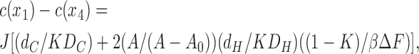 |
(15) |
where K = exp(−βΔF) is the partition coefficient. The factor in square brackets is just 1/P by the definition of permeability and the inverses of the two individual terms therein can be identified as
 |
and
 |
(16) |
The result in Eq. 16 is identical to Eq. 10 for the chemical kinetics model except for the final factor (−ln(K)/(1 − K)) in PH. This factor depends only weakly on K, varying by only about one order of magnitude as K varies by five orders of magnitude for hydrophilic solutes with K < 0.1, so the basic Overton rule dependence of P on K continues to hold.
We next follow the discussion in the last paragraph of the previous subsection. Again, assuming that DC = 2 × 10⁻⁵ cm2/s, PC in Eq. 16 gives K = 5.4 × 10⁻⁴ from the value of γ for the δ = 0 case in Fig. 2. But if we also assume that DH = 2 × 10⁻⁵ cm2/s, then Eq. 16 gives the thickness of the headgroup region to be dH = 46 Å, which is clearly an unphysically large value. However, setting DH = 0.4 × 10⁻⁵ cm2/s obtains a structurally acceptable value of dH = 9 Å. It may be noted that the simulation of Marrink and Berendsen (1994) gives a smaller coefficient of diffusion in the headgroup region than in the hydrocarbon core region.
DISCUSSION
The general phenomenological theory presented in Section I was motivated by the correlation of recently measured water permeability (Mathai et al., 2007) with the structure of lipid bilayers. At the core of this theory is a free area factor (A − A 0)/A, introduced in Eqs. 3, 10, and 16, that is open for permeation. Free area and free volume concepts have been criticized when the free quantities are much smaller than molecular sizes (Edholm and Nagle, 2005). However, the free area concept gains traction when the quantized open area is larger than the area of a water molecule, as it is for typical water pores. This is also the case for the quantity A − A 0, which is the open space locally available in our theory and which is not much smaller than water molecules.
While quite general, it is important that this essentially postulated theory be consistent with more specific, microscopic models and calculations. Section II shows that there are at least two different microscopic models from which the phenomenological theory is derivable. The phenomenological theory in Eq. 3 also did not explicitly include any role for the partition coefficient K or coefficients of diffusion, but this is provided by the detailed models. Both the chemical kinetics model (Eq. 10) and the continuum Nernst-Planck model (Eq. 16) have a linear K factor in both the headgroup permeability PH and in the chain permeability PC. In contrast to the coefficients of diffusion, which can be different in the core and headgroup regions, there is only one partition coefficient given in Eq. 5 by the Boltzmann factor K = exp(−βΔF) for the free energy difference ΔF of the solute in the hydrocarbon core versus water. This is an important result because it shows that a three layer theory is consistent with Overton's rule. The three layer theory also removes the discrepancy that the hydrocarbon core thickness is too large in the single layer solubility-diffusion theory. Fig. 3 shows that PC can be quite large as is required in order to have realistic values of dC because the experimental permeability is primarily determined in Eq. 2 by the smaller PH, which provides the greater resistance.
The theoretical result for the continuum model (Eq. 16) is different from the chemical kinetics model (Eq. 10) by having a weakly varying logarithmic K factor in the headgroup permeability PH. The last paragraphs of the two subsections in Section II show that either model leads to reasonable results for the thickness of the headgroup region dH provided that the unknown coefficients of diffusion DH and DC are chosen appropriately. However, because of the lnK factor in the continuum model, the ratio DH/DC is different for the two models. The smaller value of DH/DC required for the continuum model is consistent with the presence of local free energy minima within the heterogeneous headgroup region that could trap the solute for periods of time long compared with free diffusion in the more homogeneous hydrocarbon chain environment as suggested by Marrink and Berendsen (1994). While quite plausible, our results may not warrant such a firm conclusion. We assumed in the continuum model that the free energy profile is linear in the headgroup region (Eq. 13), but this leads to an exponential water concentration profile, whereas computer simulations suggest a more nearly linear water profile, as indicated in Fig. 1. Any continuum model requires detailed assumptions about the free energy profile that can be quite complicated and uncertain and obscure the main ideas, so we have chosen not to pursue variations of the continuum model. The chemical kinetics model avoids such complications by incorporating all the details of the headgroup region into a single rate constant, which has the merit of simplicity. Chemical kinetics models also allow for easy variations in the free energy landscape to treat detailed aspects of other solutes, as shown in the online supplemental materials (available at http://www.jgp.org/cgi/content/full/jgp.200709849/DC1).
All the fitting to water permeability data in this paper assumed that the partition coefficient K is the same in the five lipid bilayers. One might suppose that K for water would be larger for lipids with more polarizable unsaturated double bonds, as appears to be the case for polyunsaturated lipids (Huster et al., 1997; Olbrich et al., 2000). This would account for the theoretical permeability being too low for DOPC in Fig. 2 but it would make the fit worse for diC22:1PC. Also, electron spin resonance (ESR) measurements suggest that DOPC is more, rather than less, hydrophobic than lipids with saturated chains (Subczynski et al., 1994), so we have chosen not to allow variations in K, which is consistent with all the lipids having the same density of packing, i.e., the same VCH2.
The theory as presented uses average structural quantities, such as the average area A of the headgroups. Of course, there are fluctuations in the local A in the fluid phase of bilayers, and the permeability will be transiently enhanced locally when A fluctuates to a larger value. Indeed, it has been suggested that the anomalously large permeability of bilayers to Na+ ions near the main chain melting phase transition is due to the nonlinear effect of greater fluctuations in the local area that must occur when the lateral area modulus KA becomes small near a higher order phase transition (Nagle and Scott, 1978). However, none of the bilayers discussed here were in critical regions near the chain-melting transition temperature and all had values of KA that were substantially the same (Rawicz et al., 2000). The lack of empirical correlation of P with KA (Mathai et al., 2007) suggests that average structural quantities suffice.
The bilayers used in Figs. 2 and 3 all had the same headgroup. Water permeability data for DLPE and DOPS are also presented by Mathai et al. (2007) and compared with structural data. Of course, different head groups should require different values of A 0 and possibly different values of the coefficient of diffusion DH in the headgroup region, so data from at least two different lipids with the same headgroup are required to obtain both parameters to enable a comparison to the PC lipids. Since we do not have those data, let us assume that DH is the same as for PC lipids. Then, the values of A 0 required to match theory, using Eq. 3, to experiment are A 0 = 51.2 Å2 for DOPS and A 0 = 50.1 Å2 for DLPE. As would be expected, these values are smaller than the A 0 = 53.6 Å2 given in Fig. 2 for the PC headgroups, but they are not as much smaller as would be expected by the gel phase areas that are 41.0 Å2 for DLPE (McIntosh and Simon, 1986) and 40.8 Å2 for DMPS (Petrache et al., 2004), ∼7 Å2 less than the 47–48 Å2 for PC headgroups. However, compared with PC headgroups, PE and PS headgroups have additional hydrogen bonding opportunities that could be modeled either as blocking some of the area available for water permeation (i.e., increasing A 0) or as providing local traps that would reduce DH (Marrink and Berendsen, 1994). Water permeability and structural data for DOPC with 10, 20, and 40% cholesterol were also presented by Mathai et al. (2007). Incorporation of cholesterol into our theory requires additional choices. Cholesterol might additionally obstruct entry of the water into the hydrocarbon region, or it might not, according to the theory of Huang and Feigenson (1999) that the headgroups shield the cholesterol from water. Also, the rigid ring structure of cholesterol might obstruct the diffusion within the hydrocarbon region. With enough cholesterol, the hydrocarbon chains become more ordered, like a gel phase, and less mobile, so DC might become smaller. Furthermore, it has been suggested that K should be reduced by cholesterol (DeYoung and Dill, 1990; Xiang and Anderson, 1997), as seems plausible as the phase becomes liquid ordered instead of fully fluid. These are issues that are difficult to model, and we have chosen not to include cholesterol data in the fits in this paper. However, if we assume that α and γ in Eq. 3 are the same as for fully fluid phase lipids, then the values of A 0 required to match theory and experiment in Fig. 2 are A 0 = 53.1 Å2 for DOPC with 10% cholesterol, A 0 = 55.2 Å2 for DOPC with 20% cholesterol, and A 0 = 58.0 Å2 for DOPC with 40% cholesterol.
While this theory has been motivated by water permeability measurements and while the tests presented use only these data, we suggest that the general theory may apply more generally to other solutes. Two classes of solute are considered in detail in the online supplemental material (http://www.jgp.org/cgi/content/full/jgp.200709849/DC1). The first is solutes, like acetic acid, that have been suggested to have strong binding to the interfacial region of bilayers (Xiang and Anderson, 1995). The second class is hydrophobic solutes whose partition coefficients into oil are greater than unity. We suggest that studies with different solutes concentrate primarily on bilayers with lipids that share the same headgroup and whose structures have been determined. Even with this constraint, one should expect some of the parameters and even the underlying free energy landscapes to be different from Fig. 4, as discussed in the online supplemental material.
Even homogeneous lipid bilayers have more complexity than can readily be included in a simple theory for passive permeability, so perfect agreement with experiment is not a realistic goal. As was emphasized by Diamond and Katz (1974) and mentioned many times since, the most realistic models would include partition coefficients and coefficients of diffusion that would vary continuously through the bilayer. However, an appropriate goal should still be a simple theory that can provide insight while accommodating the most significant permeability data with a reasonably small number of measurable parameters. With more precise structural data on lipid bilayers now available (Mathai et al., 2007), we believe that it is warranted to return to the approach of Zwolinski et al. (1949) and Diamond and Katz (1974) and try to improve the theory beyond the single layer solubility-diffusion model while stopping short of the continuous description with infinitely many parameters. We offer the present three layer theory, which should be tested further experimentally with other solutes and with other lipid bilayers when their structures are determined.
Supplemental Material
Acknowledgments
This research was supported by the National Institutes of Health, grants GM 44976 (J.F. Nagle) and DK43955 (M.L. Zeidel, J.C. Mathai, and S. Tristram-Nagle).
Olaf S. Andersen served as editor.
Abbreviations used in this paper: PC, phosphatidylcholine; SD, solubility-diffusion.
References
- DeYoung, L.R., and K.A. Dill. 1990. Partitioning of nonpolar solutes into bilayers and amorphous n-alkanes. J. Physiol. Chem. 96:801–809. [Google Scholar]
- Diamond, J.M., and Y. Katz. 1974. Interpretation of nonelectrolyte partition coefficients between dimyristoyl lecithin and water. J. Membr. Biol. 17:121–154. [DOI] [PubMed] [Google Scholar]
- Dix, J.A., D. Kivelson, and J.M. Diamond. 1978. Molecular motion of small nonelectrolyte molecules in lecithin bilayers. J. Membr. Biol. 40:315–342. [DOI] [PubMed] [Google Scholar]
- Edholm, O., and J.F. Nagle. 2005. Areas of molecules in membranes consisting of mixtures. Biophys. J. 89:1827–1832. [DOI] [PMC free article] [PubMed] [Google Scholar]
- Finkelstein, A. 1987. Water Movement Through Lipid Bilayers, Pores, and Plasma Membranes: Theory and Reality. Wiley Interscience, New York. 228 pp.
- Glasstone, S., K.J. Laidler, and H. Eyring. 1941. The theory of rate processes; the kinetics of chemical reactions, viscosity, diffusion and electrochemical phenomena. First edition. McGraw-Hill Book Company Inc., New York. 611 pp.
- Greenwood, A.I., S. Tristram-Nagle, and J.F. Nagle. 2006. Partial molecular volumes of lipids and cholesterol. Chem Phys. Lipids. 143:1–10. [DOI] [PMC free article] [PubMed] [Google Scholar]
- Heerklotz, H., and A. Tsamaloukas. 2006. Gradual change or phase transition: characterizing fluid lipid-cholesterol membranes on the basis of thermal volume changes. Biophys. J. 91:600–607. [DOI] [PMC free article] [PubMed] [Google Scholar]
- Huang, J., and G.W. Feigenson. 1999. A microscopic interaction model of maximum solubility of cholesterol in lipid bilayers. Biophys. J. 76:2142–2157. [DOI] [PMC free article] [PubMed] [Google Scholar]
- Huster, D., A.J. Jin, K. Arnold, and K. Gawrisch. 1997. Water permeability of polyunsaturated lipid membranes measured by 17O NMR. Biophys. J. 73:855–864. [DOI] [PMC free article] [PubMed] [Google Scholar]
- Jendrasiak, G.L., and J.H. Hasty. 1974. The hydration of phospholipids. Biochim. Biophys. Acta. 337:79–91. [DOI] [PubMed] [Google Scholar]
- Klauda, J.B., N. Kucerka, B.R. Brooks, R.W. Pastor, and J.F. Nagle. 2006. Simulation-based methods for interpreting x-ray data from lipid bilayers. Biophys. J. 90:2796–2807. [DOI] [PMC free article] [PubMed] [Google Scholar]
- Koenig, B.W., and K. Gawrisch. 2005. Specific volumes of unsaturated phosphatidylcholines in the liquid crystalline lamellar phase. Biochim. Biophys. Acta. 1715:65–70. [DOI] [PubMed] [Google Scholar]
- Krylov, A.V., P. Pohl, M.L. Zeidel, and W.G. Hill. 2001. Water permeability of asymmetric planar lipid bilayers: leaflets of different composition offer independent and additive resistances to permeation. J. Gen. Physiol. 118:333–340. [DOI] [PMC free article] [PubMed] [Google Scholar]
- Lieb, W.R., and W.D. Stein. 1986. Transport and Diffusion Across Cell Membranes. Academic Press Inc., Orlando, FL. 685 pp.
- Marrink, S.J., and H.J.C. Berendsen. 1994. Simulation of water transport through a lipid membrane. J. Physiol. Chem. 98:4115–4168. [Google Scholar]
- Marrink, S.J., and H.J.C. Berendsen. 1996. Permeation process of small molecules across lipid membranes studied by molecular dynamics simulations. J. Physiol. Chem. 100:16729–16738. [Google Scholar]
- Mathai, J.C., S. Tristram-Nagle, J.F. Nagle, and M.L. Zeidel. 2007. Structural Determinants of Water Permeability Through The Lipid Membrane. J. Gen. Physiol. 131:69–76. [DOI] [PMC free article] [PubMed] [Google Scholar]
- McIntosh, T.J. 1980. Differences in hydrocarbon chain tilt between hydrated phosphatidylethanolamine and phosphatidylcholine bilayers. A molecular packing model. Biophys. J. 29:237–245. [DOI] [PMC free article] [PubMed] [Google Scholar]
- McIntosh, T.J., and S.A. Simon. 1986. Area per molecule and distribution of water in fully hydrated dilauroylphosphatidylethanolamine bilayers. Biochemistry. 25:4948–4952. [DOI] [PubMed] [Google Scholar]
- Nagle, J.F., and H.L. Scott Jr. 1978. Lateral compressibility of lipid mono- and bilayers. Theory of membrane permeability. Biochim. Biophys. Acta. 513:236–243. [DOI] [PubMed] [Google Scholar]
- Nagle, J.F., and S. Tristram-Nagle. 2000. Structure of lipid bilayers. Biochim. Biophys. Acta. 1469:159–195. [DOI] [PMC free article] [PubMed] [Google Scholar]
- Olbrich, K., W. Rawicz, D. Needham, and E. Evans. 2000. Water permeability and mechanical strength of polyunsaturated lipid bilayers. Biophys. J. 79:321–327. [DOI] [PMC free article] [PubMed] [Google Scholar]
- Petrache, H.I., S. Tristram-Nagle, K. Gawrisch, D. Harries, V.A. Parsegian, and J.F. Nagle. 2004. Structure and fluctuations of charged phosphatidylserine bilayers in the absence of salt. Biophys. J. 86:1574–1586. [DOI] [PMC free article] [PubMed] [Google Scholar]
- Rawicz, W., K.C. Olbrich, T. McIntosh, D. Needham, and E. Evans. 2000. Effect of chain length and unsaturation on elasticity of lipid bilayers. Biophys. J. 79:328–339. [DOI] [PMC free article] [PubMed] [Google Scholar]
- Subczynski, W.K., A. Wisniewska, J.J. Yin, J.S. Hyde, and A. Kusumi. 1994. Hydrophobic barriers of lipid bilayer membranes formed by reduction of water penetration by alkyl chain unsaturation and cholesterol. Biochemistry. 33:7670–7681. [DOI] [PubMed] [Google Scholar]
- Tristram-Nagle, S., Y. Liu, J. Legleiter, and J.F. Nagle. 2002. Structure of gel phase DMPC determined by X-ray diffraction. Biophys. J. 83:3324–3335. [DOI] [PMC free article] [PubMed] [Google Scholar]
- Walter, A., and J. Gutknecht. 1986. Permeability of small nonelectrolytes through lipid bilayer membranes. J. Membr. Biol. 90:207–217. [DOI] [PubMed] [Google Scholar]
- Xiang, T.X., and B.D. Anderson. 1995. Phospholipid surface density determines the partitioning and permeability of acetic acid in DMPC:cholesterol bilayers. J. Membr. Biol. 148:157–167. [DOI] [PubMed] [Google Scholar]
- Xiang, T.X., and B.D. Anderson. 1997. Permeability of acetic acid across gel and liquid-crystalline lipid bilayers conforms to free-surface-area theory. Biophys. J. 72:223–237. [DOI] [PMC free article] [PubMed] [Google Scholar]
- Xiang, T., Y. Xu, and B.D. Anderson. 1998. The barrier domain for solute permeation varies with lipid bilayer phase structure. J. Membr. Biol. 165:77–90. [DOI] [PubMed] [Google Scholar]
- Zwolinski, B.J., H. Eyring, and C.E. Reese. 1949. Diffusion and membrane permeability. I. J. Phys. Colloid. Chem. 53:1426–1453. [Google Scholar]
Associated Data
This section collects any data citations, data availability statements, or supplementary materials included in this article.