

Abstract
Models of bursting in single cells typically include two subsystems with different time scales. Variations in one or more slow variables switch the system between a silent and a spiking state. We have developed a model for bursting in the pituitary lactotroph that does not include any slow variable. The model incorporates fast, non-inactivating calcium and potassium currents (the spike generating mechanism) as well as the fast, inactivating A-type potassium current (IA). IA is only active briefly at the beginning of a burst, but this brief impulse of IA acts as a burst trigger, injecting the spike trajectory close to an unstable steady state. The spiraling of the trajectory away from the steady state produces a period of low amplitude spiking typical of lactotrophs. Increasing the conductance of A-type potassium current brings the trajectory closer to the unstable steady state, increasing burst duration. However, this also increases interburst interval and for larger conductance values all activity stops. To our knowledge, this is the first example of a physiologically based, single-compartmental model of bursting with no slow subsystem.
Introduction
Bursting is a common pattern of electrical activity in excitable cells. It is characterized by brief periods of fast spiking (the active phase) and quiescent periods (the silent phase). The bursting pattern is usually associated with a higher level of hormone or neurotransmitter secretion (Cazalis et al., 1985; Nunemaker et al., 2003; Stojilkovic et al., 2005) when compared with continous spiking patterns. There is evidence that bursting may have important roles in signaling in neurons (Gabbiani et al., 1996; Lisman, 1997).
Numerous mathematical models of bursting in neural and endocrine cells have been developed (Coombes and Bressloff, 2005). Typically, the model can be split into fast and slow subsystems, and bursting oscillations are driven by slow activity-dependent oscillations in the slow variables. The fast subsystem is usually bistable with a stable steady state coexisting with a stable periodic (spiking) solution. One or more slow variables then switch the system between these attractors (Rinzel, 1985; Rinzel, 1987). The duration of the burst depends on the dynamics of the slow variable(s).
In a recently developed mathematical model of the pituitary lactotroph, we demonstrated that adding a fast A-type K+ current can increase secretion (Tabak et al., in press). This is in spite of the fact that IA is a hyperpolarizing current, and would typically be expected to reduce secretion by hyperpolarizing the membrane. The stimulatory action occurs by converting the spiking pattern to bursting. Surprisingly, we found cases of bursting in which bistability was not present in the fast subsystem. Also, bursting persisted when the only slow variable in the model, the intracellular Ca2+ concentration, was held fixed. Figure 1 illustrates the difference between this type of bursting and “standard” bursting based on bistability and a slow variable. In both panels, slow oscillations of Ca2+ occur in parallel with the slow voltage oscillations. Nevertheless, Ca2+ plays a different role in each case. In Figure 1A, bursting is terminated if intracellular Ca2+ is held constant. This is classic bursting, where the slow changes in Ca2+ are driving the bursts. In contrast, for the case shown in Figure 1B, clamping Ca2+ does not stop the bursts. This indicates that Ca2+ is not driving the bursts but simply follows the bursts. The goal of this work is to analyze the latter type of bursting and contrast its mechanism with the standard bursting mechanisms.
Figure 1.

Bursting in a lactotroph model with different A-type current conductances (Tabak et al., in press). (A) For gA=25 nS bursting is terminated if intracellular Ca2+ is held constant. The bursting mechanism relies on slow variations of Ca2+. (B) For gA=8 nS clamping Ca2+ does not stop the bursts. This indicates an intrinsic bursting mechanism independent of Ca2+.
To facilitate the analysis we removed non-essential elements from the lactotroph model. The slow variable in the original model (Ca2+ concentration) is removed, and the original Ca2+-activated K+ current is treated as a constant conductance current. This results in a simplified model with only three variables, all of which vary on a fast time scale relative to the burst period. We show that bursting can be produced with this model in the absence of a slow variable, and analyze the dynamic mechanism for this novel form of bursting.
Model
The model is a simplification of a recent model for the electrical activity of the pituitary lactotroph (Tabak et al., in press). The simplified model incorporates three voltage-gated currents: a Ca2+ current (ICa), a delayed-rectifier K+ current (IDR) and a fast and transient A-type K+ current (IA). There is also a non-voltage-gated leak current IL. The dynamics of the three variables V (membrane potential), n (activation of IDR) and e (inactivation of IA) are described by:
| (1) |
| (2) |
| (3) |
The ionic currents are given by
| (4) |
| (5) |
| (6) |
| (7) |
and the steady state activation functions have the form
| (8) |
where x represents an activation variable (m, n and a). The inactivation steady state function is
| (9) |
When IA is not present (gA=0) the model has the form of the Morris-Lecar model (Morris and Lecar, 1981).
Parameter values are given in Table 1. Values of the kinetic parameters for ICa were obtained from (Lledo et al., 1990) and the values for IDR and IA are based on (Herrington and Lingle, 1994). Equations were integrated, and bifurcation diagrams were constructed using the software package XPPAUT (Ermentrout, 2002). The fourth-order Runge-Kutta integration method was used, with a time step of 0.5 ms. Reducing the time step had no effect on the simulations.
Table 1.
| Parameter | Value | Definition |
|---|---|---|
| C | 10 pF | Membrane capacitance |
| gCa | 2 nS | Maximal conductance of Ca2+ channels |
| VCa | 50 mV | Reversal potential for Ca2+ |
| vm | −20 mV | Voltage value at midpoint of m∞ |
| sm | 12 mV | Slope parameter of m∞ |
| gDR | 4.4 nS | Maximal conductance of DR K+ channels |
| VK | −75 mV | Reversal potential for K+ |
| vn | −5 mV | Voltage value at midpoint of n∞ |
| sn | 10 mV | Slope parameter of n∞ |
| τn | 43 ms | Time constant of n |
| gA | 0–20 nS | Maximal conductance of A channels |
| va | −20 mV | Voltage value at midpoint of a∞ |
| sa | 10 mV | Slope parameter of a∞ |
| ve | −60 mV | Voltage value at midpoint of e∞ |
| se | 5 mV | Slope parameter of e∞ |
| gL | 0.3 nS | Maximal conductance of leak current |
| τe | 20 ms | Time constant of e |
Results
IA converts spiking into bursting
In our recent model of the pituitary lactotroph we found that adding a small amount of A-type K+ current converts the model cell from a spiker to a burster (Tabak et al., in press). Surprisingly, this bursting could occur independently of the slow Ca2+ dynamics. That is, the burst period was unaffected by changes in the Ca2+ time constant and bursting persisted when the slow Ca2+ variable was clamped (Figure 1B). To investigate this behavior, we have removed all non-essential elements from the model, including the Ca2+ concentration variable. The remaining variables (equations (1–3)) are now all fast relative to the burst period. Figure 2 illustrates the effect of increasing gA from 0 to 13 nS. For gA=0 (Fig. 2A) the model cell is spiking. When gA is increased to 13 nS (Fig. 2B) the spiking is converted into bursting. The duration of the burst, approximately 600 ms, is much larger than the time constants of all model variables (τn=43 ms, τe=20 ms and the membrane time constant is 33 ms).
Figure 2.

IA converts spiking to bursting. (A) For gA=0 nS the model cell is spiking. (B) Increasing the A-type K+ channel conductance to gA=13 nS converts spiking to bursting.
Rush and Rinzel (1995) also obtained a switch to bursting by adding an A current to a spiking model. In their case, though, the inactivation variable of the A current acted as a slow variable, switching the fast subsystem between a high (oscillatory) state and a low stable state. To demonstrate that this is not the case in our model, we plot in Figure 3 the bifurcation diagram of the V – n subsystem with e treated as a parameter. For e = 0, the system has a single unstable steady state surrounded by a stable limit cycle. As e is increased, the steady state becomes stable through a subcritical Hopf bifurcation (HB). The periodic branch born at the Hopf bifurcation emerges as unstable, but gains stability at a saddle node of periodic (SNP) bifurcation. Between the HB and SNP bifurcations there is a region of bistability, with coexisting stable steady state and periodic solutions. However, the burst trajectory (superimposed) does not utilize this bistability region, and indeed does not follow the bifurcation diagram of the V-n subsystem. It is also clear from Fig. 3B that e does not vary much from 0 during most of the active phase and therefore does not terminate the bursts. Together, these observations indicate that the bursting shown in Fig. 2B cannot be described using fast/slow analysis with e as the slow variable.
Figure 3.

(A) Bifurcation diagram of the V – n subsystem with inactivation variable e treated as a parameter (gA = 13 nS). Thick lines represent stable solutions and thin lines represent unstable ones. The maximum and minimum of the periodic solution are shown as upper and lower periodic branches respectively. The projection of the burst trajectory of the full system is superimposed, and does not follow the bifurcation diagram of the V-n subsystem. (B) Magnification of the area at low e. Most of the active phase of the burst occurs near e = 0. HB-Hopf bifurcation, SNP- saddle node of periodic bifurcation.
IA acts as a burst trigger
To investigate the mechanism of burst generation we plot the two potassium currents of the model, IDR and IA, during one full burst cycle. IDR reflects the burst trajectory. IA is near zero during most of the active phase, peaking at the onset of the burst (Fig. 4). Is the entire IA impulse necessary for bursting? To address this question, we blocked IA at different time points during the burst. In Figure 5A we blocked IA (set gA=0) after 80 ms, which is midway along the downstroke of the impulse. As a result, the burst is totally eliminated and only a single large-amplitude spike is produced. Note also that when IA is blocked subsequent bursts do not occur.
Figure 4.

Two K+ currents during one full burst cycle (gA=13 nS). There is an impulse in IA at the beginning of the burst, and IA is near zero during the remainder of the active phase.
Figure 5.

The effect of blocking IA at different time points. (A) IA blocked at 80 ms eliminates the burst, (B) IA blocked at 87 ms reduces the burst to two spikes (C) IA blocked at 90 ms results in a complete burst. Before the block gA = 13 nS.
Thus a nearly complete IA impulse is necessary to induce bursting, but is it sufficient? If we block IA only 7 ms later, at 87 ms (Fig. 5B), then the burst appears but it is short, with only 2 spikes per burst. If IA is blocked at 90 ms (Fig. 5C), when the IA impulse is almost complete, the burst is complete. That is, the burst has the same length as the control burst in Fig. 4. Thus the IA impulse alone is sufficient to induce bursting; IA can be set to zero throughout the remainder of the burst and the burst will proceed. Therefore, the IA impulse acts as a trigger for bursting.
How does the IA impulse trigger the burst? To address this question we view the burst trajectory in the V-n-IA space. Figures 6A–6C correspond to the IA current profiles of Figures 5A–5C. Figure 6D shows the trajectory without any block of IA (current profile in Fig. 4).
Figure 6.
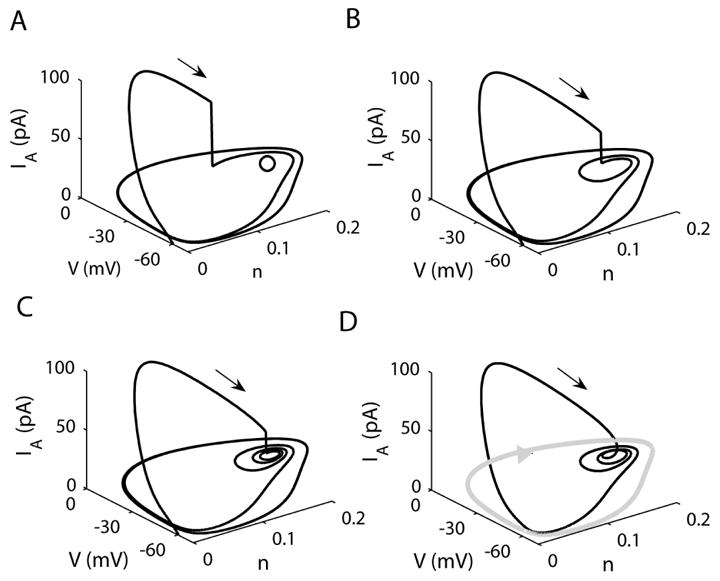
The effect of IA block shown in the V-n-IA space. (A) IA blocked at 80 ms, the open circle in the V-n plane represents the unstable steady state, (B) IA blocked at 87 ms, (C) IA blocked at 90 ms, (D) Trajectory with unblocked IA (gA = 13 nS). The grey curve represents the continuous spiking limit cycle (gA = 0).
When gA=0 the system spikes and the spiking trajectory is in the V-n plane, surrounding an unstable steady state. This spiking trajectory is shown in grey in Fig. 6D. When gA=13 nS (Fig. 6A), the trajectory leaves the V-n plane during the IA impulse. Blocking IA at 80 ms returns the trajectory to the V-n plane, where it approaches the spiking limit cycle around the unstable steady state (open circle).
When IA is blocked later, at 87 ms, the trajectory re-enters the V-n plane closer to the unstable steady state, and spirals around it twice before approaching the spiking limit cycle (Fig. 6B). Each spiral is a low amplitude electrical impulse during the active phase of the burst (Fig. 5B). If IA is blocked later, at 90 ms, the trajectory re-enters even closer to the unstable steady state (Fig. 6C). As a result, more spirals occur before the trajectory moves out towards the spiking limit cycle. This produces a burst with more low-amplitude spikes (Fig. 5C). When IA is not blocked, the trajectory enters the V-n plane near the unstable steady state at the end of the IA impulse (Fig. 6D). The remainder of the burst takes place in the V-n plane, so IA plays no role after the impulse.
Increase in IA increases burst duration
Not only does the IA impulse trigger the burst, but its magnitude determines the burst length. In Fig. 7 A, gA is increased from 0 to 23 nS in steps. When gA is increased to 3 nS, the spiking pattern switches to a two-spike burst. Another spike is added when gA is increased to 7 nS. Increasing gA to13 nS adds a fourth spike to the burst and so on. There are also more complex spiking patterns between the regular n-spike bursts. We found more complex and chaotic patterns between the 2- and 3-spike bursts, 3- and 4- spike burst, as well as between the 4- and 5-spike patterns (Fig 7 C). Further increase of gA, larger than 20.85 nS, stops all activity.
Figure 7.

(A) Increasing gA increases the number of spikes per burst until activity stops. (B) Bifurcation diagram for the V-e subsystem with n treated as a parameter, for gA = 0 (dotted line), gA = 7 nS (dashed line) and gA = 23 nS (solid line).The n-nullcline is also shown. Open circles represent unstable steady states and the closed circle denotes a stable steady state. (C) Number of spikes per burst as function of gA. The chaotic bursting regions are between the dashed lines.
Figure 7B shows the bifurcation diagram of the V-e subsystem with n treated as a parameter for different values of gA. The n-nullcline is also shown. The lower and upper branches of the z-shaped bifurcation diagram consists of stable equilibria of the V-e subsystem, while equilibria on the middle branch are unstable. For lower values of gA (gA = 0 and gA = 7 nS) there is a single depolarized unstable steady state of the full V-e-n system. Increasing gA stretches the bifurcation diagram so that the lower knee moves to the left. When gA = 23 nS, the lower knee intersects the n-nullcline and two new steady states appear, one of which is stable. The trajectory is now attracted to this lower stable steady state and bursting stops.
To explain how the burst increases in length with an increase in gA, we project the burst trajectory onto the V-n plane. Figure 8A shows the superimposed trajectories with gA=0 and gA=3 nS. The dashed curve is the spiking trajectory when gA=0. The unstable steady state (open circle) is the intersection of the V and n nullclines (dash-dotted curves). When gA is increased to 3 nS (solid curve), the rapidly activating hyperpolarizing current reduces the rise in voltage during the upstroke of the spike (arrow), so the trajectory comes closer to the unstable spiral. Movement around this spiral produces a burst with two spikes. For larger IA (gA=7 nS) the trajectory has a closer approach to the unstable spiral (Fig. 8B), making three turns around it before entering the silent phase of the burst. Thus a larger IA moves the trajectory closer to the unstable spiral, creating a longer active phase of the burst. Note that the number of revolutions around the unstable spiral is highly sensitive to the way that the trajectory approaches the spiral at the beginning of the burst. Thus, chaotic spiking patterns can be produced, as mentioned above.
Figure 8.

Mechanism by which increasing the IA impulse magnitude increases the burst duration. (A) Trajectories projected onto the V-n plane with gA=0 nS (dotted line) and gA=3 nS (solid line). The dash-dotted lines are the V and n nullclines for gA=0. The arrow indicates the beginning of the spike upstroke and the open circle is an unstable steady state (B) The V-n phase plane for gA=3 nS (dotted line) and gA=7 nS (solid line). The increase in gA moves the trajectory closer to the unstable steady state, producing more spikes per burst.
How is the trajectory driven toward an unstable steady state?
The previous results show that by turning on at the beginning of a burst, IA pushes the trajectory toward the unstable-steady state of the V – n subsystem. For larger IA, the trajectory passes closer to that unstable steady state. How can IA bring the trajectory so close to a repellent state? As shown on Fig 3, the steady state of the V – n subsystem becomes stable when e increases above its value at the Hopf bifurcation (~0.015). At the beginning of a burst, before IA is fully inactivated, this stable steady state can behave as an attractor and thus bend the trajectory as shown above, before becoming unstable as e reaches 0.
This is shown on Fig. 9. Although e is not a slow variable, we have slowed it down (τe increased 4-fold to 80 ms) to better demonstrate the effect, as was done by Drover et al. (2004). The figure shows the trajectory of the system projected in the V – n plane. Five points (a to e) along the trajectory at the onset of a burst are represented. They correspond to values of e of 0.5, 0.2, 0.1, 0.05 and 0.02. For each of these points, the corresponding V-nullcline of the V – n subsystem is shown (z-shaped, dashed). The intersection of each V-nullcline and the n-nullcline (dot-dashed curve) is a stable steady state of the V – n subsystem for the corresponding e and a pseudo steady state for the full system. Thus, if e were frozen when the trajectory is at point a, it would be attracted to the stable steady state just above a. However e decreases, so the z-shaped curve moves up and to the right and so does the attracting steady state. The trajectory thus never reaches any of the pseudo steady states, but it is bent while tracking these moving targets. When e is near zero, the steady state becomes unstable, but only weakly so. Thus, the trajectory spirals away, but at a slow rate. A similar situation occurs when e is not slowed down, but then the z-shaped curves move faster, so the trajectory is less affected and does not come as close to the unstable steady state as IA fully inactivates.
Figure 9.

Bending of the trajectory in V – n space for τe= 80 ms. Points a-e correspond to values of e of 0.5, 0.2, 0.1, 0.05 and 0.02. For each of these points the corresponding V-nullcline of the V – n subsystem is represented (dashed z-shaped curve), as is the n-nullcline (dash-dotted). As V increases, e decreases, moving the V-nullcline upwards and to the right. The intersections of the n-nullcline and the V-nullclines corresponding to points a–e are steady states of the V – n subsystem, not of the V – n – e system. Only the intersection for e = 0 defines a steady state of the full system. Inset: time course of membrane potential during one “burst”. Most of the burst period is spent in the active phase where e ≈ 0.
This picture illustrates the fundamental difference between “standard” bursting (i.e. square wave bursting) and the bursting presented here. In standard bursting, a slow variable slowly takes the system to transition points where activity abruptly switches between high (oscillatory) and low (stationary) states. In our model, a fast variable quickly moves the only steady state of the V – n subsystem between a high, unstable position to a series of low, stable positions, thus creating the different phases of the burst.
Finally, this highlights the two characteristics of IA needed to produce this type of bursting. First, IA needs to activate quickly, so that the unstable steady state of the V – n subsystem can become attracting. Second, it needs to inactivate, otherwise the system would remain indefinitely in that steady state.
Discussion
We have shown a new mechanism for bursting in a simplified excitable cell model. In classical bursters, the system can be split into fast and slow subsystems, and bursting oscillations are driven by slow activity-dependent oscillations in the slow variables. The fast subsystem is usually bistable with a stable steady state coexisting with a stable periodic (spiking) solution. One or more slow variables then switch the system between these attractors. Unlike classical bursting, the bursting that we describe is produced without a slow variable. An A-type K+ current converts the spiking pattern to bursting by injecting the trajectory to a location near an unstable spiral. Motion around the spiral creates low-amplitude spikes riding on a voltage plateau, similar to what is observed in pituitary lactotrophs (Oxford and Tse, 1993; Van Goor et al., 2001b), somatotrophs (Van Goor et al., 2001a) corticotrophs (Kuryshev et al., 1996; Kuryshev et al., 1997) and clonal pituitary cells (Adler et al., 1983). IA also plays its traditional role of slowing down the next occurrence of an impulse, contributing to the silent phase duration between the bursts.
The A-type potassium current is widely known to delay spiking or reduce firing frequency (Connor et al., 1977). It has been shown that changes in this current’s conductance and dynamic properties can result in bursting (Rush and Rinzel, 1995). However, in the Rush-Rinzel model the A-current inactivation acts as a slow variable to terminate the burst. This is a “classic” fast-slow system, with the IA inactivation variable accumulating during the burst. The hyperpolarization following each spike decreases the inactivation of IA until the current becomes large enough to terminate the burst. Thus, increasing gA decreases the burst duration. In our model, IA does not terminate the burst since it quickly inactivates and no deinactivation occurs during the burst since the model cell stays depolarized until the end of the burst. Also, in our model increasing gA increases the burst duration, although if gA is too large the bursting is terminated altogether and the model cell becomes silent. Thus, the transition sequence from tonic spiking to bursting to quiescence as gA is increased in our model differs from the sequence in the square-wave burster of Rush and Rinzel.
Another example of bursting driven by a slowly-inactivated K+ current is a model of pyramidal cells in the electrosensory lateral lobe of weakly electric fish (Doiron et al., 2002). This is a two-compartment model, with impulse propagation between the soma and an active dendrite. Like the Rush and Rinzel model, this “ghostbuster” model has two time scales. The single slow variable is the K+ current inactivation in the dendrite, which accumulates during the burst. The soma begins to spike, and the spike is transmitted to the dendrite and back again to the soma. As this “ping-pong effect” continues, the K+ current in the dendrite inactivates. This speeds up the spiking, so that eventually the soma spikes so fast that the dendrite cannot keep up. The lack of a dendritic spike then terminates the burst. Thus, in contrast to the model of Rush and Rinzel, it is the accumulation of inactivation, not deinactivation, that terminates the bursting. In our model, however, there is no slowly accumulating process.
The A-type K+ current has been used in a wide variety of excitable cell models (Connor et al., 1977; Gerber and Jakobsson, 1993; Rybak et al., 1997; Wustenberg et al., 2004). However, there are no examples of IA inducing bursting of the nature described here. Why does this happen in our model? The physiological set of parameters used in the lactotroph model puts the unstable steady state at a depolarized value. This is just below the upper branch of the z-shaped bifurcation diagram (Fig. 7B). Had the intersection been on the upper branch, the steady state would have been stable. Thus, the unstable steady state is only weakly repelling, so that the trajectory spirals several times before leaving the neighborhood of the steady state. If the steady state had occurred lower on the bifurcation diagram (for example by shifting IDR activation to lower V), the steady state would be more repelling and it would require more IA current to bend the trajectory toward the steady state. Bursting could be recovered by decreasing the time constant of IDR activation, which would make the steady state less repelling. Also, increasing the efficiency of IA by slowing down its inactivation variable or increasing its conductance would help bring the trajectory toward the unstable steady state. However, note that increasing gA could create a stable hyperpolarized steady state (Fig 7B) of the full V – n – e system, so the steepness of the activation function of IA would need to be increased. Thus, bursting is robust to parameter changes, but others may not have observed this type of IA-induced bursting because of the location of the unstable steady state or the time-dependent properties of the IA and IDR currents used in their models. To our knowledge, this is the first example of bursting without a slow variable in a single-compartment physiologically-based cell model.
Acknowledgments
This work was supported by the National Institute of Drug Abuse Grant no. DA-19356 to R. Bertram and M. E. Freeman.
Contributor Information
Natalia Toporikova, Department of Mathematics, Florida State University, Tallahassee, FL, 32306, Tel: 850 644 9807, Fax: 850 644 0989, Email: ntoporik@math.fsu.edu.
Joël Tabak, Department of Biological Science, Florida State University, Tallahassee, FL, 32306, Tel: 850 644 9807, Fax: 850 644 0989, Email: joel@neuro.fsu.edu.
Marc E. Freeman, Department of Biological Science, Florida State University, Tallahassee, FL, 32306, Tel: 850 644 3896, Fax: 850 644 0989, Email: freeman@neuro.fsu.edu
Richard Bertram, Department of Mathematics, Florida State University, Tallahassee, FL, 32306, Tel: 850 644 7195, Fax: 850 644 4053, Email: bertram@math.fsu.edu.
Reference List
- 1.Adler M, Wong BS, Sabol SL, Busis N, Jackson MB, Weight FF. Action potentials and membrane ion channels in clonal anterior pituitary cells. Proc Natl Acad Sci USA. 1983;80(7):2086–2090. doi: 10.1073/pnas.80.7.2086. [DOI] [PMC free article] [PubMed] [Google Scholar]
- 2.Cazalis M, Dayanithi G, Nordmann JJ. The role of patterned burst and interburst interval on the excitation-coupling mechanism in the isolated rat neural lobe. J Physiol. 1985;369:45–60. doi: 10.1113/jphysiol.1985.sp015887. [DOI] [PMC free article] [PubMed] [Google Scholar]
- 3.Connor JA, Walter D, McKown R. Neural repetitive firing: modifications of the Hodgkin-Huxley axon suggested by experimental results from crustacean axons. Biophys J. 1977;18(1):81–102. doi: 10.1016/S0006-3495(77)85598-7. [DOI] [PMC free article] [PubMed] [Google Scholar]
- 4.Coombes S, Bressloff PC. Bursting: the genesis of rhythm in the nervous system. Worls Scientific Publishing Co. Pte. Ltd; 2005. [Google Scholar]
- 5.Doiron B, Laing C, Longtin A, Maler L. Ghostbursting: a novel neuronal burst mechanism. J Comput Neurosci. 2002;12(1):5–25. doi: 10.1023/a:1014921628797. [DOI] [PubMed] [Google Scholar]
- 6.Drover J, Rubin J, Su JH, Ermentrout B. Analysis of a canard mechanism by which excitatory synaptic coupling can synchronize neurons at low firing frequencies. SIAM J Appl Math. 2004;65:69–92. [Google Scholar]
- 7.Ermentrout B. Simulating, Analyzing, and Animating Dynamical Systems: A Guide to Xppaut for Researchers and Students. Philadelphia, PA: SIAM; 2002. [Google Scholar]
- 8.Gabbiani F, Metzner W, Wessel R, Koch C. From stimulus encoding to feature extraction in weakly electric fish. Nature. 1996;384(6609):564–567. doi: 10.1038/384564a0. [DOI] [PubMed] [Google Scholar]
- 9.Gerber B, Jakobsson E. Functional significance of the A-current. Biol Cybern. 1993;70(2):109–114. doi: 10.1007/BF00200824. [DOI] [PubMed] [Google Scholar]
- 10.Herrington J, Lingle CJ. Multiple components of voltage-dependent potassium current in normal rat anterior pituitary cells. J Neurophysiol. 1994;72(2):719–729. doi: 10.1152/jn.1994.72.2.719. [DOI] [PubMed] [Google Scholar]
- 11.Kuryshev YA, Childs GV, Ritchie AK. Corticotropin-releasing hormone stimulates Ca2+ entry through L- and P-type Ca2+ channels in rat corticotropes. Endocrinology. 1996;137(6):2269–2277. doi: 10.1210/endo.137.6.8641175. [DOI] [PubMed] [Google Scholar]
- 12.Kuryshev YA, Haak L, Childs GV, Ritchie AK. Corticotropin releasing hormone inhibits an inwardly rectifying potassium current in rat corticotropes. J Physiol. 1997;502(Pt 2):265–279. doi: 10.1111/j.1469-7793.1997.265bk.x. [DOI] [PMC free article] [PubMed] [Google Scholar]
- 13.Lisman JE. Bursts as a unit of neural information: making unreliable synapses reliable. Trends Neurosci. 1997;20(1):38–43. doi: 10.1016/S0166-2236(96)10070-9. [DOI] [PubMed] [Google Scholar]
- 14.Lledo PM, Legendre P, Israel JM, Vincent JD. Dopamine inhibits two characterized voltage-dependent calcium currents in identified rat lactotroph cells. Endocrinology. 1990;127(3):990–1001. doi: 10.1210/endo-127-3-990. [DOI] [PubMed] [Google Scholar]
- 15.Morris C, Lecar H. Voltage oscillations in the barnacle giant muscle fiber. Biophys J. 1981;35(1):193–213. doi: 10.1016/S0006-3495(81)84782-0. [DOI] [PMC free article] [PubMed] [Google Scholar]
- 16.Nunemaker CS, Straume M, DeFazio RA, Moenter SM. Gonadotropin-releasing hormone neurons generate interacting rhythms in multiple time domains. Endocrinology. 2003;144(3):823–831. doi: 10.1210/en.2002-220585. [DOI] [PubMed] [Google Scholar]
- 17.Oxford GS, Tse A. Modulation of ion channels underlying excitation-secretion coupling in identified lactotrophs and gonadotrophs. Biol Reprod. 1993;48(1):1–7. doi: 10.1095/biolreprod48.1.1. [DOI] [PubMed] [Google Scholar]
- 18.Rinzel J. Ordinary and Partial Differential Equations. New York: Springer-Verlag; 1985. Bursting oscillations in an excitable membrane model. [Google Scholar]
- 19.Rinzel J. Mathematical topics in population biology, morphogenesis, and neurosciences. Berlin: Springer-Verlag; 1987. A formal classification of bursting mechanisms in excitable system. [Google Scholar]
- 20.Rush ME, Rinzel J. The potassium A-current, low firing rates and rebound excitation in Hodgkin-Huxley models. Bull Math Biol. 1995;57(6):899–929. doi: 10.1007/BF02458299. [DOI] [PubMed] [Google Scholar]
- 21.Rybak IA, Paton JF, Schwaber JS. Modeling neural mechanisms for genesis of respiratory rhythm and pattern. I. Models of respiratory neurons. J Neurophysiol. 1997;77(4):1994–2006. doi: 10.1152/jn.1997.77.4.1994. [DOI] [PubMed] [Google Scholar]
- 22.Stojilkovic SS, Zemkova H, Van Goor F. Biophysical basis of pituitary cell type-specific Ca2+ signaling-secretion coupling. Trends in Endocrinology and Metabolism. 2005;16(4):152–159. doi: 10.1016/j.tem.2005.03.003. [DOI] [PubMed] [Google Scholar]
- 23.Tabak J, Toporikova N, Freeman M, Bertram R. Low dose of dopamine may stimulate prolactin secretion by increasing fast potassium currents. J Comput Neurosci. 2006 doi: 10.1007/s10827-006-0008-4. [DOI] [PMC free article] [PubMed] [Google Scholar]
- 24.Van Goor F, Li YX, Stojilkovic SS. Paradoxical role of large-conductance calcium-activated K+ (BK) channels in controlling action potential-driven Ca2+ entry in anterior pituitary cells. J Neurosci. 2001a;21(16):5902–5915. doi: 10.1523/JNEUROSCI.21-16-05902.2001. [DOI] [PMC free article] [PubMed] [Google Scholar]
- 25.Van Goor F, Zivadinovic D, Martinez-Fuentes AJ, Stojilkovic SS. Dependence of pituitary hormone secretion on the pattern of spontaneous voltage-gated calcium influx. Cell type-specific action potential secretion coupling. J Biol Chem. 2001b;276:33840–33846. doi: 10.1074/jbc.M105386200. [DOI] [PubMed] [Google Scholar]
- 26.Wustenberg DG, Boytcheva M, Grunewald B, Byrne JH, Menzel R, Baxter DA. Current- and voltage-clamp recordings and computer simulations of Kenyon cells in the honeybee. J Neurophysiol. 2004;92(4):2589–2603. doi: 10.1152/jn.01259.2003. [DOI] [PubMed] [Google Scholar]