Abstract
A contact finite element (FE) formulation is introduced, amenable to patient-specific analysis of cumulative cartilage mechano-stimulus attributable to habitual functional activity. CT scans of individual human ankles are segmented to delineate bony margins. Each bone surface is projected outward to create a second surface, and the intervening volume is then meshed with continuum hexahedral elements. The tibia is positioned relative to the talus into a weight-bearing apposition. The articular members are first engaged under light preload, then plantar-/dorsi-flexion kinematics and resultant loadings are input for serial FE solutions at 13 instants of the stance phase of level walking gait. Cartilage stress histories are post-processed to recover distributions of cumulative stress-time mechano-stimulus, a metric of degeneration propensity. Consistency in computed contact stress exposures presented for seven intact ankles stood in contrast to the higher magnitude and more focal exposures in an incongruously reduced tibial plafond fracture. This analytical procedure provides patient-specific estimates of degeneration propensity due to various mechanical abnormalities, and it provides a platform from which the mechanical efficacy of alternative surgical interventions can be estimated.
INTRODUCTION
The mechanical stress habitually experienced by the articular cartilage of a synovial joint is a principal determinant of that joint’s level of well-being. Although most synovial joints in most individuals function successfully for many decades, the care of patients suffering from abnormalities of joint function – particularly, patients with osteoarthritis (OA) – constitutes a major part of contemporary orthopaedic endeavors (Felson et al. 2000). The etiology, or etiologies, of OA have not been well-defined, but mechanical stress plays an important role in the development and progression of joint degeneration in all forms of OA. However, mechanistic relationships have yet to be defined between human OA and mechanical stress on articular surfaces. In many patients with OA, the cartilage degeneration is clearly linked to aberrations of contact stress, arising from proximate causes such as deformity, instability, or injury (Buckwalter and Brown 2004). This has resulted in common usage of the term post-traumatic OA to describe this condition. For such patients, attempts to forestall further degeneration often focus on correcting the underlying mechanical abnormality. The current standard of care in that regard is for such corrections to be approached empirically, according to the surgeon’s best judgment as to how best to mitigate the individual contact aberration. To date, such judgments necessarily have been purely subjective in nature, since there has been no practical means to objectively quantify articular joint contact stress on a patient-specific basis. Moreover, lack of patient-specific quantitative contact stress information has confounded the interpretation of results from cohort series attempting to evaluate the efficacy of therapeutic interventions, pharmacologic and bio-pharmacologic ones as well as surgical.
Realistic quantification of contact stress in articular joints has been a central focus of effort for many research groups working in the field of orthopaedic biomechanics, over at least the last three decades. Substantial technical hurdles exist, including the geometric and constitutive complexity of the articulating members, and the kinematic and kinetic complexity of the duty cycles involved. Through complementary experimental and analytical/computational work from many laboratories, consensus has evolved as to nominal levels and distributions of contact stresses prevailing in major weight-bearing joints under normal circumstances, as well as on characteristic aberrations of contact stress in selected or idealized circumstances of pathology (Brown et al. 2004). To date, however, lengthy (both in terms of computational time and investigator’s time) and concerted efforts in well-controlled research settings have been required to determine articular contact stresses for selected cases, making such determinations of little practical utility in guiding the treatment of individual patients. Nevertheless, the obvious benefits of such capability are a compelling inducement for ongoing efforts.
Osteoarthritis secondary to contact stress aberration is ideally studied under circumstances minimally confounded by other predisposing factors. The ankle joint is attractive in that regard, since it is rarely a site of idiopathic primary OA, yet it frequently develops secondary OA following even fairly modest mechanical abnormalities such as isolated osteochondral damage of the talar dome or ankle instability due to chronic lateral ligament laxity (Thomas and Daniels 2003). As part of a broader study evaluating the relative importance of acute trauma severity versus residual incongruity in predisposition to OA following intra-articular axial compression fractures of the tibial plafond, we have developed methodology for patient-specific three-dimensional contact finite element analysis of ankle cartilage.
For the case of the ankle, level walking gait arguably constitutes the predominant functional activity responsible for aggregate cartilage mechano-stimulus. Since articular surface apposition and resultant contact force both vary appreciably throughout functional activities, however, conventional “snapshot” contact stress distributions at a specific instant of the duty cycle provide only limited information regarding the habitual mechano-stimulus at any given site. Appreciable precedent exists in the bone mechano-stimulus literature for including the effects of multiple loading configurations representative of dominant functional activities (Carter et al. 1987; Adams et al. 1996), although such work has involved prescribed external tractions rather than contact solutions. Therefore, a contact finite element formulation was specifically configured to address whole-duty-cycle joint surface engagement histories.
Finite element analyses (FEA) of load transmission through human bones and joints have traditionally been derived from the anatomy of a few specific individuals. However, approaches lending themselves to a high degree of automation in that regard are fairly recent. Seminal work in automated meshing (the process whereby a continuous material region is represented by a series of discrete contiguous elements) for orthopaedic stress analysis problems was reported in 1990 by Keyak et al., who recognized that the rectilinear voxel structure of bony CT scans provides a convenient basis for automatically specifying the connectivity of hexahedral element arrays, by essentially converting CT voxels directly into brick continuum elements. The attraction of voxel-based meshing was immediately evident, and a great many subsequent investigators have adopted and refined that essential idea. To date, the vast majority of voxel-based meshing work for orthopaedic stress analysis has involved linear problems, some of them quite large (Van Rietbergen et al. 2003). Even within the small subset of voxel-based biomechanical FEA studies involving material and/or geometrical nonlinearities, work has concentrated on situations with prescribed traction boundary conditions. Contact problems, by contrast, have lent themselves poorly to voxel-based meshing, owing to the stair-step jaggedness necessarily present at all external surfaces of voxellated objects; contact surfaces, even for highly refined voxel-based meshes, are conspicuously problematic in that regard.
This article introduces a next-generation approach for voxel-based contact finite element analysis, a formulation that has proven amenable to the relatively incongruous articular surfaces of the ankle. We have implemented a novel approach to juxta-articular meshing of incongruous surfaces, involving layers of continuum hexahedral elements zoned outwardly (cartilage) or inwardly (subchondral bone) from quadrilateral surface meshes. Also, successful treatment of this class of incongruous articular joint contact problems requires special attention to initial surface apposition, and to contact member constraints during initial contact engagement and subsequent duty cycle simulation. Key elements of this methodology are outlined below.
Illustratively, we consider stance-phase ankle contact stress histories for seven normal ankles, relative both to one another and to a clinical case with an imprecisely reduced tibial plafond fracture. These habitual contact stress exposures lend themselves to registration in terms of a formal metric of mechano-stimulus abnormality that plausibly correlates with degeneration propensity. Although ankle-specific stress tolerance thresholds remain to be established, the present approach provides a novel quantitative basis for characterizing the degeneration propensity of individual joints, and for characterizing the relative biomechanical efficacy of surgical interventions designed to improve deleterious mechanical abnormalities.
MATERIALS AND METHODS
The personal health information used in this research was acquired in accordance with the U.S.A. Federal Health Insurance Portability and Accountability Act (HIPAA) and with patient consent under a protocol approved by the Institutional Review Board of our institution.
Patient-specific finite element model geometry
The ankles studied in this paper were those of patients treated at our institution who had sustained a unilateral tibial pilon fracture. The seven normal ankles were from their non-involved contralateral limbs. The single intra-articular fracture case here shown illustratively for contrast is from the injured limb of a tibial pilon fracture patient.
Multi-detector axial CT studies were obtained following a standard orthopaedic protocol. In actual implementation this “standard” clinical imaging protocol involved, however, a broad range of scanner settings. CT tube currents ranged from 69 to 150 mA, exposure times from 0.5 to 1 sec, and tube potentials were either 120 or 130 kVp. Helical scan settings were either 2 mm slice thickness x 0.5 mm reconstruction or 0.63 mm slice thickness x 0.3 mm reconstruction, with 512x512 pixel matrix in-plane image resolutions from 0.25 to 0.5 mm.
CT data were segmented in sagittal plane reconstructions using a semi-automated Canny edge detection algorithm (Canny 1986 – threshold bounds of 0.01 and 0.1, Gaussian sigma of 2.0), implemented in MATLAB® (The MathWorks, Inc., Natick, MA, U.S.A.). Limited manual intervention was required to make corrections to spuriously identified or missed edges. The resulting binary voxel segmentations required smoothing prior to subsequent contact FE simulation, and convolution with a simple circular averaging filter (with radius of the number of pixels required to cover 6 mm) sufficed to provide acceptably smoothed surfaces. This was accomplished by filtering the voxellated binary segmentations sequentially (as serial section, 8-bit scaled versions of the binary images; i.e, background intensity of 0, bone intensity of 255) in first the sagittal, and then, frontal planes, effectively blurring the sharp voxellated boundaries of the bone segmentation. Finally, a triangulated surface was fit to the filtered images of each bone using an isosurfacing algorithm, with a threshold intensity of 128. Models of tibial and talar subchondral bone surfaces were generated from all intact contralateral ankles, and from one fractured ankle.
Prescribing neutral joint apposition
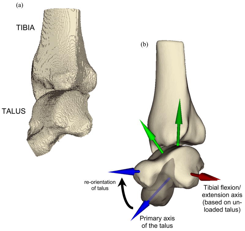
The original relative position and orientation of the two segmented surfaces was as determined by the patient’s relaxed ankle posture during CT scan acquisition (Figure 1). The whole-duty-cycle level walking gait simulation that was implemented required a functionally neutral starting apposition of the tibia and talus. An experienced ankle surgeon prescribed the translations and rotations required to yield this neutral weight-bearing apposition using an interactive medical data visualization program (Data Manager, B3C BioComputing Competence Centre, Bologna, Italy - www.tecno.ior.it/multimod/DataManager/dm_home.html). The repositioning was performed working from biplanar (A-P and lateral) weight-bearing radiographs when available. Otherwise, it was performed as described below, based on unpublished normative data collected as part of a previous study (Tochigi et al. 2005b).
Figure 1.
Smoothing transformed (a) the voxellated segmentation of the relaxed posture intact ankle into (b) a geometric representation of the bone surfaces, suitable for manipulation and contact finite element solution. The re-orientations required to bring the as-segmented ankle into a neutral apposition are represented in (b) also, with the partially translucent image showing the original state of the talus, and the (before and after) coordinate axes showing the spatial transformation.
A local coordinate reference frame, centered within the talus, was first defined based on anatomical landmarks. A provisional ankle flexion/extension axis was defined along a line connecting the centers of circles fitted to the condylar arcs of the talar dome, as described previously by Bottlang et al. (1999). The origin of this axis was defined to split the distance between the two arcs of the talus. A second axis was defined by projection of the primary axis of the talus (visually determined) onto a plane normal to the provisional ankle flexion/extension axis. The tibial and talar surfaces were rotated and translated together so that the talus’ anatomic coordinate system was aligned appropriately with a global reference frame. This entailed aligning the provisional flexion/extension axis along the global x direction, and rotating about this axis to align the primary axis of the talus with the first metatarsal, 15° below horizontal. With the talus thus fixed, the tibia was rotated about the provisional ankle flexion/extension axis so that the angle between the tibial shaft and the floor was 85°.
Finite element mesh generation
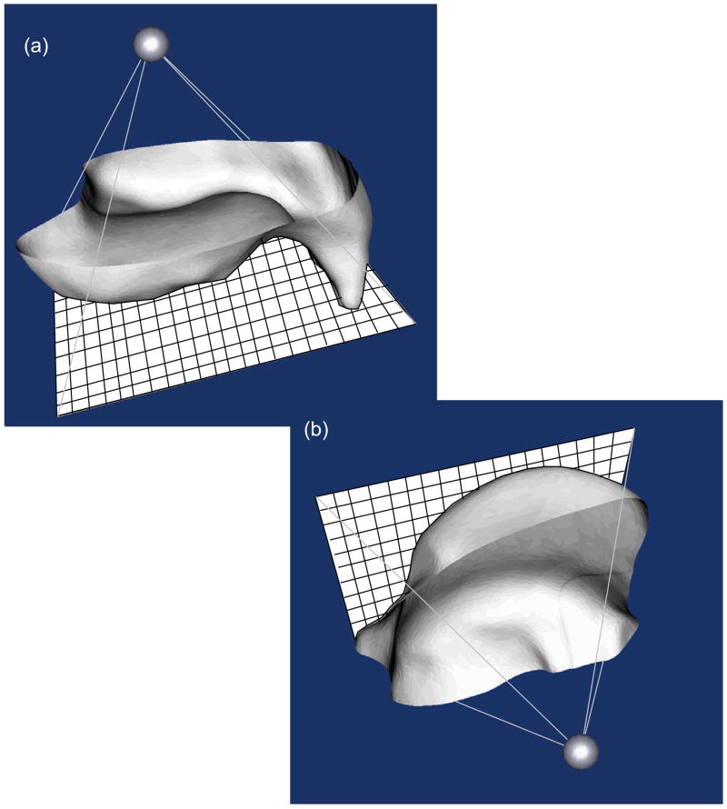
The demands of generating convergent FE meshes for the intact and incongruous ankle joints necessitated the development of custom written computer code, which was done building on our previous work in this area (Grosland and Brown 2002). The Visualization Tool Kit (VTK, www.vtk.org), an open source, freely available software system for computer graphics, image processing, and visualization, was used for this purpose. Beginning with the re-oriented triangulated surface representations of the tibia and the talus, a surface projection-based meshing procedure was implemented. This was accomplished by constructing a bounding pyramid whose base was a transverse meshing plane opposite the articular surface, and whose apex was a user-defined point located beneath the articular surface (Figure 2). The pyramid was then re-sized, rotated about its fixed apex, and positioned to capture desired surface irregularities.
Figure 2.
Triangulated surfaces of (a) the tibia and (b) the talus (both viewed from subchondral perspective) are shaded in grey, with mesh projection planes shown in sold white. Mesh gridlines are depicted in black (not to scale, for the sake of clarity) on the mesh projection planes.
Tibial and talar mesh projection planes were assigned seeding grids with a spatial dimensioning selected by the user, providing the requisite relative refinement needed between the two contact surfaces to ensure robust performance of the master/slave contact paradigm implemented in ABAQUS (ABAQUS Analysis Users Manual, Section 21.2.9, 2003). In particular, the tibia was assigned as the master surface, and an element length ratio of roughly 1:3 was maintained between the tibial and talar meshes. The meshing planes were projected onto the corresponding triangulated surface, effectively morphing seeded mesh grids onto the desired surfaces. In this endeavor, the mesh seeds served as the origins for rays that were projected towards the apex of the pyramid. FE nodes were defined at the nearest point of intersection (whether on a facet, or at a vertex) between projected rays and the triangulated surface. This process was repeated with all mesh seeds, producing a quadrilateral surface mapped onto the original articular surface.
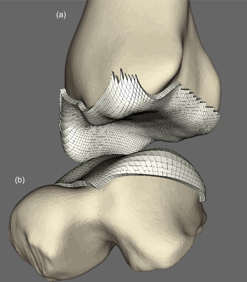
After generating the quadrilateral mesh, point normals for every FE node were calculated. This was done by (i) finding the quadrilaterals sharing a given FE node; (ii) calculating the surface outward pointing normals to those quadrilaterals; and (iii) averaging the normals from these neighboring quadrilaterals. After these meshed surfaces were generated, they were extruded along these point normals to define a zoned cartilage volume with user-specified thickness of 1.5 mm (Figure 3). This methodology was also found to be suitable for meshing the incongruous articular surface associated with tibial plafond fractures (Figure 4).
Figure 3.
Generation of cartilage FE mesh (in white) on (a) tibia and (b) talus from the surfaces morphed on respective bones. NOTE: Ankle is distracted here to aid with visualization.
Figure 4.
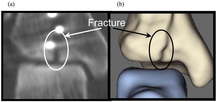
(a) Post-operative CT image of fractured ankle and (b) resulting apposed surfaces, (a) replicating the oblique fracture as seen on CT.
Modeling constraints in whole duty cycle finite element solutions
Finite element solutions were obtained using a commercially available code (ABAQUS Standard 6.4-1, ABAQUS, Inc., Providence, RI, U.S.A.). Deformable contact pairs were defined on the tibial and talar articular cartilage surfaces, and the cartilage was assigned isotropic linear elastic material properties (E=12 MPa and ν=0.42). Coulombic friction (μ=0.01 – Linn 1967) was assumed at the contact surface. Reference nodes, used to control translations and rotations of the assumed rigid tibial and talar subchondral surfaces, were defined so as to coincide (in a loaded configuration) at the midpoint of the two talar condyles, along the provisional ankle flexion/extension axis.
As neither ligamentous structures nor distal structures of the hindfoot were explicitly included in the computational model, the talus was weakly restrained translationally by linear springs (stiffness = 500N/mm) connected to the ground. It was otherwise allowed to freely seat relative to the tibia, throughout a prescribed plantar/dorsi-flexion maneuver. Empirically, to achieve stability during the seating/pre-loading phase, the talus was fixed against rotation about the inversion-eversion and internal-external rotation axes. These restraints were removed, however, for the actual duty cycle simulation, so that the tibio-talar articulation itself controlled talar rotation thereafter. Talar displacement normal to the floor was constrained, and talar flexion/extension was prescribed throughout the simulation.
In the first provisional loading step, the tibia was brought into minimal contact with the weakly constrained talus. To allow the ankle to settle into its precise anatomic apposition, guided by the tibio-talar articulation, a 200 N compressive load was then applied to the tibia in a second provisional loading step (after releasing restraints against talar rotation about the inversion-eversion and internal-external rotation axes). A sequence of thirteen successive loading conditions (loads from 10 to 2800 N and rotations from 5° plantar to 9° dorsiflexion - Stauffer et al. 1977) were next applied to the tibia, to simulate the entire stance phase of level walking gait (Figure 5). As the tibia was rotated about the provisional ankle flexion/ extension axis, the talus was free to rotate as required by the tibio-talar articulation, thereby leading to effective ankle rotations which were not about a fixed axis. The contact nonlinearity, along with the inclusion of friction in the model, rendered this series of quasistatic FE solutions arguably sequence-dependent.
Figure 5.
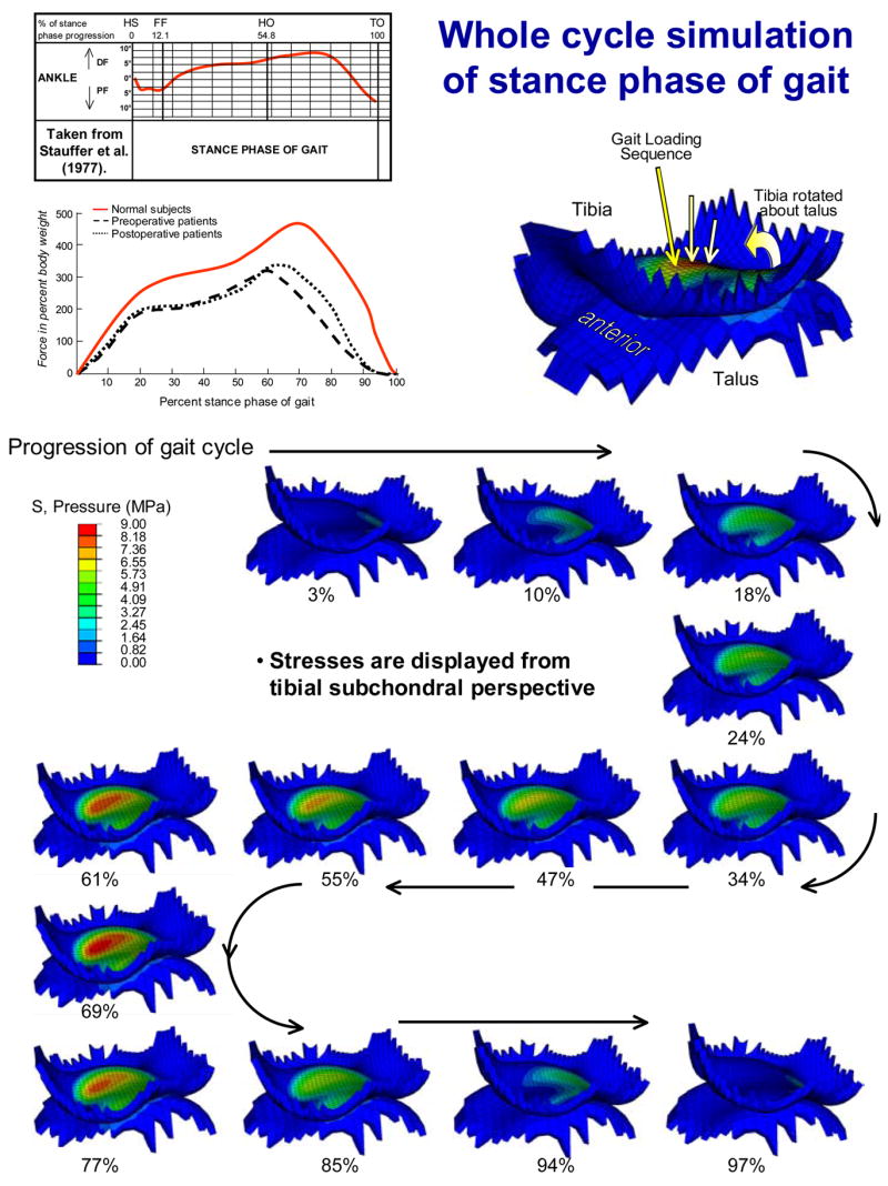
The whole-duty-cycle simulation of the stance phase of level walking gait involved solving a sequence of 13 successive loading increments (axial loads from 10 to 2800 N, applied tibial flexions from 5° plantar- to 9° dorsi-flexion). Each solution is labeled as a percentage of the stance phase progression. NOTE: since the talus is free to rotate, except about the flexion-extension axis, ankle rotation is not about a fixed axis.
Characterization of contact stress exposure
Annual cumulative chronic contact stress exposures were calculated across the tibial articulating surface (or, alternatively, on the talar dome) on a step-by-step basis using the following formula:
where, Pcumulative is the annual cumulative contact stress exposure distribution, expressed in MPa; P̂i are the computed nodal contact stress values at a given increment in the gait cycle, i varying across the 13 load increments; Pd is a contact stress damage threshold (2 MPa – Hadley et al. 1990); and Δti is the resident time, in seconds, associated with a given increment in the gait cycle (assuming a cadence of 58 steps/min - Stauffer et al. 1977). Per-gait-cycle exposures were scaled to meaningful annual service exposures by assuming two million step cycles per year (Schmalzried et al. 2000). This chronic contact stress exposure provides a formal metric of mechano-stimulus abnormality that plausibly correlates with degeneration propensity (Hadley et al. 1990).
RESULTS
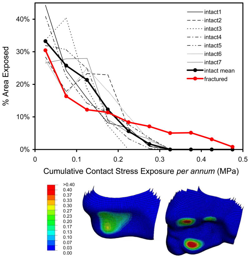
Computed contact stress distributions for the intact ankle joints were continuous and relatively uniform across the contact patch (Figure 5). Except for lightly-loaded instants near the extrema of the motion range, the contact patch stayed relatively consistently located on the tibial articular surface. Peak computed contact stresses were in the range of 9 to 14 MPa, values consistent with experimental recordings in cadaveric ankle preparations (Brown et al. 1994; Vrahas et al. 1994; Steffensmeier et al. 1996). In the illustrative fracture case analyzed, contact stress distributions were discontinuous and more heterogeneous, although the peak values encountered (18 MPa) were not excessively higher. Consistency in computed contact stress exposures for intact ankles was apparent and stood in contrast to the higher magnitude and more focal exposures in the incongruous joint (Figure 6). Area histograms of contact stress exposure (Maxian et al. 1995) were computed for each of the intact tibias, and for the fractured case. There were clearly different patterns exhibited between the incongruous tibia and the family of intact tibias, the former having a larger percentage of the exposed cartilage area experiencing higher magnitude contact stress exposure, with a correspondingly smaller area percentage exposed to lower stresses.
Figure 6.
The fractured ankle exhibited regions with substantially higher contact stress exposures, with a correspondingly smaller area percentage exposed to lower stresses. Inset shows anterior-inferior views of the cumulative contact stress exposure distributions in one intact tibia (left), as well as in the illustrative fracture case (right).
DISCUSSION
The present ankle cartilage stress data represent, to our knowledge, among the first successful applications of intra-articular contact finite element analysis to a clinical series, on a patient-specific basis. The respective normal ankles’ instantaneous contact stress distributions at similar instants of the duty cycle, as well as their cumulative whole-cycle contact stress exposures, showed expected individual variations on common general patterns, as seen in cadaveric experiments (McKinley et al. 2005). Although these analyses are preliminary in nature, the contact stress data from the normal ankles as a group differed appreciably from the situation prevailing for a residual fracture incongruity. Thus, despite the several simplifying assumptions used at this stage of development of the analysis methodology, the present formulation seems amply capable of detecting clinically significant contact aberrations.
Several model simplifications merit additional mention. First, ligamentous structures are not explicitly included. Absence of ligamentous restraint in the FE model is consistent with the results of Tochigi et al. (2005a) that showed that the kinetics of normal ankle motion are dominated by the topography of articular surface contact. Further, under comparable kinetic inputs, the present model’s screw-displacement axode (Figure 7) reasonably replicates that reported by Bottlang et al. (1999). We recognize, of course, that for many situations of ankle joint mechano-pathology, it will be necessary to include ligament representation.
Figure 7.
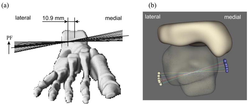
Anterior view of instantaneous screw displacement axes (SDA) (a) measured experimentally (taken from Bottlang et al. (1999)) and (b) computed with the present FE model, plotted for all 13 loading steps onto a single image, show close agreement in the axode of motion. Note that the motion is not a fixed axis rotation, and that the SDA’s in both models pass through the body of the talus, with similar ranges of angular excursion.
A second simplification is that the articular cartilage is modeled as linearly elastic and isotropic. Obviously, a large body of work exists regarding more refined constitutive treatments for cartilage (Mow et al. 1993), particularly as regards the time-dependence of load uptake due to interaction between solid and fluid matrix constituents. However, cartilage’s low permeability is such that, for whole-joint contact simulations at physiologic loading rates, assumptions of linear elastic behavior have generally been viewed as reasonable (Flatow et al. 1994; Genda et al. 2001; Mavcic et al. 2004). Poroelastic cartilage behavior has been incorporated in a single-loading three-dimensional anatomic articular joint contact finite element analysis of the cat patellofemoral joint (Han et al. 2005). As this and other advanced constitutive treatments find their way into broader usage for whole-duty-cycle simulations, it will be important to utilize incremental functional kinetic and kinematic inputs as in the present ankle series. Presumably, the resulting solutions would be even more history-dependent, due also to the constitutive behavior rather than just due to friction and the contact nonlinearity.
CT images of contralateral non-injured ankles are not normally utilized for purposes of fracture treatment, so obtaining them required an ad hoc CT imaging protocol, in addition to standard IRB/HIPAA patient safety and confidentiality assurances. As a practical matter, collecting these images proved to involve an appreciable burden of coordination: initial case presentations for trauma patients occur unpredictably, emergency center staffing both by house physicians and radiology technicians is typically quite fluid, and biomechanical research protocols are not normally an operational consideration in that busy and often hectic environment. Also, major trauma centers typically utilize a range of different CT scanners at any given time, and equipment upgrades are frequent and dynamic. This resulted in variations in CT scan acquisition parameters which had to be accommodated in the analysis procedures, a fact of life when working with patient-specific materials from a clinical setting.
Long-term follow-up data for development of osteoarthritis secondary to habitually elevated contact stresses associated with congenital dislocation of the hip (Hadley et al. 1990) showed that a cumulative stress exposure (from contact stresses exceeding a 2 MPa threshold) above 10 MPa-years was predictive of degeneration. Applicability of these hip-specific numbers to the very different environment of the ankle would obviously be speculative, at best, given these respective joints’ dissimilar propensities for primary versus secondary OA, and given the joint-specificity of cartilage composition and metabolic behavior (Cole and Kuettner 2002). Nevertheless, if the Hadley et al. hip data were to be used as a first approximation, the present area engagement histogram data suggest nominally a 30–40 year additional functional lifetime for the intact ankle surfaces, versus nominally 20 years for this particular incongruous surface case.
Although ankle-specific stress tolerance thresholds remain to be established, the present usage of patient-specific finite element stress computations, coupled with registry of chronic stress exposure, provides a novel quantitative basis for characterizing the degeneration propensity of individual joints, and for characterizing the relative biomechanical efficacy of surgical interventions designed to improve deleterious mechanical abnormalities. Attractive points for model improvement in the near term include modeling spatial variation of cartilage thickness and explicit inclusion of subchondral bony regions.
Acknowledgments
Financial support was provided by grants from National Institutes of Health (AR46601 and AR48939) and from the Arthritis Foundation. We also appreciate the advice and/or technical assistance of numerous individuals, including Ms. Valerie Muehling, Dr. George El-Khoury, Dr. Lee Bennett, Mr. Curtis M. Steyers, Mr. John D. Hill, Mr. Kristofer J. Stewart, Mr. Thomas E. Baer, Dr. Charles L. Saltzman, Dr. Todd O. McKinley, and Dr. Joseph A. Buckwalter. Dr. Fulvia Taddei and Dr. Marco Viceconti (Istituti Ortopedici Rizzoli) kindly provided assistance with Data Manager software.
References
- Adams DJ, Spirt AA, Brown TD, Fritton SP, Rubin CT, Brand RA. Testing the daily stress stimulus theory of bone adaptation with natural and experimentally controlled strain histories. J Biomechanics. 1997;30:671–678. doi: 10.1016/s0021-9290(97)00004-3. [DOI] [PubMed] [Google Scholar]
- Bottlang M, Marsh JL, Brown TD. Articulated external fixation of the ankle: minimizing motion resistance by accurate axis alignment. J Biomechanics. 1999;32:63–70. doi: 10.1016/s0021-9290(98)00143-2. [DOI] [PubMed] [Google Scholar]
- Brown TD, Rudert MJ, Grosland NM. New methods for assessing cartilage contact stress after articular Fracture. Clin Orthop & Rel Res. 2004;423:52–58. doi: 10.1097/01.blo.0000132633.38338.8b. [DOI] [PubMed] [Google Scholar]
- Brown TD, Hurlbut PT, Hale JE, Gibbons TA, Caldwell NJ, Marsh JL, Nepola JV. Effects of imposed hindfoot constraint on ankle contact mechanics for displaced lateral malleolar fractures. J Orthop Trauma. 1994;8:511–519. [PubMed] [Google Scholar]
- Buckwalter JA, Brown TD. Joint injury, repair, and remodeling – Roles in post-traumatic osteoarthritis. Clin Orthop & Rel Res. 2004;423:7–16. [PubMed] [Google Scholar]
- Canny J. A computational approach for edge detection. IEEE Transactions on Pattern Analysis and Machine Intelligence. 1986;8:679–698. [PubMed] [Google Scholar]
- Carter DR, Fyhrie DP, Whalen RT. Trabecular bone density and loading history: regulation of tissue biology by mechanical energy. J Biomechanics. 1987;20:785–795. doi: 10.1016/0021-9290(87)90058-3. [DOI] [PubMed] [Google Scholar]
- Cole AA, Kuettner KE. Molecular basis for difference between human joints. Cell Mol Life Sci. 2002;59:19–26. doi: 10.1007/s00018-002-8401-2. [DOI] [PMC free article] [PubMed] [Google Scholar]
- Felson DT, Lawrence RC, Dieppe PA, Hirsch R, Helmick CG, Jordan JM, Kington RS, Lane NE, Nevitt MC, Zhang Y, Sowers M, McAlindon T, Spector TD, Poole AR, Yanovski SZ, Ateshian G, Sharma L, Buckwalter JA, Brandt KD, Fries JF. Osteoarthritis: New insights. Part 1: The disease and its risk factors. NIH Scientific Conference July 23–24, 1999. Annals of Internal Medicine. 2000;133:635–646. doi: 10.7326/0003-4819-133-8-200010170-00016. [DOI] [PubMed] [Google Scholar]
- Flatow EL, Ateshian GA, Soslowsky LJ, Pawluk RJ, Grelsamer RP, Mow VC, Bigliani LU. Computer simulation of glenohumeral and patellofemoral subluxation. Estimating pathological articular contact. Clin Orthop & Rel Res. 1994;(306):28–33. [PubMed] [Google Scholar]
- Genda E, Iwasaki N, Li G, MacWilliams BA, Barrance PJ, Chao EY. Normal hip joint contact pressure distribution in single-leg standing--effect of gender and anatomic parameters. J Biomechanics. 2001;34:895–905. doi: 10.1016/s0021-9290(01)00041-0. [DOI] [PubMed] [Google Scholar]
- Grosland NM, Brown TD. A voxel-based formulation for contact finite element analysis. Comp Meth Biomechanics and Biomedical Engineering. 2002;5:21–32. doi: 10.1080/10255840290032180. [DOI] [PubMed] [Google Scholar]
- Hadley NA, Brown TD, Weinstein SL. The effects of contact pressure elevations and aseptic necrosis on the long-term outcome of congenital hip dislocation. J Orthop Res. 1990;8:504–513. doi: 10.1002/jor.1100080406. [DOI] [PubMed] [Google Scholar]
- Han S-K, Federico S, Epstein M, Herzog W. An articular cartilage contact model based on real surface geometry. J Biomechanics. 2005;38:179–184. doi: 10.1016/j.jbiomech.2004.03.010. [DOI] [PubMed] [Google Scholar]
- Keyak JH, Meagher JM, Skinner HB, Mote CD., Jr Automated three-dimensional finite element modelling of bone: a new method. J Biomed Eng. 1990;12:389–397. doi: 10.1016/0141-5425(90)90022-f. [DOI] [PubMed] [Google Scholar]
- Linn FC. Lubrication of animal joints. J Bone Joint Surg. 1967;49 Am:1079–1098. [PubMed] [Google Scholar]
- Mavcic B, Slivnik T, Antolic V, Iglic A, Kralj-Iglic V. High contact hip stress is related to the development of hip pathology with increasing age. Clin Biomech. 2004;19:939–943. doi: 10.1016/j.clinbiomech.2004.06.003. [DOI] [PubMed] [Google Scholar]
- Maxian TA, Brown TD, Weinstein SL. Chronic stress tolerance levels for human articular cartilage: two nonuniform contact models applied to long-term follow-up of CDH. J Biomech. 1995;28:159–166. doi: 10.1016/0021-9290(94)00054-8. [DOI] [PubMed] [Google Scholar]
- McKinley TO, Rudert MJ, Koos DC, Pedersen DR, Baer TE, Tochigi Y, Brown TD. Contact stress transients during functional loading of ankle stepoff incongruities. J Biomech. 2005 doi: 10.1016/j.jbiomech.2005.01.036. In Press. [DOI] [PubMed] [Google Scholar]
- Mow VC, Ateshian GA, Spilker RL. Biomechanics of diarthrodial joints: a review of twenty years of progress. J Biomechanical Engineering. 1993;115:460–467. doi: 10.1115/1.2895525. [DOI] [PubMed] [Google Scholar]
- Schmalzried TP, Shepherd EF, Dorey FJ, Jackson WO, dela Rosa M, Fa’vae F, McKellop HA, McClung CD, Martell J, Moreland JR, Amstutz HC. The John Charnley Award. Wear is a function of use, not time. Clin Orthop & Rel Res. 2000;(381):36–46. doi: 10.1097/00003086-200012000-00005. [DOI] [PubMed] [Google Scholar]
- Stauffer RN, Chao EY, Brewster RC. Force and motion analysis of the normal, diseased, and prosthetic ankle joint. Clin Orthop & Rel Res. 1977;(127):189–196. [PubMed] [Google Scholar]
- Steffensmeier SJ, Saltzman CL, Berbaum KS, Brown TD. Effects of medial and lateral displacement calcaneal osteotomies on tibiotalar joint contact stresses. J Orthop Res. 1996;14:980–985. doi: 10.1002/jor.1100140619. [DOI] [PubMed] [Google Scholar]
- Thomas RH, Daniels TR. Ankle Arthritis (Current Concepts Review) J Bone Joint Surg. 2003;85A:923–936. doi: 10.2106/00004623-200305000-00026. [DOI] [PubMed] [Google Scholar]
- Tochigi Y, Rudert MJ, Amendola A, Brown TD, Saltzman CL. Tensile engagement of the peri-ankle ligaments in stance phase. Foot & Ankle Int’l. 2005a doi: 10.1177/107110070502601212. In Press. [DOI] [PMC free article] [PubMed] [Google Scholar]
- Tochigi Y, Suh J-S, Amendola A, Saltzman CL. Ankle Alignment on Lateral Radiographs: Part 2: Reliability and Validity of Measures. Foot & Ankle Int’l. 2005b doi: 10.1177/107110070602700203. In Press. [DOI] [PMC free article] [PubMed] [Google Scholar]
- Van Rietbergen B, Huiskes R, Eckstein F, Ruegsegger P. Trabecular bone tissue strains in the healthy and osteoporotic human femur. J Bone & Mineral Res. 2003;18:1781–1788. doi: 10.1359/jbmr.2003.18.10.1781. [DOI] [PubMed] [Google Scholar]
- Vrahas M, Fu F, Veenis B. Intraarticular contact stresses with simulated ankle malunions. J Orthop Trauma. 1994;8:159–166. doi: 10.1097/00005131-199404000-00014. [DOI] [PubMed] [Google Scholar]


