Abstract
A bilateral dynamic stabilization device is assumed to alter favorable the movement and load transmission of a spinal segment without the intention of fusion of that segment. Little is known about the effect of a posterior dynamic fixation device on the mechanical behavior of the lumbar spine. Muscle forces were disregarded in the few biomechanical studies published. The aim of this study was to determine how the spinal loads are affected by a bilateral posterior dynamic implant compared to a rigid fixator which does not claim to maintain mobility. A paired monosegmental posterior dynamic implant was inserted at level L3/L4 in a validated finite element model of the lumbar spine. Both a healthy and a slightly degenerated disc were assumed at implant level. Distraction of the bridged segment was also simulated. For comparison, a monosegmental rigid fixation device as well as the effect of implant stiffness on intersegmental rotation were studied. The model was loaded with the upper body weight and muscle forces to simulate the four loading cases standing, 30° flexion, 20° extension, and 10° axial rotation. Intersegmental rotations, intradiscal pressure and facet joint forces were calculated at implant level and at the adjacent level above the implant. Implant forces were also determined. Compared to an intact spine, a dynamic implant reduces intersegmental rotation at implant level, decreases intradiscal pressure in a healthy disc for extension and standing, and decreases facet joint forces at implant level. With a rigid implant, these effects are more pronounced. With a slightly degenerated disc intersegmental rotation at implant level is mildly increased for extension and axial rotation and intradiscal pressure is strongly reduced for extension. After distraction, intradiscal pressure values are markedly reduced only for the rigid implant. At the adjacent level L2/L3, a posterior implant has only a minor effect on intradiscal pressure. However, it increases facet joint forces at this level for axial rotation and extension. Posterior implants are mostly loaded in compression. Forces in the implant are generally higher in a rigid fixator than in a dynamic implant. Distraction strongly increases both axial and shear forces in the implant. A stiffness of the implant greater than 1,000 N/mm has only a minor effect on intersegmental rotation. The mechanical effects of a dynamic implant are similar to those of a rigid fixation device, except after distraction, when intradiscal pressure is considerably lower for rigid than for dynamic implants. Thus, the results of this study demonstrate that a dynamic implant does not necessarily reduce axial spinal loads compared to an un-instrumented spine.
Keywords: Lumbar spine, Posterior dynamic implant, Internal fixation device, Finite element method, Biomechanics
Introduction
Degenerated disc disease is often treated by spinal fusion. Several papers show that discs in adjacent segments may also become affected a few years after surgical treatment of a degenerated disc [1, 9, 10, 18, 30]. It is casually hypothesized that the load reduction of a slightly degenerated disc may postpone fusion surgery and adjacent disc disease.
Several flexible posterior spinal fixation systems are clinically used [4, 11, 12, 31, 34]. These so-called dynamic stabilization devices are designed to reduce the disc load. In contrast to solid fusion, the non-fusion systems are intended to maintain intersegmental motions or reduce them to magnitudes found in the intact spine. The Graf ligament system was one of the first such devices used. It consists of a posterior inductile band that serves as a ligament between two pedicle-based screws [5, 8, 14]. The dynamic neutralization system (Dynesys®) has been in clinical use for more than a decade. It comprised titanium alloy pedicular screws, Sulene-PCU spacers and Sulene-PET cords [34]. The cords are introduced through the screw heads, and the spacers are interposed and fixed after pre-loading. The length of the spacers can be intraoperatively adapted to the clinical situation. The Graf ligamentoplasty and the Dynesys® appear to yield similar clinical results [6].
Schmölz et al. [28] determined the degree of stabilization achieved by Dynesys® and the effect of stabilization on the adjacent segment. For the bridged segment, they found that the Dynesys® stabilized the spine and was more flexible than an internal fixator, especially in extension. The motion in the adjacent segments was not influenced when pure moments were applied. In an additional paper [29], the authors described the influence of Dynesys® on intradiscal pressure. In extension, they measured a significantly reduced pressure change in the course of loading both after insertion of Dynesys® and an internal fixator.
The effect of the spacer length of Dynesys® was determined in an in vitro study by Niosi et al. [13]. A 4-mm increase in spacer length led to an increase in intersegmental motion of 30% for axial rotation, 23% for extension, 14% for flexion, and 11% for lateral bending.
Eberlein et al. [3] created a finite element model of an L2–L3 motion segment with Dynesys® and determined the effect of the implant on the overall stiffness. They applied pure moments and found that Dynesys® caused considerable stiffening in flexion and extension and extreme stiffening in torsion.
Mono- and bisegmental internal spinal fixation devices combined with bone grafts were studied by Zander et al. [40, 41] for their effects on the mechanical behavior of the lumbar spine. Using a finite element model, they demonstrated that mono- and bisegmental fixation did not differ markedly and that pretension in the bridged region strongly affected spinal loads.
The finite element method is well suited for parameter studies and allows the determination of many more values than an experimental study. However, validation of the model is mandatory. Validation is only possible for measurable parameters, e.g., intersegmental rotation and intradiscal pressure. Other calculated parameters mostly represent trends due to the simplifications and assumptions necessary to create a finite element model of the lumbar spine, and the absolute values are not always very precise.
In the clinical routine, posterior dynamic implants are considered for different situations. These implants are mostly used when the disc at the affected level is only slightly degenerated. In these cases, the disc height is slightly reduced and the nucleus is compressible [26]. In the very early stage of disc degeneration, disc height is still normal and the disc will show virtually the same mechanical behavior as a healthy one. If the disc height is reduced, the affected level is often distracted by the implant to the height of the healthy disc. This procedure is referred to here as distraction. It is interesting to know how a dynamic implant affects the mechanical behavior of the lumbar spine in different situations. Extensive clinical experience has been gained with rigid implants. Thus, a comparison of the effects of dynamic and rigid implants will disclose the advantages of posterior dynamic implants.
The aims of the present study were to compare a geometrically simplified monosegmental dynamic fixation device and a rigid fixator for their effects on intersegmental rotation, intradiscal pressure, facet joint forces and implant forces. The study also aimed at examining a slightly degenerated disc and a distracted segment for their influence on the affected level and the adjacent cranial segment. An additional aim of the study was to determine the effects of implant stiffness on intersegmental rotation. The models were loaded to simulate standing as well as flexion, extension and axial rotation of the upper body.
Methods
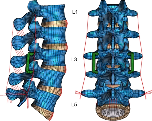
A three-dimensional nonlinear finite element model of the lumbosacral spine was created. It consisted of five vertebrae, five intervertebral discs, and all major ligaments of the lumbar spine (Fig. 1). The geometry was taken from CTs. The annuli fibrosi of the discs were modeled as fiber-reinforced hyperelastic composite (neo-Hookean, C10 = 0.3448, D1 = 0.3) [2]. The fibers were embedded in the ground substance in concentric rings around the nucleus in two times seven layers. They ran to the mid cross-sectional area of the disc under alternating orientation of about 30° and 150°. Fiber stiffness increased from the center to the outer shell [33]. The nuclei pulposi were modeled as incompressible fluid-filled cavities. The curved facet joints had a gap of 0.5 mm and a thin cartilaginous layer. The latter was simulated using soft contact with exponentially increasing contact force and decreasing contact gap [32]. The facet joints could transmit only compressive forces. At full closure, the joints had the same stiffness as the surrounding bone. The ligaments were represented by tension-only spring elements with nonlinear material properties. The material properties of the different tissues were taken from the literature (Table 1) [2, 15, 25–27, 33, 35, 39]. The fibers and ligaments have been described in detail elsewhere [25, 39].
Fig. 1.
Finite element model of the lumbar spine with a degenerated disc and a posterior implant at level L3/L4
Table 1.
Material properties used in this study
| Material | Elastic modulus (MPa) | Poisson’s ratio (–) | Stiffness (N/mm) | Reference | Element type |
|---|---|---|---|---|---|
| Cortical bone | 10,000 | 0.3 | 8-node Hex | ||
| Cancellous bone (transverse isotropic) | 200/140 | 0.45/0.315 | [35] | 8-node Hex | |
| Posterior bony elements | 3,500 | 0.25 | [25, 33] | 8-node Hex | |
| Annulus fibrosus ground substance | Hyperelastic, neo-Hookean C10 = 0.3448, D1 = 0.3 |
[2] | 8-node Hex | ||
| Annulus fibers | Nonlinear and dependent on the distance to the disc center | [25, 33, 39] | Spring | ||
| Nucleus pulposus (healthy) | Incompressible | [26, 39] | Fluid | ||
| Nucleus pulposus (degenerated) | Compressible | [26] | Fluid | ||
| Ligaments | Nonlinear | [15, 26] | Spring | ||
| Pedicle screws (titanium) | 110,000 | 0.3 | Beam | ||
| Dynamic fixation device | 200 | Connector | |||
| Rigid fixation device (titanium) | 110,000 | 0.3 | 83,000 | Beam | |
The model was calibrated using experimental data of Heuer et al. [7] for different anatomical-reduction levels, loading directions and magnitudes. The intact model has virtually the same stiffness as our previous model with a coarser mesh. This model with and without an internal spinal fixator has been extensively validated [19, 39] using experimental data [24, 38]. Test calculations with the present model showed the same good agreement with the experimental results as our previous model with the coarser mesh.
The inferior side of the L5/S1 intervertebral disc was rigidly fixed. The model was loaded with the upper body weight and muscle forces to simulate four loading cases: standing, 30° flexion, 20° extension, and 10° axial rotation to the left. In previous studies the muscle forces for standing, flexion and extension have been estimated [19, 38, 39]. For the loading case of standing, it was assumed that the angle remained unchanged between the superior L1 endplate and the inferior L5/S1 disc side. However, the intersegmental angles at the intervening levels were not constant. An upper body weight of 260 N and a compressive follower load of 200 N were assumed for standing, flexion and extension [16, 24]. The follower load should substitute the stabilizing effect of the local muscle forces. The magnitude of the muscle forces in the erector spinae and rectus abdominis was calculated to gain the desired lumbar spine position [19, 39]. The global muscle forces for axial rotation of the lumbar spine are unknown. Thus 10° axial rotation was predetermined, and a follower load of 500 N was assumed. In this simplified loading case, the follower load represented the local muscle force plus the upper body weight.
After the healthy lumbar spine was studied, a slightly degenerated disc was assumed at L3/L4 with an average height reduction of 20% (Fig. 1). The nucleus pulposus was modeled as compressible. Compressibility of the nucleus was increased from 0.0005 mm²/N (like water) for the healthy disc to 0.0503 mm²/N for the slightly degenerated disc [26].
A paired posterior dynamic implant with fictional material properties was inserted between L3 and L4. No pretension was applied to the implant. The implant was fixed to the vertebrae by two transpedicular screws on each side (Fig. 1). The screws were simulated by beam elements and the longitudinal support by three-dimensional connector elements. The connection between the screws and rods was angular movable. The longitudinal support stiffness of the dynamic implant was 200 N/mm in compression and tension. For comparison, the compressive stiffness of Dynesys® is about 200 N/mm [17]. In a second step, the dynamic implant was replaced by a rigid, angular stable implant of the same geometry with a longitudinal rod made of titanium. With a stiffness of about 83,000 N/mm in tension/compression, the titanium rod was more than 400 times stiffer than the dynamic implant.
The healthy and degenerated disc models were analyzed. Two situations were studied for the degenerated disc with a posterior dynamic implant: without distraction of the bridged region and with distraction to the height of a healthy disc. The latter situation is called distraction. It was simulated by a 2 mm extension of the longitudinal support length between the pedicle screws. This caused a bilateral compressive force of 45 N in the dynamic and 112 N in the angular-stable rigid implant. Distraction as well as a degenerated disc also changed the position of the upper body weight. This was compensated so that the resultant moment relative to L1 was the same as for the healthy disc.
In order to study the effect of implant stiffness on intersegmental rotation the stiffness of the longitudinal rod was varied between 1 and 83,000 N/mm in discrete steps. The latter value represents titanium alloy. A straight longitudinal rod with a diameter of 5 mm was assumed. The connection between the screws and the longitudinal rod was angular movable in this parameter study.
Intersegmental rotations were calculated as well as intradiscal pressures, axial and shear forces in each implant, and facet joint forces. The finite element program ABAQUS, version 6.5-1 (Abaqus, Inc., Providence, RI, USA), was used together with the pre- and postprocessor MSC/PATRAN (MSC Software, Marburg, Germany).
Results
Intersegmental rotation
Intersegmental rotation in the loading plane at implant level (L3/L4) is decreased by inserting a posterior dynamic implant (Fig. 2). In the loading case of standing, rotation is negligible after implant insertion. A rigid implant decreases intersegmental rotation even more, except for standing, where slightly higher values are predicted if the implant is rigid. For a degenerated disc, motion is slightly increased for extension and axial rotation. With an implant, however, disc degeneration only markedly affects intersegmental rotation for axial rotation. Distraction causes higher flexural intersegmental rotation except for axial rotation.
Fig. 2.
Intersegmental rotation at implant level for healthy and degenerated discs, dynamic and rigid implants, distraction, and different loading cases
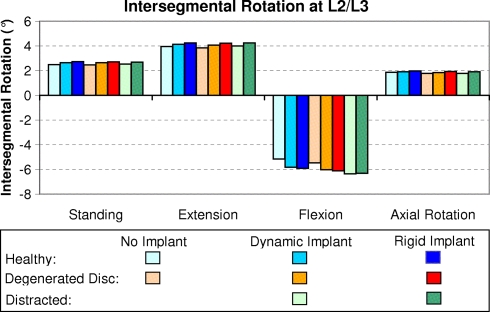
In contrast to the implant level L3/L4, level L2/L3 shows slightly higher intersegmental rotation after insertion of an implant for flexion (Fig. 3). For the other loading cases studied the increase is only minor. A rigid implant leads to slightly higher values than a dynamic one. Disc degeneration has only a minor effect on intersegmental rotation at the adjacent level. Distraction increases the amount of intersegmental rotation only slightly in flexion and has a negligible effect in the other loading cases.
Fig. 3.
Intersegmental rotation at the segment above implant level for healthy and degenerated discs, dynamic and rigid implants, distraction, and different loading cases
Intradiscal pressure
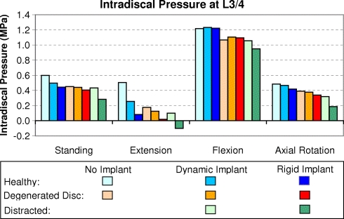
Intradiscal pressure at implant level is more than twice as high for flexion (about 1.2 MPa) than for the other loading cases (Fig. 4). It is markedly affected by a dynamic implant only in the case of extension, when a non-degenerated disc is assumed. The pressure reduction in extension is even more pronounced for a rigid implant. Intradiscal pressure is also reduced by disc degeneration, especially in extension, where it decreases to a level of about 36% compared to the healthy disc. Distraction with a dynamic implant has only a minor effect. In contrast, distraction with a rigid implant decreases intradiscal pressure.
Fig. 4.
Intradiscal pressure at implant level for healthy and degenerated discs, dynamic and rigid implants, distraction, and different loading cases
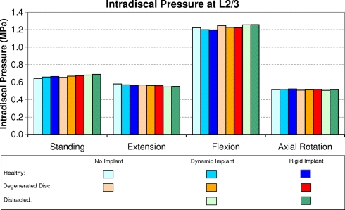
In the adjacent disc L2/3, intradiscal pressure is only slightly affected by a posterior dynamic or rigid implant, by disc degeneration, or by distraction (Fig. 5). The adjacent level is also predicted to show the highest pressure value for flexion.
Fig. 5.
Intradiscal pressure at the adjacent level above the implant for healthy and degenerated discs, dynamic and rigid implants, distraction, and different loading cases
Forces on the implant
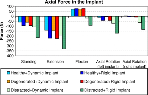
The calculated axial force in the implant is mostly negative, i.e. compressive force (Fig. 6). In a healthy and a degenerated disc, axial tensile forces are calculated for flexion (up to 75 N in each implant). Loads in the rigid fixator are all higher than in the dynamic one. Disc degeneration has only a minor effect on axial implant forces. Axial compressive forces calculated in the dynamic implant range up to 190 N when the bridged region is distracted. The highest force is predicted for extension, while the implant load after distraction is low for flexion. In the rigid fixator, the axial force is especially high when the bridged segment is distracted. The rigid implants show a maximum compressive force of about 330 N for extension. After distraction, compressive force in the implant is predicted for all loading cases, even for flexion.
Fig. 6.
Axial force in the implant for healthy and degenerated discs, dynamic and rigid implants, distraction, and different loading cases
The highest shear forces in the dynamic implant (about 100 N in each implant) are predicted after distraction for axial rotation and flexion. High shear forces are also predicted for a rigid implant when the disc is degenerated. In a healthy and a degenerated disc, shear forces in the implant are low for standing and extension. In our model, no moments were transmitted in the dynamic implant. In the rods of the rigid fixation device, the bending moments were less than 1.5 N m if the bridged segment was not distracted. After distraction, the bending moments varied between 3.4 and 4.3 N m for the loading cases studied. The torsional moments in the rigid fixator rods were highest for the loading case of axial rotation. The maximum torsional moment in a rod was 0.7 N m. The torsional moment in the rigid implant was less than 0.1 N m for standing, flexion and extension.
Facet joint forces
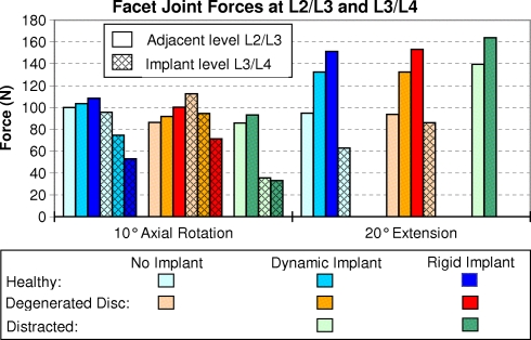
Noteworthy is the fact that facet joint forces at all levels are only predicted for axial rotation and extension. At the adjacent level (L2/L3), they are increased by a dynamic implant and even more by a rigid one, especially for extension (Fig. 7). Disc degeneration leads to slightly lower forces only for axial rotation. Distraction of the bridged segment slightly reduces facet joint forces for axial rotation and increases them for extension.
Fig. 7.
Facet joint forces under axial rotation and extension for healthy and degenerated discs, dynamic and rigid implants, and distraction. The results for the adjacent level L2/L3 and for the implant level L3/L4 (hatched columns) are shown
At implant level (L3/L4), facet joint forces are reduced from about 95 to 75 N by the dynamic implant and to 53 N by the rigid one for axial rotation. After insertion of an implant, the facet joints were unloaded during extension. Disc degeneration leads to slightly higher facet joint forces at implant level during axial rotation. After distraction, the facet joint force was about 35 N at implant level for axial rotation and zero for both the dynamic and the rigid implant in the loading case of extension.
Implant stiffness
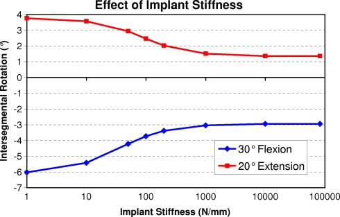
An implant elastic modulus greater than 1,000 MPa has only a minor effect on intersegmental rotation at implant level for flexion and extension (Fig. 8). Only for extremely low values, intersegmental rotation increases markedly. For the other loading cases the effect of implant stiffness was less pronounced. Intersegmental rotation for a dynamic implant with a stiffness of 1 N/mm differs less than 2% of the value for the model without an implant.
Fig. 8.
Effect of implant stiffness on intersegmental rotation at implant level. Note the logarithmic scale of the horizontal axis
Discussion
The effects of monosegmental dynamic and rigid implants on the mechanical behavior of the lumbar spine were studied for a healthy and a degenerated disc as well as after distraction in the case of a degenerated disc.
As in all studies using finite element models of the spine, several simplifications and assumptions had to be made. In a prior study, the finite element model was validated without an implant and with a rigid one. Except at implant level, healthy discs were assumed. Only four loading cases were studied despite the great variety of loads acting on the spine in daily life. Rotation of the L1 vertebra was predetermined and thus remained the same with and without a posterior dynamic implant. Mostly only one set of implant stiffness was assumed for the dynamic implant. Different designs and implant materials may lead to slightly different results. Thus the results show trends, and the absolute values are not necessarily very precise. However, this probably does not affect the main conclusions reached here.
The implant forces and moments calculated for the rigid fixator agree well with those measured in patients [20–23]. The measured values were also much higher in cases where the bridged level was distracted. The calculated intradiscal pressures are also very similar to the values measured in vivo by Wilke et al. [22, 36, 37]. They measured a pressure of about 0.5 MPa for standing, 0.6 MPa for 19° extension, and 1.1 MPa for 36° flexion. The corresponding values calculated for healthy discs without an implant are 0.6 MPa for standing, 0.6 MPa for 20° extension, 1.2 MPa for 30° flexion, and 0.5 MPa for axial rotation. Measured and calculated values agree well.
A posterior dynamic implant reduces intersegmental rotation at implant level for flexion and extension, slightly increases intersegmental rotation at the level above, decreases intradiscal pressure in a healthy disc for extension, and decreases facet joint force at implant level. These effects are slightly more pronounced for a posterior rigid implant. The differences are greater between an intact state and after dynamic implant insertion than between a dynamic and a rigid implant although the implant stiffnesses differ by a factor of more than 400. Thus, similar results can be expected for other bilateral posterior dynamic implants with comparable stiffnesses. In the case of distraction, however, intradiscal pressure is significantly affected by a rigid implant. The relatively small differences raise questions as to whether a dynamic implant really has the advantages that are often expected. A dynamic implant is not angularly stable and thus transfers less or even no bending moment from the longitudinal support to the pedicle screws. Thus, the risk of screw breakage is lower for a dynamic implant than for a rigid one. However, screw loading increases strongly when the bridged segment is distracted (increased longitudinal support length). On the other hand, if the length of the longitudinal support is too short, the preload decreases which may lead to alternating force direction in the pedicle screws and thus to pedicle screw loosening.
When a mildly degenerated disc is assumed, intersegmental rotation is slightly reduced for flexion at implant level and slightly increased at the level above. The nucleus of a degenerated disc is compressible. Intradiscal pressure in such a disc is thus strongly reduced for extension. A slightly degenerated disc has only a minor effect on facet joint force and implant load.
Distraction does not greatly influence intersegmental rotation but has a significant effect on intradiscal pressure at implant level if a rigid implant is used. The pressure values are generally lower for a rigid than for a dynamic implant.
The adjacent segment is only slightly influenced by a posterior implant. However, the facet joint force is increased for axial rotation. This is due to modified rotational angles after insertion of an implant. The rotational angle in the loading plane and thus also the facet joint force are reduced at implant level but increased at the adjacent level.
In this study, the position of the superior endplate of L1 relative to the fixed inferior side of L5/S1 vertebral disc was predetermined for all loading cases. An implant-determined decrease of intersegmental rotation thus caused an increase at other levels. This increase strongly depends on the number of segments considered. Our model consists of five segments, thus the adjacent segment takes over about 25% of the reduction at implant level. This would be higher if fewer segments had been analyzed. Application of pure moments leads to much smaller implant-related differences in the adjacent segments.
In their experimental study, Schmölz et al. [28] applied pure moments in the three main motion planes and found that the Dynesys® stabilized the spine and was more flexible than the internal fixator. This is in agreement with the present study.
This is the first numerical study to compare the effects of posterior dynamic and rigid implants for different grades of disc degeneration with and without implant distraction. It demonstrated that a posterior implant only markedly affects intradiscal pressure at implant level for the loading case of extension and after distraction if a rigid implant is used. The stiffness of a dynamic implant is in-between zero (no implant) and a rigid fixator. However, the stiffness of the studied dynamic implant is already in a range that the differences between an angularly flexible dynamic and an angularly stable rigid implant are mostly small. High axial implant forces are only predicted if the bridged region is distracted. A posterior implant reduces facet joint forces at implant level but has only a minor effect on mechanical behavior at the adjacent level. Thus our study suggests that the difference in the mechanical effect of a paired posterior dynamic or rigid implant is smaller than often expected.
Acknowledgments
The study was financially supported by the Deutsche Forschungsgemeinschaft, Bonn, Germany (Ro 581/17-1) and Synthes GmbH, Oberdorf, Switzerland. Finite element analyses were performed at the Norddeutscher Verbund für Hoch- und Höchstleistungsrechnen (HLRN). The authors thank Dr. J. Weirowski for editorial assistance.
References
- 1.Chou WY, Hsu CJ, Chang WN, Wong CY. Adjacent segment degeneration after lumbar spinal posterolateral fusion with instrumentation in elderly patients. Arch Orthop Trauma Surg. 2002;122:39–43. doi: 10.1007/s004020100314. [DOI] [PubMed] [Google Scholar]
- 2.Eberlein R, Holzapfel GA, Schulze-Bauer CAJ. An anisotropic model for annulus tissue and enhanced finite element analysis of intact lumbar disc bodies. Comp Meth Biomech Biomed Eng. 2000;4:209–229. doi: 10.1080/10255840108908005. [DOI] [Google Scholar]
- 3.Eberlein R, Holzapfel GA, Schulze-Bauer CAJ (2002) Assessment of a spinal implant by means of advanced FE modeling of intact human intervertebral discs. In: Fifth World Congress on computational mechanics. Vienna University of Technology, Vienna, Austria, pp 1–14
- 4.Gardner A, Pande KC. Graf ligamentoplasty: a 7-year follow-up. Eur Spine J. 2002;11(Suppl 2):S157–S163. doi: 10.1007/s00586-002-0436-4. [DOI] [PMC free article] [PubMed] [Google Scholar]
- 5.Graf H. Lumbar stability: surgical treatment without fusion. Rachis. 1992;412:123–137. [Google Scholar]
- 6.Grob D, Benini A, Junge A, Mannion AF. Clinical experience with the Dynesys semirigid fixation system for the lumbar spine: surgical and patient-oriented outcome in 50 cases after an average of 2 years. Spine. 2005;30:324–331. doi: 10.1097/01.brs.0000152584.46266.25. [DOI] [PubMed] [Google Scholar]
- 7.Heuer F, Schmidt H, Klezl Z, Claes L, Wilke HJ (2006) Stepwise reduction of functional spinal structures increase range of motion and change lordosis angle. J Biomech 10.1016/j.jbiomech.2006.1001.1007 (in press) [DOI] [PubMed]
- 8.Kanayama M, Hashimoto T, Shigenobu K. Rationale, biomechanics, and surgical indications for Graf ligamentoplasty. Orthop Clin North Am. 2005;36:373–377. doi: 10.1016/j.ocl.2005.02.013. [DOI] [PubMed] [Google Scholar]
- 9.Kumar MN, Baklanov A, Chopin D. Correlation between sagittal plane changes and adjacent segment degeneration following lumbar spine fusion. Eur Spine J. 2001;10:314–319. doi: 10.1007/s005860000239. [DOI] [PMC free article] [PubMed] [Google Scholar]
- 10.Lee CK. Accelerated degeneration of the segment adjacent to a lumbar fusion. Spine. 1988;13:375–377. doi: 10.1097/00007632-198803000-00029. [DOI] [PubMed] [Google Scholar]
- 11.Mochida J, Toh E, Suzuki K, Chiba M, Arima T. An innovative method using the Leeds–Keio artificial ligament in the unstable spine. Orthopedics. 1997;20:17–23. doi: 10.3928/0147-7447-19970101-05. [DOI] [PubMed] [Google Scholar]
- 12.Mulholland RC, Sengupta DK. Rationale, principles and experimental evaluation of the concept of soft stabilization. Eur Spine J. 2002;11(Suppl 2):S198–S205. doi: 10.1007/s00586-002-0422-x. [DOI] [PMC free article] [PubMed] [Google Scholar]
- 13.Niosi CA, Zhu QA, Wilson DC, Keynan O, Wilson DR, Oxland TR. Biomechanical characterization of the three-dimensional kinematic behaviour of the Dynesys dynamic stabilization system: an in vitro study. Eur Spine J. 2006;15:913–922. doi: 10.1007/s00586-005-0948-9. [DOI] [PMC free article] [PubMed] [Google Scholar]
- 14.Nockels RP. Dynamic stabilization in the surgical management of painful lumbar spinal disorders. Spine. 2005;30:S68–72. doi: 10.1097/01.brs.0000174531.19982.99. [DOI] [PubMed] [Google Scholar]
- 15.Nolte LP, Panjabi MM, Oxland TR (1990) Biomechanical properties of lumbar spinal ligaments. In: Heimke G, Soltesz U, Lee AJC (eds) Clinical implant materials, advances in biomaterials, vol 9. Elsevier, Heidelberg, pp 663–668
- 16.Patwardhan AG, Havey RM, Meade KP, Lee B, Dunlap B. A follower load increases the load-carrying capacity of the lumbar spine in compression. Spine. 1999;24:1003–1009. doi: 10.1097/00007632-199905150-00014. [DOI] [PubMed] [Google Scholar]
- 17.Putzier M, Schneider SV, Funk J, Perka C. Application of a dynamic pedicle screw system (DYNESYS) for lumbar segmental degenerations—comparison of clinical and radiological results for different indications. Z Orthop Ihre Grenzgeb. 2004;142:166–173. doi: 10.1055/s-2004-818781. [DOI] [PubMed] [Google Scholar]
- 18.Rahm MD, Hall BB. Adjacent-segment degeneration after lumbar fusion with instrumentation: a retrospective study. J Spinal Disord. 1996;9:392–400. doi: 10.1097/00002517-199610000-00005. [DOI] [PubMed] [Google Scholar]
- 19.Rohlmann A, Bauer L, Zander T, Bergmann G, Wilke HJ. Determination of trunk muscle forces for flexion and extension by using a validated finite element model of the lumbar spine and measured in vivo data. J Biomech. 2006;39:981–989. doi: 10.1016/j.jbiomech.2005.02.019. [DOI] [PubMed] [Google Scholar]
- 20.Rohlmann A, Bergmann G, Graichen F. Loads on an internal spinal fixation device during walking. J Biomech. 1997;30:41–47. doi: 10.1016/S0021-9290(96)00103-0. [DOI] [PubMed] [Google Scholar]
- 21.Rohlmann A, Bergmann G, Graichen F. Loads on internal spinal fixators measured in different body positions. Eur Spine J. 1999;8:354–359. doi: 10.1007/s005860050187. [DOI] [PMC free article] [PubMed] [Google Scholar]
- 22.Rohlmann A, Claes L, Bergmann G, Graichen F, Neef P, Wilke H-J. Comparison of intradiscal pressures and spinal fixator loads for different body positions and exercises. Ergonomics. 2001;44:781–794. doi: 10.1080/00140130110047657. [DOI] [PubMed] [Google Scholar]
- 23.Rohlmann A, Graichen F, Weber U, Bergmann G. 2000 Volvo Award winner in biomechanical studies: monitoring in vivo implant loads with a telemeterized internal spinal fixation device. Spine. 2000;25:2981–2986. doi: 10.1097/00007632-200012010-00004. [DOI] [PubMed] [Google Scholar]
- 24.Rohlmann A, Neller S, Claes L, Bergmann G, Wilke H-J. Influence of a follower load on intradiscal pressure and intersegmental rotation of the lumbar spine. Spine. 2001;26:E557–E561. doi: 10.1097/00007632-200112150-00014. [DOI] [PubMed] [Google Scholar]
- 25.Rohlmann A, Zander T, Bergmann G. Effect of total disc replacement with ProDisc on the biomechanical behavior of the lumbar spine. Spine. 2005;30:738–743. doi: 10.1097/01.brs.0000157413.72276.c4. [DOI] [PubMed] [Google Scholar]
- 26.Rohlmann A, Zander T, Schmidt H, Wilke H-J, Bergmann G. Analysis of the influence of disc degeneration on the mechanical behaviour of a lumbar motion segment using the finite element method. J Biomech. 2006;39:2484–2490. doi: 10.1016/j.jbiomech.2005.07.026. [DOI] [PubMed] [Google Scholar]
- 27.Rohlmann A, Zilch H, Bergmann G, Kölbel R. Material properties of femoral cancellous bone in axial loading. Part I: Time independent properties. Arch Orthop Trauma Surg. 1980;97:95–102. doi: 10.1007/BF00450930. [DOI] [PubMed] [Google Scholar]
- 28.Schmoelz W, Huber JF, Nydegger T, Claes L, Wilke HJ. Dynamic stabilization of the lumbar spine and its effects on adjacent segments: an in vitro experiment. J Spinal Disord Tech. 2003;16:418–423. doi: 10.1097/00024720-200308000-00015. [DOI] [PubMed] [Google Scholar]
- 29.Schmoelz W, Huber JF, Nydegger T, Claes L, Wilke HJ. Influence of a dynamic stabilisation system on load bearing of a bridged disc: an in vitro study of intradiscal pressure. Eur Spine J. 2006;15:1–10. doi: 10.1007/s00586-005-0032-5. [DOI] [PMC free article] [PubMed] [Google Scholar]
- 30.Seitsalo S, Schlenzka D, Poussa M, Osterman K. Disc degeneration in young patients with isthmic spondylolisthesis treated operatively or conservatively: a long-term follow-up. Eur Spine J. 1997;6:393–397. doi: 10.1007/BF01834066. [DOI] [PMC free article] [PubMed] [Google Scholar]
- 31.Sengupta DK. Dynamic stabilization devices in the treatment of low back pain. Orthop Clin North Am. 2004;35:43–56. doi: 10.1016/S0030-5898(03)00087-7. [DOI] [PubMed] [Google Scholar]
- 32.Sharma M, Langrana NA, Rodriguez J. Role of ligaments and facets in lumbar spinal stability. Spine. 1995;20:887–900. doi: 10.1097/00007632-199504150-00003. [DOI] [PubMed] [Google Scholar]
- 33.Shirazi-Adl A, Ahmed AM, Shrivastava SC. Mechanical response of a lumbar motion segment in axial torque alone and combined with compression. Spine. 1986;11:914–927. doi: 10.1097/00007632-198611000-00012. [DOI] [PubMed] [Google Scholar]
- 34.Stoll TM, Dubois G, Schwarzenbach O. The dynamic neutralization system for the spine: a multi-center study of a novel non-fusion system. Eur Spine J 11 Suppl. 2002;2:S170–178. doi: 10.1007/s00586-002-0438-2. [DOI] [PMC free article] [PubMed] [Google Scholar]
- 35.Ueno K, Liu YK. A three-dimensional nonlinear finite element model of lumbar intervertebral joint in torsion. J Biomech Eng. 1987;109:200–209. doi: 10.1115/1.3138670. [DOI] [PubMed] [Google Scholar]
- 36.Wilke H, Neef P, Hinz B, Seidel H, Claes L. Intradiscal pressure together with anthropometric data—a data set for the validation of models. Clin Biomech. 2001;16:S111–126. doi: 10.1016/S0268-0033(00)00103-0. [DOI] [PubMed] [Google Scholar]
- 37.Wilke HJ, Neef P, Caimi M, Hoogland T, Claes LE. New in vivo measurements of pressures in the intervertebral disc in daily life. Spine. 1999;24:755–762. doi: 10.1097/00007632-199904150-00005. [DOI] [PubMed] [Google Scholar]
- 38.Wilke HJ, Rohlmann A, Neller S, Graichen F, Claes L, Bergmann G. ISSLS prize winner: a novel approach to determine trunk muscle forces during flexion and extension: a comparison of data from an in vitro experiment and in vivo measurements. Spine. 2003;28:2585–2593. doi: 10.1097/01.BRS.0000096673.16363.C7. [DOI] [PubMed] [Google Scholar]
- 39.Zander T, Rohlmann A, Calisse J, Bergmann G. Estimation of muscle forces in the lumbar spine during upper-body inclination. Clin Biomech. 2001;16:S73–S80. doi: 10.1016/S0268-0033(00)00108-X. [DOI] [PubMed] [Google Scholar]
- 40.Zander T, Rohlmann A, Klöckner C, Bergmann G. Comparison of the mechanical behavior of the lumbar spine following mono- and bisegmental stabilization. Clin Biomech. 2002;17:439–445. doi: 10.1016/S0268-0033(02)00040-2. [DOI] [PubMed] [Google Scholar]
- 41.Zander T, Rohlmann A, Klöckner C, Bergmann G. Influence of bone graft characteristics on mechanical behaviour of the spine. J Biomech. 2002;35:491–497. doi: 10.1016/S0021-9290(01)00235-4. [DOI] [PubMed] [Google Scholar]


