Abstract
Resistance exercise has been widely reported to have positive rehabilitation effects for patients with neuromuscular and orthopaedic conditions. This paper presents an optimal design of magneto-rheological fluid dampers for variable resistance exercise device in the form of a knee brace. An intelligent supervisory control for regulating the resistive force or torque of the knee brace has also been studied. The device provides both isometric and isokinetic strength training for the knee.
Keywords: Rehabilitation device, Variable resistance, Intelligent control
1. Introduction
Muscle strength is critically important in maintaining physical function and muscle weakness from normal ageing as well as neurological or traumatic injury. Weakness can seriously impact the mobility and independence of individuals with impaired muscle function. A myriad of studies have shown the beneficial outcome of increased strength through resistance exercise. One benefit of muscle strengthening is to improve mobility [1]. The quadriceps femoris muscle strength gain from exercise could increase dynamic stability and avoid falls for functionally limited elderly individuals while rising from a chair or walking [2,3]. Fisher et al. studied the effect of knee muscle strengthening in patients with knee osteoarthritis (OA) and they found that increased quadriceps femoris strength improved patients’ ability to walk, rise from a chair, and climb stairs [4]. Other studies report similar results that isometric and dynamic resistance exercise improves function and reduces joint pain of patients with knee OA [5,6]. For people with neurologic conditions, strengthening is equally important. In children with cerebral palsy (CP) quadriceps strength is associated with overall motor function and walking speed [7] and resistance exercise has been shown to increase muscle strength and improve motor activity [8]. Andrews et al. found that resistance exercise after acute stroke resulted in an increase in limb muscle strength bilaterally [9]. Teixeira-Salmela et al. found that quadriceps strengthening improved function in patients with hemiparesis following stroke [10].
While muscle strength is clearly important in improving walking ability and reducing impairments associated with many medical conditions, the question remains as to the most efficient manner of providing strengthening in the cost conscious health care system. The delivery of rehabilitation services in the home represents one alternative to reduce cost associated with rehabilitation. However, not many rehabilitation devices are available that provide appropriate resistance to achieve the desired outcome in the home. Typical home-based strengthening devices include elastic bands or sand bag weights that strap around a limb. These are portable and low cost but do not optimize strengthening because they do not take into account the length–tension relationship of muscle. The length–tension relationship states that muscle can produce the highest force when its fibers are at an optimal length [11]. The optimal fiber length is often achieved when the joint that the muscle spans is in its mid-range of motion. This means that as a joint moves through the full range less force is produced at the beginning and the end of the range. The elastic bands provide greater resistance as the tension increases. However, the highest resistance is often at a joint range of motion at which the muscle is weak. The resistance provided by elastic bands cannot be measured making it difficult to precisely prescribe resistance and track progress. Sand bag weights provide the same resistance throughout the joints range of motion and weights are commonly chosen so that a patient can lift the weight through the weakest ranges of motion. This results in less than optimal force generation through most of the range of motion. While isokinetic machines are suitable and multi-functional for optimal muscle resistance exercise, they are large and expensive and not suitable for home use. In addition, they cannot be used when the patient is walking. Low cost rehabilitation devices that provide adequate resistance in an appropriate manner across the range of joint motion are needed to improve functional outcomes both in and out of the home.
In order to investigate the effect of precisely varied resistance training we have developed a variable resistance exercise device (VRED) to facilitate patients’ knee rehabi1itation at home without the need of frequent visits to the clinic. We have fabricated a lightweight, portable, energy efficient and multi-functional device that has a user-friendly human–machine interface. The VRED can be extended to other joint systems with proper mechanical designs. In this study, however, we only focus on its effectiveness for knee rehabilitation. The VRED will be an intelligent device such that after a therapist programs the device, it will provide resistance training for patients without intervention of the therapist. This paper reports the preliminary studies of the VRED.
A key component of the VRED is a variable resistance damper. Several technological options are available to make the damper: hydraulic brake, piezoelectric friction brake, electric motor, and smart fluids including magneto-rheological (MR) fluids. MR fluids offer the best choice due to their lightweight, fast response, energy saving and large resistive force that can be controlled. MR fluids consist of stable suspensions of micro iron particles in a liquid carrier such as oil or water. The magnetic particles respond to the applied magnetic field and change the yield stress of liquid in milliseconds. The magneto-rheological response can be actively controlled in real-time by changing the current input of the electromagnetic coil thereby allowing the provision of variable resistance [12]. The MR fluid dampers are widely used as energy dissipative devices to attenuate structural vibrations. Although MR fluids have fast response times and need a small excitation current, it is generally difficult to precisely predict the dynamic response of an MR damper because it is a highly nonlinear function of the displacement, velocity and current input. Development of algorithms for the force control of the MR damper is one of the objectives of this work.
There have been many studies of MR fluids and devices. A popular constitutive equation of MR fluids is the Bingham model [12]. The modified Bingham polynomial model and Bouc-Wen model are reported to well quantify the hysteresis of MR devices in the literature [13-17]. Artificial neural networks (ANN) are nonparametric models employed to predict damper force and to compute the required voltage in control applications [18,19]. Another important issue related to MR dampers is how to improve their dynamic performance by using proper amplifiers. The current driver technology based on pulse width modulation and integral feedback algorithm can be used to shorten the transient time of the device [20,13]. More information about the characteristics of MR fluids and their applications can be found in [21,12].
In this paper, we present an optimal design study of MR dampers under various constraints based on the Bingham model. We also develop control algorithms to regulate the force output of the MR damper according to the prescription of a therapist. The paper is organized as follows. Section 2 describes the function of the VRED. Section 3 presents an optimal design study of the MR damper. Section 4 presents the control study to regulate the force output of the damper. The simulations and experimental results of the control study are shown in Section 5. Section 6 concludes the paper.
2. Description of variable resistance exercise device
Fig. 1 shows the design of the VRED in the form of a knee brace and Fig. 2 illustrates the device attached on the knee. A MR damper provides the variable resistance to the knee joint. Ideally, the damper should be light so that the patient can carry it with little burden. On the other hand, the damper should be strong enough to lock the knee at a given angle for isometric applications. A linear displacement sensor is used to measure the knee flexion and extension angle. The resistive force can be controlled to meet the exercise requirement as prescribed by the clinician. The thigh component of the VRED is attached to the upper leg, and the shank component to the lower leg. The rotation center of the VRED is aligned to the knee flexion/extension center. Two dampers are positioned on the medial and lateral sides of the leg to provide the balanced torque, and prevent the internal/external torsion and varus/valgus bending.
Fig. 1.
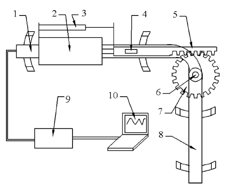
An illustration of the VRED desing: (1) upper part of brace; (2) MR damper; (3) knee position sensor; (4) force sensor; (5) gear rack; (6) rotation center; (7) gear; (8) lower part of brace; (9) signal conditioning and amplifier electronics; (10) control computer.
Fig. 2.
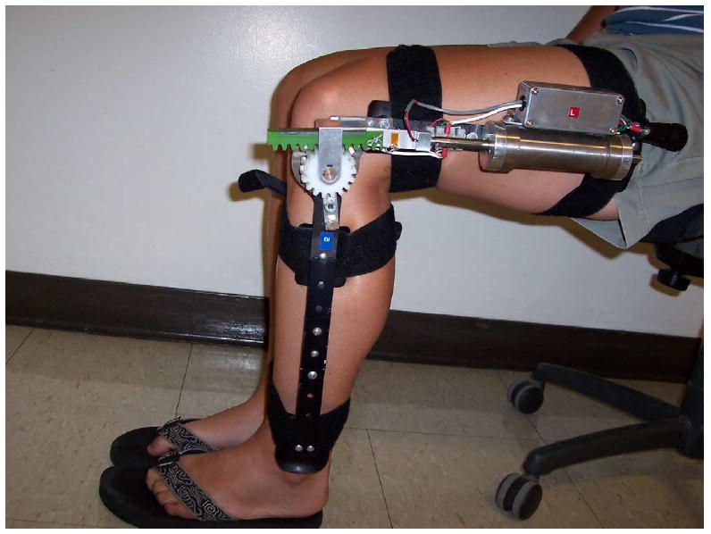
The variable resistance exercise device on the knee.
The VRED works in two modes: the test mode and the exercise mode. In the test mode, the knee is set at a given angle; the dampers provide large enough force to lock the knee. The patient provides a maximum voluntary isometric contraction (MVIC) during knee flexion and extension and the largest torque is recorded. The MVIC is repeated at different ranges of motion to generate a torque profile. In the exercise mode, the physical therapist specifies the exercise effort as a certain percentage of the torque profile. Once programmed, the VRED will work with the patient to exercise automatically. It will produce the exact resistive force based on the prescribed exercise level with the help of an intelligent controller.
3. Optimal design of MR damper
Since most commercial MR dampers are designed for vibration applications, they cannot meet our requirements of low weight, large dynamic range, and long stroke for the VRED. We used the silicone-based MR fluid (MRF-336AG made by Lord Corporation, http://www.lord.com) and developed the customized optimal MR damper for our application.
In the two modes of the VRED, the MR damper operates in the pre-yield and post-yield state. In the pre-yield state, MR fluids exhibit the elastic or viscoelastic property with the field dependent yield stress [22]. In the post-yield state, the viscous flow of MR fluids is governed by the Bingham model [21].
Fig. 3 shows the MR damper with the pressure driven flow. The MR damper force comes from the pressure driven flow of the MR fluid across the valve annular gap between outside spool and inside piston. According to [21], the on-state force fτ and the off-state force fη can be expressed as:
Fig. 3.
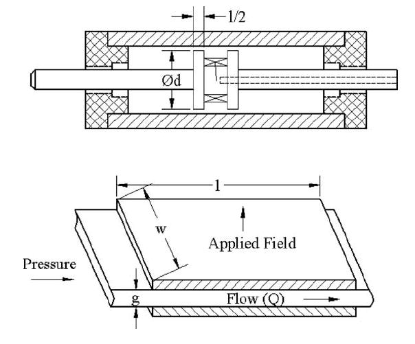
The dual-ended linear damper (above) for the brace with the MR fluid in the mode of valve pressure driven flow (below).
| (1) |
where ΔPη = 12ηQl(g3w) is the pressure drop due to the viscous stress of the Newtonian steady laminar flow, ΔPτ = (cτyl)/g the pressure drop due to the applied magnetic field, Q the volumetric flow rate, η the dynamic viscosity which is a function of the flow shear rate γ̇ without the applied field, c a yield stress correction factor (about 2.5), τy the yield stress determined by the magnetic flux density, and Spiston is the cross area of the piston.
Neglecting the cross area of the shaft, we obtain the following geometric relations,
| (2) |
where w is the piston circumference, d the diameter of the piston, U the piston moving velocity, and g is the magnetic gap. λ = fτ/fη is known as the dynamic ratio of the MR damper. For the design given in Fig. 3, we have
| (3) |
The weight of the MR damper comes from the piston, the spool, the shaft, the cover and the fluid. For a given specified force output fgiven and the dynamic ratio λgiven, we would like to minimize the weight of the damper. This leads to the following optimization problem: minimize the weight of the MR damper with respect to the parameters w and g subject to the following constraints,
| (4) |
Since the on-state force fτ is often much larger than the off-state force fη, the first constraint can be simplified to fτ ≥ fgiven.
An explicit optimization solution is difficult to obtain for the general case when η is a function γ̇ which is often unknown. In the present application, the shear rate γ̇ is small, we assume that η is constant and the yield stress τy is taken to be the value when the MR fluid is saturated with the flux density. Under these assumptions, we obtain the optimal circumference and magnetic gap as:
| (5) |
4. Control algorithm for force tracking
Next, we consider the dynamic performance of the VRED in force tracking. Fig. 4 shows an experimental hysteresis of the VRED force output at a flexion velocity 100°/s. The corresponding piston velocity of the MR damper is 5 cm/s. In the test, we increase the coil voltage from 0 to 10 V at 1 V increments and then decrease it to zero. The MR damper force at each voltage or the corresponding current is recorded. To eliminate the coil inductance effect, after we change the voltage, we wait for one minute before recording the force. The force reading over one complete stroke for each current is averaged. This averaged force is plotted against the current in Fig. 4. An off-state force at zero current and the hysteresis of the on-state force are clearly observable in the figure.
Fig. 4.
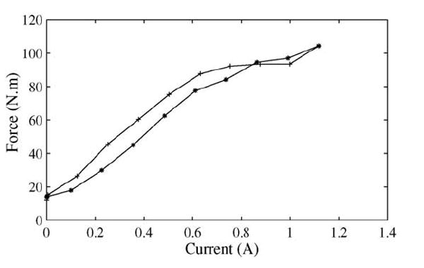
Experimental results of the hysteresis of the VRED force response as a function of the coil input current: (*) current increase; (+) current decrease.
The effect of flexion velocity on the force output of the VRED is studied next. In this case, the force of the VRED includes a off-sate component dependent on the flexion velocity, and the on-state one dependent on the current. The experimental results of the VRED forces are plotted in Fig. 5. As can be observed from the figure, the total resistance force increases as flexion velocity increases even when the current is held constant.
Fig. 5.
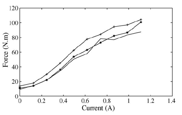
Experimental results of the VRED force response as a function of velocity. Solid line: 40°/s. (*) 100°/s. (+) 200°/s.
In the following, we assume that the MR fluid and iron core of the coil operate in the lower linear range of the B–H curve with the applied magnetic intensity far away from saturation. This assumption agrees with the experimental conditions.
4.1. Plant model
In order to develop control algorithms to regulate the VRED force output, we need a dynamic model of the system. Recall that the total resistive force of the MR damper is f = fτ + fη. The off-state force can be expressed as fη = C1 sgn(ẋ) + C2ẋ, where C1 represents a constant force due to static friction and C2ẋ is the viscous force. ẋ is the joint angular velocity.
For the on-state force, we use an electric RL circuit to model the MR damper coil [23,24], where L is the self-inductance of the coil, and R is the resistance of the coil. The current in the circuit is regulated by the applied input voltage u. Based on the experimental observations, we assume that the resistance R is constant because the damper temperature varies very little during exercise, and that the self-inductance L is also constant because the present application is well within the linear range of the B–H curve as discussed earlier.
The on-state force is related to the current by fτ = sgn(ẋ)k(LI)p, where could be interpolated from the graph presented in [21] or be calculated directly from the experimental result, N is the number of coil turns, and By is the magnetic flux density corresponding to the MR fluid yield stress τy. The power index p is reported to range from 1.5 to 1.75 in the low to intermediate magnetic fields [21]. Here we let the coefficient C3 absorb the factor kLp and obtain the total force expression f = C1 sgn(ẋ) + C2ẋ + C3 sgn(ẋ)Ip, where 1 ≤ p ≤ 2. In this formulation, we use the current I as the control input.
4.2. Supervisory control
In general, C1, C2, C3, and p are unknown and should be estimated. One way to do this is to use online adaptation algorithms to estimate them. The computational demand of the parameter adaptation on the real-time controller can limit the bandwidth of the system significantly. In this paper, we consider the supervisory control [25-28].
The supervisory control proposes to use several sets of parameters of the model based on the previous system identification. For each set of parameters a control is designed to achieve the desired performance. A supervisor monitors the real-time response of the system, selects a plant model according to a switching criterion and implements the corresponding control.
In this work, we only deal with the uncertain power index p. We choose two values for p to demonstrate the concept, namely p = 1 and p = 2, and design a control for the two cases. To focus on the study of the effect of p, we fix a set of parameters C1, C2 and C3 denoted by the lower case c1, c2 and c3 in the control design.
Two controls for the case with p = 1 and p = 2 have been designed, tested and proven to be stable. Next, we briefly outline how to switch between the two controls in real-time.
4.2.1. Switching logic
Let us define the prediction errors of the damper force as
| (6) |
where fm,n is the measured damper force at the nth sample period. Consider a performance index θ governed by the following equation
| (7) |
where j = 1, 2 and 0 < κ < 1.
The digital version of the hysteresis switching logic in [27] can be stated as
Case 1, pn−1 = 1: if θ1,n > (1 + h) θ2,n, pn = 2; else pn = 1.
Case 2, pn−1 = 2: if θ2,n > (1 + h) θ1,n, pn = 1; else pn = 2.
Note that h is chosen to be a small positive number 0.05 for avoiding chattering, which behaves like the boundary layer parameter in sliding controls [29]. Since both the controls for p = 1 and p = 2 are stable, we shall only need to prove that the switching logic will only result in a finite number of switchings in a given time period. The proof presented below follows the same line as in [27].
Define a variable θ̄p,n = θp,n/κn. Let the initial conditions of the performance index be θp,0 > 0 for both p = 1 and p = 2. Then, θ̄p,0 = θp,0 > 0. From Eq. (7), we obtain an equation for θ̄p,n as
| (8) |
Hence, θ̄p,n is monotonically increasing and positive for all n > 0. Therefore, θp,n will not be oscillatory and will converge as the tracking error ep,n converges. This implies that in any time interval, there will be only a finite number of switchings.
5. Simulation and experimental results
Before we present the simulation and experimental results, we will discuss the hardware and its limits. The dc voltage applied to the coil is within the range of 0–12 V. We have used anti-integral windup to prevent overshoot in simulations and experiments. The resistance R of the coil is measured by a multimeter. The inductance L is identified from the coil transient response to a step voltage. The current I in the coil is measured through the voltage across a 1 Ω resistor in serial with the coil. Prior to the experiments, the resistive force and flexion angle of the VRED are calibrated.
The angular velocity of the knee is obtained by differentiating a low-pass filtered angle measurement. The expression for the velocity is given by ẋn = 0.6ẋn−1 + 100(xn − xn−1). The sampling frequency of the digital controller is 250 Hz both in simulations and experiments.
The parameters for the control simulations and experiments are as follows: c1 = 8, c2 = 0.05, c3 = 90, R = 10, L = 0.195, α = 0.815. To establish a baseline for validating the control design, we assume that the actual plant parameters are C1 = 7, C2 = 0.05, C3 = 88 and p = 1.3. The response of the actual plant is simulated for a range of flexion velocities from 0 to 400°/s. The angle is in the range from 15 to 90°.
Fig. 6 shows the simulated step force tracking, and Fig. 7 shows the sinusoidal force tracking. The figures show that the supervisory control properly switches the plant model and the corresponding control. The tracking performance is improved after each switching without overshoot. In addition, the control output is very smooth and compensates the variation of the flexion velocity. Note that we have converted the time signal to the corresponding angular position in the figures.
Fig. 6.
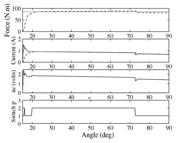
Simulation of the step response. (Solid line) desired force or current. (Dashed-line) actual force or current.
Fig. 7.
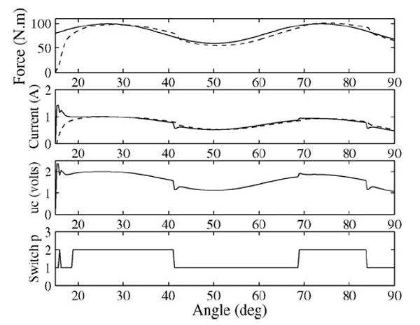
Simulation of the response to a sinusoidal reference. (Solid line) desired force or current. (Dashed-line) actual force or current.
We implement the simulated control in the experiment without any modification. The experimental control results of the step force tracking are shown in Fig. 8, and of the variable reference tracking in Fig. 9. The results indicate that the force response of the system is bounded and the force tracking is accurate with fast response. The low-level overshoot in the experimental results is likely due to the hardware delay. The irregular curve in the experimental plot at beginning comes from disturbances of the measurement when the angular reading is small and the signal-to-noise ratio is also small. After about two sample periods, the irregularity goes away.
Fig. 8.
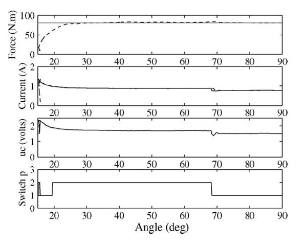
Experimental results of the step response. (Solid line) desired force or current. (Dashed-line) actual force or current.
Fig. 9.
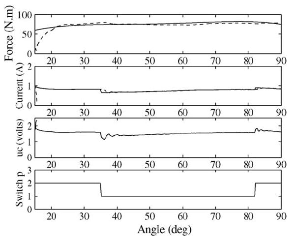
Simulation of the response to a variable reference. (Solid line) desired force or current. (Dashed-line) actual force or current.
6. Conclusions
We have presented an optimal design of MR dampers for variable resistance exercise device. The dampers have been integrated with a knee brace. An intelligent supervisory control for regulating the resistive force or torque of the dampers has also been studied. The supervisory control effectively deals with system uncertainties of the brace dynamic model, and achieves excellent force tracking performance. The VRED will be tried in a clinic setting in the near future. Experimental data from the clinic trials will be used to further study the human–machine interaction in order to develop an intelligent rehabilitation device.
Acknowledgments
This work is supported by a grant (5 R21 HD040956-03) from the National Institute of Health.
References
- 1.Madsen OR, Lauridsen UB, Sorensen OH. Quadriceps strength in women with a previous hip fracture: relationships to physical ability and bone mass. Scand J Rehabil Med. 2000;32:37–40. doi: 10.1080/003655000750045721. [DOI] [PubMed] [Google Scholar]
- 2.Scarborough DM, Krebs DE, Harris BA. Quadriceps muscle strength and dynamic stability in elderly persons. Gait Posture. 1999;10:10–20. doi: 10.1016/s0966-6362(99)00018-1. [DOI] [PubMed] [Google Scholar]
- 3.Ryushi T, Kumagai K, Hayase H, Abe T, Shibuya K, Ono A. Effect of resistive knee extension training on postural control measures in middle aged and elderly persons. J Physiol Anthropol Appl Human Sci. 2000;19:143–9. doi: 10.2114/jpa.19.143. [DOI] [PubMed] [Google Scholar]
- 4.Fisher NM, Gresham GE, Abrams M, Hicks J, Horrigan D, Pendergast DR. Quantitative effects of physical therapy on muscular and functional performance in subjects with osteoarthritis of the knees. Arch Phys Med Rehabil. 1993;74:840–7. doi: 10.1016/0003-9993(93)90011-x. [DOI] [PubMed] [Google Scholar]
- 5.Topp R, Woolley S, Hornyak J, Khuder S, Kahaleh B. The effect of dynamic versus isometric resistance training on pain and functioning among adults with osteoarthritis of the knee. Arch Phys Med Rehabil. 2002;83:1187–95. doi: 10.1053/apmr.2002.33988. [DOI] [PubMed] [Google Scholar]
- 6.Bischoff HA, Roos EM. Effectiveness and safety of strengthening, aerobic, and coordination exercises for patients with osteoarthritis. Curr Opin Rheumatol. 2003;15:141–4. doi: 10.1097/00002281-200303000-00010. [DOI] [PubMed] [Google Scholar]
- 7.Damiano DL, Martellotta TL, Sullivan DJ, Granata KP, Abel MF. Muscle force production and functional performance in spastic cerebral palsy: relationship of cocontraction. Arch Phys Med Rehabil. 2000;81:895–900. doi: 10.1053/apmr.2000.5579. [DOI] [PubMed] [Google Scholar]
- 8.Dodd KJ, Taylor NF, Damiano DL. A systematic review of the effectiveness of strength-training programs for people with cerebral palsy. Arch Phys Med Rehabil. 2002;83:1157–64. doi: 10.1053/apmr.2002.34286. [DOI] [PubMed] [Google Scholar]
- 9.Andrews AW, Bohannon RW. Short-term recovery of limb muscle strength after acute stroke. Arch Phys Med Rehabil. 2003;84:125–30. doi: 10.1053/apmr.2003.50003. [DOI] [PubMed] [Google Scholar]
- 10.Teixeira-Salmela LF, Olney SJ, Nadeau S, Brouwer B. Muscle strengthening and physical conditioning to reduce impairment and disability in chronic stroke survivors. Arch Phys Med Rehabil. 1999;80:1211–8. doi: 10.1016/s0003-9993(99)90018-7. [DOI] [PubMed] [Google Scholar]
- 11.Gordon AM, Huxley AF, Julian FJ. The variation in isometric tension with sarcomere length in vertebrate muscle fibres. J Physiol. 1966;184:170–92. doi: 10.1113/jphysiol.1966.sp007909. [DOI] [PMC free article] [PubMed] [Google Scholar]
- 12.Carlson JD, Jolly MR. MR fluid, foam and elastomer devices. Mechatronics. 2000;10:555–69. [Google Scholar]
- 13.Yang G, Carlson JD, Sain MK, Spencer BF., Jr Large-scale MR fluid dampers: modeling and dynamic performance considerations. Eng Struct. 2002;24:309–23. [Google Scholar]
- 14.Dimock GA, Yoo J-H, Wereley NM. Quasi-steady Bingham biplastic analysis of electrorheological and magnetorheological dampers. J Intell Mater Syst Struct. 2002;13:549–59. [Google Scholar]
- 15.Choi SB, Lee SK, Park YP. A hysteresis model for the field-dependent damping force of a magnetorheological damper. J Sound Vibr. 2001;245:375–83. [Google Scholar]
- 16.Dyke SJ, Spencer BF, Jr, Sain MK, Carlson JD. Modeling and control of magnetorheological dampers for seismic response reduction. Smart Mater Struct. 1996;5:565–83. [Google Scholar]
- 17.Spencer BF, Jr, Dyke SJ, Sain MK, Carlson JD. Phenomenological model for magnetorheological dampers. J Eng Mech. 1997;123:230–8. [Google Scholar]
- 18.Chang C-C, Zhou L. Neural network emulation of inverse dynamics for a magnetorheological damper. J Struct Eng. 2002;128:231–9. [Google Scholar]
- 19.Chang C-C, Roschke P. Neural network modeling of a magnetorheological damper. J Intell Mater Syst Struct. 1999;9:755–64. [Google Scholar]
- 20.Milecki A. Investigation of dynamic properties and control method influences on MR fluid dampers’ performance. J Intell Mater Syst Struct. 2002;13:453–8. [Google Scholar]
- 21.Jolly MR, Bender JW, Carlson JD. Proceedings of SPIE 5th Annual International Symposium on Smart Structures and Materials; San Diego, California. [Google Scholar]
- 22.Weiss KD, Carlson JD, Nixon DA. Viscoelastic properties of magneto- and electro-rheological fluids. J Intell Mater Syst Struct. 1994;5:772–5. [Google Scholar]
- 23.Vaughan ND, Gamble JB. The modeling and simulation of a proportional solenoid valve. J Dyn Syst Meas Control. 1996;118:120–5. [Google Scholar]
- 24.Elmer KF, Gentle CR. A parsimonious model for the proportional control valve. Proceedings of the Institution of Mechanical Engineers, Part C. 2001;215:1357–63. [Google Scholar]
- 25.Morse AS. Supervisory control of families of linear set-point controllers—Part 1: exact matching. IEEE Trans Autom Control. 1996;41:1413–31. [Google Scholar]
- 26.Morse AS. Supervisory control of families of linear set-point controllers—Part 2: robustness. IEEE Trans Autom Control. 1997;42:1500–15. [Google Scholar]
- 27.Hespanha JP, Liberzon D, Morse AS. Logic-based switching control of a nonholomic system with parametric modeling uncertainty. Syst Control Lett. 1999;38:167–77. [Google Scholar]
- 28.Hespanha JP, Liberzon D, Morse AS. Hysteresis-based switching algorithms for supervisory control of uncertain systems. Automatica. 2003;39:263–72. [Google Scholar]
- 29.Slotine J-JE, Li W. Applied Nonlinear Control. New Jersey: Englewood Cliffs; 1991. [Google Scholar]


