Abstract
The utriculo-endolymphatic valve was discovered by Bast in 1928. The function of Bast’s valve is still unclear. By means of orthogonal-plane fluorescence optical sectioning (OPFOS) microscopy 3D-reconstructions of the valve and its surrounding region are depicted. The shape of the duct at the utricular side is that of a flattened funnel. In the direction of the endolymphatic duct and sac this funnel runs into a very narrow duct. The valve itself has a rigid ‘arch-like’ configuration. The opposing thin, one cell-layer thick, utricular membrane is highly compliant. We propose that opening and closure of the valve occurs through movement of the flexible base/utricular membrane away from and toward the relatively rigid valve lip.
Keywords: Utriculo-endolymphatic valve, Bast’s valve, OPFOS, Imaging, Endolymphatic system, 3D-reconstruction
Hypothesis
The bottom or opposing wall of the uticulo-endolymphatic (Bast’s) valve is the moving and thus functional part of the valve.
Background
At the utricular end the utricular duct has a valve-like opening. This structure was discovered by Bast [3], who called it the utriculo-endolymphatic valve. It is since then also called Bast’s valve. The morphology of the valve has been researched in humans and several mammalians [1, 5, 10].
The function of Bast’s valve is still unclear. Bast himself suggested the closure of the utricular duct as the main function [3, 4]. Bachor and Karmody [2] follow Bast’s view, postulating that decreasing pressure in the whole endolymphatic system, secondary to collapse of the ductus reuniens, causes closure of the valve to prevent more loss of endolymph from the utricular system. Zechner [20] proposes that dysfunction of the valve causes endolymphatic hydrops.
In this paper orthogonal-plane fluorescence optical sectioning (OPFOS) microscopy [6, 15–17] was used to obtain detailed three-dimensional reconstructions of Bast’s valve and the surrounding region in the intact guinea pig inner ear, as it is a technique capable of visualizing bone as well as soft tissue structures with high resolution, and is non-invasive.
Material and methods
Specimen preparation
Two healthy female albino guinea pigs (Harlan Laboratories, UK), weighing 450 g, were used. Animal care and use were approved by the Experimental Animal Committee of Groningen University, protocol No. 2883, in accordance with the principles of the Declaration of Helsinki.
The animals were terminated by lethal administration of sodium pentobarbital. After decapitation the bullas were dissected and fixated in a 10% formalin solution, neutrally buffered. Then the bullas were rinsed in aqua-dest. Decalcification in ethylenediaminetetraacetic acid 10% solution (EDTA; Sigma, ED5SS, pH 7.4) took place at a temperature of 50°C in a microwave oven (T/T MEGA microwave histoprocessor, Milestone) in eight sessions of 6 h. After decalcification the bullas were again rinsed with aqua-dest and dehydrated in a graded seven-step ethanol series (30%, 50%, 70%, 90%, 96%, 100%, and 100%).
Spalteholz fluid, a 5:3 solution of methyl salicylate (Sigma, M-6752) and benzyl benzoate (Sigma, B-6630) [14], was thereafter used to achieve transparency of the specimen. The clearing process consisted of application of a succession of Spalteholz-ethanol solutions, 24 h each. The Spalteholz fluid fraction in the clearing session was 25%, 50%, 75%, 100%, 100%, respectively. Hereafter the specimen was dyed in a fluorescent dye bath of Rhodamine-B Isothiocyanate (RITC; Sigma, R-1755). RITC absorbs maximally at 570 nm and emits at 595 nm. The dye bath was prepared by dissolving 1.0 mg/ml RITC into ethanol, followed by dilution in Spalteholz fluid to a final dye concentration of 5 × 10⁻⁴ mg/ml [15, 16] (Voie 2003). The specimen was dyed for four days.
OPFOS imaging system
A schematic diagram of the optical setup of our custom-made OPFOS imaging device is shown in Fig. 1 [6]. Laser light, originating from a green frequency doubled Nd:YVO4 neodymium-laser (model DPGL-2050, Suwtech), with an emission wavelength of 532 nm and 52 mW maximal power, is expanded into a parallel beam of 28 mm diameter by a Galilean beam expander (BE, model 336, Spectra-Physics). The broadened and spatially filtered light falls onto a specially designed cylindrical lens (CL, custom-made by LiteTec Ltd., Essex, UK) of 30 × 30 mm and 80 mm focal length, which focuses the light along a single dimension (Z), thus creating a hyperbolic light pattern along the X-axis. Near the center of this focus, we can locally approximate the light intensity profile as a sheet of light in the X–Y plane, which will perform virtual slicing of a specimen object (O). In the plane where the object is sectioned by the sheet of light, the specimen emits fluorescence light, which is recorded by a CCD-camera (C, Firewire FO442BIC, Foculus) in the direction orthogonal to the light plane. In this way, a 2D image of a virtual section within the object is obtained. For the specimen to be compatible with the OPFOS method, the above described specimen preparation is necessary to make the object transparent, refraction index matched and fluorescent. In our setup the specimen is positioned inside a container with optical quality glass windows at the laser and CCD side, and filled with Spalteholz fluid, and can be positioned within the container by an object translation stage (OTS). Between recordings the object (and not the container) is moved along the Z-axis in small slicing steps with a high-precision DC-motor driven translation stage with position encoder (M112.1 High-Resolution Micro-Translation Stage with C862 Mercury II DC-Motor Controller, PI Polytec). A long working distance microscope objective lens (OL) with good numerical aperture (M Plan APO × 5, NA = 0.14, Mitutoyo) projects the fluorescence image on the CCD. A colour filter (Kenko R1 SR-60) placed before the objective lens blocks scattered laser light and transmits fluorescence light.
Fig. 1.
Orthogonal-Plane Fluorescence Optional Sectioning (OPFOS) set-up. (BE: beam expander, FS: field stop, CL: cylindrical achromat, O: object, OTS: object translation stage, FTS: focusing translation stage, OL: objective lens with colour filter, CCD = charge coupled device camera)
The virtual slicing is performed by a ‘plane’ with 3 μm 1/e²-thickness resolution in the center of the image and slightly thicker at the edges (less than 10 μm), with slicing steps of 2 μm, followed by storage in a personal computer. The two-dimensional stored images were processed with an IMOD (http://bio3d.colorado.edu/imod) software package for 3D-reconstruction. Input of relevant contours in each 2D-image was manually performed with a writing tablet (Wacom Cintiq 15X).
Results
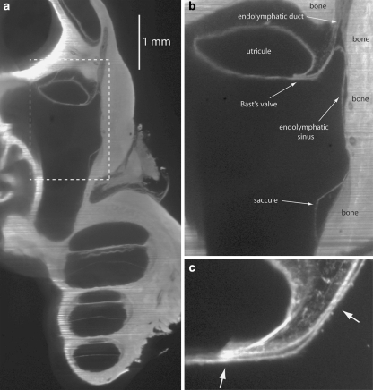
Figure 2a shows an OPFOS image of a cross-section of part of the guinea pig inner ear. Figure 2b is an enlargement of the part of Fig. 2a inside the dashed box, in which Bast’s valve and its surrounding structures are clearly visible. Saccule, endolymphatic sinus, utricule and endolymphatic duct are filled with endolymph. Walls of the endolymphatic space are on the right side of Fig. 2b connected to bone (dense; non-compliant). The opposite walls are adjacent to perilymph (hypodense; compliant). Connective tissue (medium density; non-compliant) is present inside the lip of Bast’s valve and between the upper side of the utricule and bone. Figure 2c is another OPFOS image, showing Bast’s valve in detail.
Fig. 2.
(a) 2D OPFOS-image of the region around Bast’s valve and the utricular duct, obtained with another OPFOS setup [7] than for (c) and following. The dashed box is shown in a larger magnification in (b), (b) Dashed box in (a) shown in a larger magnification, (c) 2D OPFOS-image of Bast’s valve. The arrows point toward very narrow passages
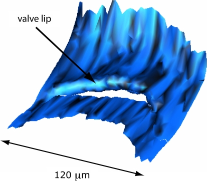
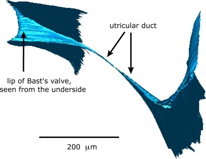
Figure 3 shows a 3D-reconstruction of the entrance of Bast’s valve as seen from inside the utricle. The proximal end of the valve shows a rather rigid ‘arch-like’ configuration. Figure 4 shows a 3D-reconstruction of walls of Bast’s valve and the utricular duct. The shape of the utricular duct at the utricular side is that of a flattened funnel. This funnel quickly runs into a very narrow duct.
Fig. 3.
3D-Reconstruction of Bast’s valve as seen from inside the utricule
Fig. 4.
3D-Reconstruction of walls of Bast’s valve and the utricular duct. The shape of the utricular duct at the utricular side is that of a flattened funnel. This funnel runs into a very narrow duct
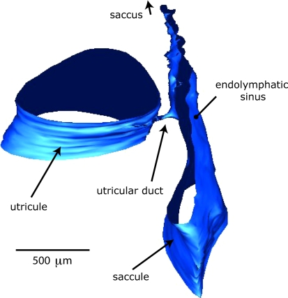
Figure 5 is a 3D-reconstruction of part of the outer walls of the utricle and utricular duct. It again shows the small caliber of the utricular duct in relation to the size of surrounding structures.
Fig. 5.
3D-Reconstruction of part of the outer walls of the utricle and utricular duct. Note the small caliber of the utricular duct in relation to the size of surrounding structures
Discussion
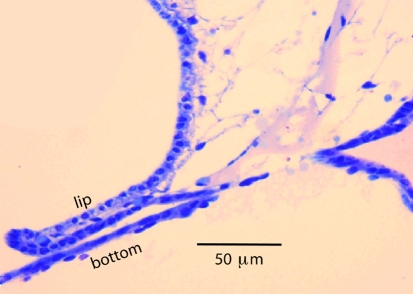
In the 3D OPFOS-reconstruction of the entrance of Bast’s valve, shown in Fig. 3, the lip of the valve appears as a relatively rigid structure. In a comparable scanning electron microscopy (SEM) image the entrance of the valve is visible as a narrow slit in the utricular wall [9]. The valve lip is filled with connective tissue (Fig. 2c). This is even better visible in Fig. 6, which is a light microscopy (LM) image. This figure also clearly shows that the bottom of the valve has a thickness of only one cell-layer, and is as result highly compliant.
Fig. 6.
Light microscopy image of lip and bottom of Bast’s valve
Schuknecht and Belal [13] showed that the corium of the valve consists of fibroblasts and fibrocytes.
Based on the study of 170 human temporal bones these authors propose that the valve is closed in normal ears and that its anatomical structure is ideally suited to permit the occasional egress of excessive accumulation of endolymph to be processed in the endolymphatic sac, while preventing an excessive loss of endolymph with the possible consequence of membrane distortions and interference with the motion mechanics of the vestibular sense organs. Opening of the valve, still according to Schuknecht and Belal [13], would then be accomplished by pressure displacement of the outer membraneous wall away from the more rigid inner valve lip.
The arrows in Fig. 2c indicate positions were the valve appears to be closed. Also in Fig. 6 valve lip and bottom touch.
Bast himself [5] was not sure about the valve being opened or closed in the normal situation. He writes: “As a matter of fact in many histological sections the epithelium of the valve is in contact with the opposing wall of the slit-like opening of the duct which suggests that such a closure may exist, at least at times, in the living ear.”
He also was not certain about the mechanism that closes the valve [5].
On the one hand he supposed that a high perilymphatic pressure could close the valve by moving the opposing wall against the valve lip, as shown in Fig. 7. On the other hand he proposed closing of the valve lip against the opposing duct wall in the case of a relatively greater intra-utricular pressure. In this case he supposes that it is not the tip of the valve that moves, because it is bulky, but that the valve lip rotates at its base, where it is made up of loose perilymphatic tissue.
Fig. 7.
Possible mechanism of valve closure (black arrows) or valve opening (grey arrows)
In our opinion the latter mechanism is less likely, considering the observation that the valve opening in 3-D reconstruction is a rigid arch-like structure (Fig. 3), and not a flap hinged at its base, that could close an underlying opening. The latter mechanism may be inspired by 2-D pictures, like Fig. 2b, c and 6, where the valve tip appears as a flap-like structure.
The rigidity of the valve tip was also noticed by Scheerer and Hildmann [12], who also thought it to be improbable that this structure can function as a valve.
The walls of the endolymph filled spaces in the inner are highly compliant. As a result the pressure difference between endolymph and perilymph are negligible in the normal situation [19]. If the valve is open it seems, at first impression, easy to understand how an increase of perilymphatic pressure will close the valve by compression of its bottom, as is shown in Fig. 7. However, an increasing perilymphatic pressure will also increase the endolymphatic pressure inside the utricule and force endolymph out through the slit-like opening and prevent closure of the valve [11, 18].
As can be seen in Figs. 4 and 5 the utricular duct has a diameter in the order of 10 μm at its narrowest passage, preventing rapid flow of endolymph and possibly protecting the sensitive vestibular receptors against large fluid shifts in a short time.
Konishi [8] found an open utriculo-endolymphatic valve in guinea pigs with an (experimental) endolymphatic hydrops. It is conceivable that an excess of endolymph will force the base of the valve opening away from the lip, as shown in Fig. 7.
In future work, high-resolution OPFOS (HROPFOS) with slicing, a resolution of 2 μm [6] is feasible and may reveal even more detail.
Conclusion
The use of OPFOS imaging techniques and graphical 3D-reconstruction of the uticulo-endolymphatic (Bast’s) valve and its surroundings has given some additional insight in its functioning. It is most likely that opening or closure of the valve occurs through movement of the flexible base away from or toward the relatively rigid valve lip.
Acknowledgements
This study was supported by the Hensius Houbolt Foundation and is part of the research program of our department: communication through hearing and speech. The program is incorporated in the Sensory Systems Group of the Groningen Graduate School for Behavioral and Cognitive Neuroscience.
Contributor Information
R. Hofman, Phone: +31-50-3612540, FAX: +31-50-3611698, Email: r.hofman@kno.umcg.nl
J. M. Segenhout, Email: j.h.segenhout@kno.umcg.nl
J. A. N. Buytaert, Email: jan.buytaert@ua.ac.be
J. J. J. Dirckx, Email: joris.dirckx@ua.ac.be
H. P. Wit, Email: h.p.wit@med.umcg.nl
References
- 1.Anson BJ, Black WT (1934) The early relation of the auditory vesicle to the ectoderm in human embryos. Anat Rec 58:127–137 [DOI]
- 2.Bachor E, Karmody CS (1995) The utriculo-endolymphatic valve in paediatric temporal bones. Eur Arch Otorhinolaryngol 252(3):167–171 [DOI] [PubMed]
- 3.Bast TH (1928) The utriculo-endolymphatic valve. Anat Rec 40(1):61–65 [DOI]
- 4.Bast TH (1934) Function of the utriculo-endolymphatic valve. Two cases of ruptured saccules in children. Arch Otolaryngol 19:537–550
- 5.Bast TH (1937) The utriculo-endolymphatic valve and duct and its relation to the endolymphatic and saccular ducts in man and guinea pig. Anat Rec 68(1):75–93 [DOI]
- 6.Buytaert JAN, Dirckx JJJ (2007) Design and quantitative resolution measurements of an optical virtual sectioning three-dimensional imaging technique for biomedical specimens, featuring two-micrometer slicing resolution. J Biomed Opt 12(1):014039 [DOI] [PubMed]
- 7.Hofman R, Segenhout JM, Albers FWJ, Wit HP (2005) The relationship of the round window membrane to the cochlear aqueduct shown in three-dimensional imaging. Hear Res 209(1–2):19–23 [DOI] [PubMed]
- 8.Konishi S (1977) The ductus reunions and utriculo-endolymphatic valve in presence of endolymphatic hydrops in guinea pigs. J Laryngol Otol 91:1033–1045 [DOI] [PubMed]
- 9.Lim DJ (1991) Scanning electron microscopic morphology of the ear. In: Paparella MM, Gluckman JL, Meyerhoff WL (eds) Otolaryngology, 3rd edn. Saunders
- 10.Pearlman HB, Lindsay JR (1936) The utriculo-endolymphatic valve. Arch Otolaryngol 24:68–74
- 11.Salt AN (2007) The endolymphatic sinus is a possible detector of endolymph volume status. Hear Res 224:117–118 [DOI] [PMC free article] [PubMed]
- 12.Scheerer WD, Hildmann H (1979) Vergleichende Untersuchungen über den Ductus und Saccus endolymphaticus em embryonalen Schädel. Arch Otolaryngol 222:175–180 [DOI] [PubMed]
- 13.Schuknecht HF, Belal AA (1975) The utriculo-endolymphatic valve: its functional significance. J Laryngol Otol 89:985–996 [DOI] [PubMed]
- 14.Spalteholz W (1914) Ueber das Durchsichtigmachen von Menschlichen und Tierischen Preparaten. S. Hirzel, Leipzig
- 15.Voie AH (2002) Imaging the intact guinea pig tympanic bulla by orthogonal-plane fluorescence optical sectioning microscopy. Hear Res 171(1–2):119–128 [DOI] [PubMed]
- 16.Voie AH, Burns DH, Spelman FA (1993) Orthogonal-plane fluorescence optical sectioning: three-dimensional imaging of macroscopic biological specimens. J Microsc 170(Pt 3):229–236 [DOI] [PubMed]
- 17.Voie AH, Spelman FA (1995) Three-dimensional reconstruction of the cochlea from two-dimensional images of optical sections. Comput Med Imaging Graph 19(5):377–384 [DOI] [PubMed]
- 18.Wit HP, Hofman R (2007) Does the endolymphatic sinus function as a one-way valve? Hear Res 224:115–116 [DOI] [PubMed]
- 19.Wit HP, Warmerdam TJ, Albers FWJ (2000) Measurement of the mechanical compliance of the endolymphatic compartments in guinea pig. Hear Res 145:82–90 [DOI] [PubMed]
- 20.Zechner G (1980) Innenohrhydrops als Folge gestörter Endolymphzirkulation. Laryngol Rhinol Otol 59:829–833 [PubMed]


