Abstract
We propose in this paper a new method for the mapping of hippocampal (HC) surfaces to establish correspondences between points on HC surfaces and enable localized HC shape analysis. A novel geometric feature, the intrinsic shape context, is defined to capture the global characteristics of the HC shapes. Based on this intrinsic feature, an automatic algorithm is developed to detect a set of landmark curves that are stable across population. The direct map between a source and target HC surface is then solved as the minimizer of a harmonic energy function defined on the source surface with landmark constraints. For numerical solutions, we compute the map with the approach of solving partial differential equations on implicit surfaces. The direct mapping method has the following properties: 1) it has the advantage of being automatic; 2) it is invariant to the pose of HC shapes. In our experiments, we apply the direct mapping method to study temporal changes of HC asymmetry in Alzheimer disease (AD) using HC surfaces from 12 AD patients and 14 normal controls. Our results show that the AD group has a different trend in temporal changes of HC asymmetry than the group of normal controls. We also demonstrate the flexibility of the direct mapping method by applying it to construct spherical maps of HC surfaces. Spherical harmonics (SPHARM) analysis is then applied and it confirms our results about temporal changes of HC asymmetry in AD.
Keywords: Hippocampal surface, intrinsic shape context, direct mapping, shape analysis, implicit representation, level set, temporal changes, asymmetry, Alzheimer disease
1 Introduction
The hippocampus is a subcortical structure that plays an important part in learning and memory in normal development and is affected by pathologies such as Alzheimer disease (AD), schizophrenia, and epilepsy (Squire et al., 2004). While the detection of hippocampal (HC) volume changes has been the focus of most image processing studies because of its relatively straightforward interpretation, the popularity of more sophisticated approaches based on shape analysis is increasing as they promise more accurate localization of changes in HC surfaces. In this paper, we propose a novel method for the analysis of HC surfaces that establishes a direct map between HC surfaces.
For the analysis of HC surfaces, two different approaches have been taken in previous studies. The first approach aims at finding a map between points on HC surfaces. This correspondence can then be used for further statistical analyses, for example the principal component analysis of point sets (Bookstein, 1997; Cootes et al., 1995). Various shape representations have been used to compute the map between HC surfaces. Based on the large deformation diffeomorphism method (Christensen et al., 1996; Grenander and Miller, 1998; Joshi and Miller, 2000), a map from a template HC surface embedded in a 3D MRI image to a target MRI image is computed using information from both manually labeled landmark points and the grey levels of image intensities (Joshi et al., 1997; Csernansky et al., 1998; Wang et al., 2001; Csernansky et al., 2002; Wang et al., 2003; Csernansky et al., 2005; Holm et al., 2004; Vaillant et al., 2004; Vaillant and Glaunes, 2005; Wang et al., 2006). This method can produce both an automatic segmentation of the HC surface and a map from the template HC surface to the segmented surface. Proper alignment of the template and target image volume is necessary before the transformation is computed to reduce the sensitivity with respect to the initial pose. Another popular method of HC surface mapping is based on the parameterization of the HC surface with the spherical harmonic basis functions (Brechbühler et al., 1995) which establishes correspondence between points with the resulting parameterization (Kelemen et al., 1999; Gerig et al., 2001; Shenton et al., 2002; Shen et al., 2003). The map derived from this method also depends on the initial alignment of HC surfaces. A triangulation approach (MacDonald, 1998) was utilized to represent HC surfaces (Lee et al., 2004), where homologous points between surfaces were found with a distance map to the centroid of each surface after initial alignment. Recently conformal parameterizations were used to study HC surfaces (Wang et al., 2005a,b) by matching the mutual information between the mean curvature of surfaces in the parameterization domain.
The second approach uses the medial models of HC surfaces to perform shape analysis. As a direct extension of the medial axis in 2D shapes (Golland et al., 1999), a center line of the HC surface was used as a simple and compact representation to compare 3D shapes (Thompson et al., 2004; Narr et al., 2004). Based on the mathematical definition of medial models (Blum and Nagel, 1978), the medial model of a 3D surface is a set of manifolds. For a group of HC surfaces, the challenge is that their medial models may not have the same topology because of their sensitivity to small variations on surfaces. To overcome this difficulty, a fixed topology has been imposed for the medial models of HC surfaces in many previous works (Pizer et al., 1999; Styner et al., 2003; Fletcher et al., 2004; Bouix et al., 2005). Due to the variability of HC surfaces, however, there is no consensus on the topology of the medial model to perfectly represent the HC surface. A careful balance must be found between the robustness and complexity of the medial models.
In this paper, a new method is presented to compute maps between HC surfaces based on an intrinsic characterization of HC geometry using a new feature called the intrinsic shape context (ISC). This feature captures the global characteristics of HC surfaces and provides a quantitative approach to describe our anatomical intuition that different parts of the hippocampus can be located using their relative positions on the surface, irrespective of the pose of the shape. Such global characterizations are also more stable to the impact of disease processes on HC geometry than local curvature features. This makes them suitable to guide the mapping and comparison of both HC surfaces of normal controls and those affected by diseases such as AD. Based on the ISC feature, we develop an automatic method to detect a set of robust landmark curves and use them as boundary conditions to compute the direct map between surfaces. This direct map represents the minimizer of a harmonic energy defined on the HC surface under landmark constraints. We compute the map directly without intermediate parameterizations by solving a partial differential equation (PDE) on the HC surface with the implicit representation (Osher and Sethian, 1988). Our method is completely automatic and invariant to rigid body motions and scaling, which eliminates initial alignment using the rigid transform before computing the map, a necessary step in many previous algorithms. Using the level-set representation, we can use numerical schemes on regular grids to compute intrinsic gradient operators for the solution of the PDE on the HC surface.
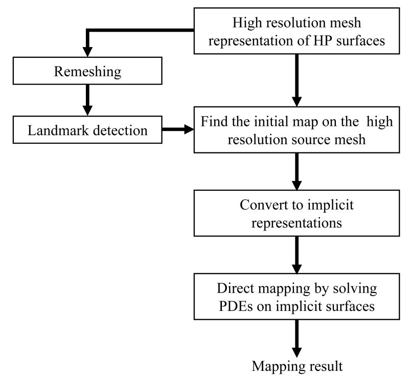
As an illustration, the main steps of the whole mapping process between two HC surfaces using our algorithm are summarized as a flowchart in Fig. 1. The input data are the triangular mesh representation of the source and target HC surface. Here they are denoted as high resolution meshes to contrast with meshes of lower resolution used in landmark detection. These high resolution meshes are then remeshed to 1000 vertices. The result of the remeshing process generates a good approximation to the original surface but tractable for landmark detection using the ISC feature. Using our automatic landmark detection algorithm, a set of landmark curves on both the source and target surface are then generated and used as the boundary condition for computing the map between them. Using the landmark curves, an initial map from the source to the target HC surface is computed on the original high resolution source HC surface (Shi et al., 2007). After that, both the high resolution meshes and the initial map are converted to their implicit representations and a PDE is solved iteratively in a narrowband of the implicitly represented surfaces to minimize the harmonic energy under landmark constraints (Shi et al., 2007). The solution of the direct mapping method is a map from the source to the target HC surface defined in a narrowband of the source surface and interpolation can be used to obtain the value of the map on vertices of the mesh representation for visualization or other purposes.
Fig. 1.
The flow chart of the whole mapping process.
The rest of the paper is organized as follows. The general framework of direct mapping between surfaces under landmark constraints is first reviewed. After that, we present the definition of the ISC feature and discuss its numerical computation. Using the ISC feature, we develop an automatic algorithm to delineate a set of landmark curves to provide the boundary condition for mapping between surfaces. Once the whole mapping framework is presented, we show its application in HC atlas construction, measuring HC asymmetry and performing spherical harmonic analysis of HC surfaces. Experimental results are presented to demonstrate the usefulness of our method with the construction of a HC atlas and the analysis of HC asymmetry changes that occur during the progression of AD. Finally, we discuss the relation of our method to previous works and suggest future directions for research.
2 Method
2.1 The Direct Mapping Framework
A direct mapping framework for cortical surfaces with sulcal landmark constraints was proposed by solving PDEs on implicitly represented surfaces (Shi et al., 2007). Even though this method was presented in the context of cortical mapping, the method by itself is general and can be applied to the mapping of surfaces derived from other objects as long as stable landmark curves may be extracted on the surfaces of interest. In this section, the mathematical background of this direct mapping framework is discussed, followed by its extension to the mapping of HC surfaces.
Let M and N denote the source and target surface and the goal is to compute a map . For each surface, assume that a set of landmark curves are provided and the map on them is known. Let denote the set of landmark curves on M and the landmark curves on N. The implicit representations of the surfaces and the map are used in this direct mapping approach (Osher and Sethian, 1988; Bertalmío et al., 2001; Mémoli et al., 2004a,b). For the surface M, it is represented implicitly as the zero level set of its signed distance function . Because the signed distance function has the property |∇φ| = 1, we have the simple form for the projection operator Π∇φ onto the tangent space of M, where I is the identity operator. Similarly the signed distance function ψ of N is used to represent it implicitly. With implicit representations, all numerical computations are performed on regular grids, which leads to algorithms that are easy to implement and have well-understood numerical performance. Consistent with the implicit representation of the surface, the map u defined on M is also extended along the normal direction of M into the surrounding Euclidean space such that Ju∇φ = 0, where Ju is the Jacobian of u. Based on the implicit representations of the surfaces and the map, the direct mapping framework explained here solves the map as the minimizer of the following constrained variational problem:
| (1) |
where is the intrinsic Jacobian of u on the manifold M, the matrix norm of is the Frobenius norm defined as , and δ(·) is the delta function. The constraints in the above formulation are the boundary conditions on landmark curves. By minimizing the harmonic energy while satisfying the landmark constraints, the map obtained will interpolate the boundary conditions as smoothly as possible.
If we ignore the constraints on the landmark curves, a gradient descent type algorithm has been proposed (Mémoli et al., 2004a) to solve for the map u iteratively according to the Euler-Lagrange equation of the harmonic energy:
| (2) |
where is the projection operator onto the tangent space of N at the point u(x, t). To take into account the landmark constraints, we first developed a novel algorithm to compute an initial map between surfaces using the relative location of points on surfaces with respect to the landmark curves that was summarized with a feature called landmark context. Adaptive numerical schemes were then designed to compute the operator such that diffusion is only allowed in between landmark curves but not across them on the surface M. Cortical mapping experiments have demonstrated that our method can successfully minimize the energy while following the constraints on sulcal landmark curves (Shi et al., 2007).
The goal in this paper is to extend the direct mapping method to HC surfaces. By establishing direct maps between HC surfaces, properties on HC surfaces will be better localized, providing a new tool for neuroscience researchers. Unlike cortical surfaces, however, there is no obvious landmark curve on HC surfaces. To overcome this challenge, we next propose the ISC feature on surface using their intrinsic geometry. Based on this feature, we then develop an automatic algorithm that delineates a set of stable landmark curves on HC surfaces. After that, the direct mapping framework in Eq. (1) may be applied to compute maps between HC surfaces.
2.2 Intrinsic Shape Context
Landmark curves are critical for the mapping of surfaces because they encode high level information and make the final mapping meaningful. Previous approaches on the automatic detection of landmark curves on anatomical shapes typically focused on extremities of local features, such as curvature (Thirion, 1996; Lui et al., 2006). One advantage of such features is that they are invariant to rigid motions. However, in our experience these features tend to be noisy and lack robustness, and it is generally difficult to establish correspondences for landmark curves derived from such local features on different shapes without human intervention. For shapes like HC surfaces, this type of approach is difficult to apply since there is no obvious geometric extremity.
Our research takes a different route and proposes a global shape feature called the intrinsic shape context (ISC) to detect landmark curves in our direct mapping of HC surfaces. The ISC feature we propose here is motivated by the shape context feature (Belongie et al., 2002) that can be used to capture global characteristics of the shape (Tu and Yuille, 2004). Another closely related work is the spin image feature (Johnson and Hebert, 1999) for the characterization of 3D shapes represented as meshes. The major distinction between our method and previous works is that we define the ISC feature using only the intrinsic geometry of the surface. With the ISC feature, each point on the HC surface is characterized by its relative location to other parts of the hippocampus. This characterization is invariant to scale and rigid transforms. The idea of intrinsic shape context matches well with our anatomical intuition of the hippocampus because its parts, such as the head, tail and body, are also characterized through their relative locations on the hippocampus and can typically be differentiated with respect to each other no matter how we change the pose of the hippocampus. By utilizing landmark curves derived from the ISC feature, we can capture this anatomical regularity and establish correspondences between individual surfaces through the direct mapping process.
2.2.1 Definition of ISC
Let M denote a HC surface which has genus zero topology. For two points p and q on M, let be a curve on the surface that connects p and q. The length of the curve is defined as
| (3) |
where the magnitude of the tangent vector C′(t) is determined by the first fundamental form of the Riemannian surface M, which is the inner product of tangent vectors. For all the curves from p to q, the one of the minimum length is called the minimal geodesic. The length of the minimal geodesic from p to q is called the geodesic distance between these two points and it is denoted as d(p, q). The geodesic distance between any two points on M is independent of the ambient space where the surface is embedded and is thus intrinsic to the surface. Based on the concept of geodesics, the geodesic distance transform of a point p on the manifold M can be defined as:
| (4) |
We also denote the maximum distance between two arbitrary points on M as dmax, i.e.,
| (5) |
To illustrate the advantage of using the geodesic distance for the design of pose invariant features in 3D shape analysis (Elad and Kimmel, 2003; Ben Hamza and Krim, 2006), instead of the Euclidean distance, we consider a “C” shape formed by cutting open a torus. With geodesic distances, it is easy to identify both ends of this shape as their geodesic distance transforms achieve the largest value, while they are almost not distinguishable from the rest of the shape using the Euclidean distance.
To define the ISC feature at a point p on M, we partition the 3D shape into an ordered set of bins according to the geodesic distance transform dp(·). Let K denote the number of bins and the bin size be defined as ∊ = dmax/K. A set of K bins on M with respect to a point p ∈ M is defined as follows:
| (6) |
where the k-th bin, BIN(k), is the set of points with their geodesic distance to p falling into the range [k∊, (k+1)∊). Using this set of bins, the ISC feature at the point p is defined as a histogram hp(k):
| (7) |
where is the surface area of the k-th bin, and SM is the total surface area of M.
For each point on the surface, its ISC feature uses a histogram to characterize the distribution of the rest of the shape with respect to itself. The power of this feature is illustrated in Fig. 2 where the ISC of six points on a HC surface, labeled as red dots, are plotted, and each of them has a different profile. The differences between points in the middle part and end parts of the HC surface are particularly significant. The ISC features of points in the middle of the HC surface have smaller variances and tend to be more concentrated than the ISC features of points in the head and tail of the HC surface. This is easy to understand since they are closer to all the other points on the surface.
Fig. 2.
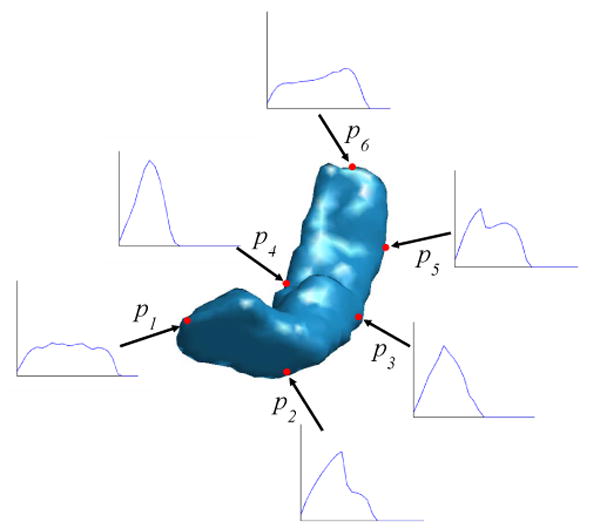
An illustration of the ISC feature of a HC shape. The ISC feature of six points p1, p2, …, p6 (labeled as red dots) on the surface are plotted.
Since only intrinsic geometry is used in its definition, the ISC feature is invariant to rigid body motions, including rotation, translation, and reflection, as such motions will not affect geodesic distances and the surface area. The ISC feature is also scale invariant. Consider a point p ∈ M and the ISC feature hp(k)(0 ≤ k ≤ K − 1) at this point. If we scale the shape M by a factor of , any point q that was in the k-th bin of p before scaling will still be in the same bin as the geodesic distance between arbitrary points, the maximum distance dmax, and the bin size ∊ will all be scaled by the same factor α. This shows that each bin of p still consists of the same set of points in M. Thus the area of each bin is scaled with the same factor α2 as the total surface area SM, which guarantees the scale invariance of the ISC feature. As a conclusion, the ISC feature is invariant to both rigid motions and scaling, which we summarize as the pose invariant property of the ISC feature.
2.2.2 Numerical Computation
The key step to numerically compute the ISC feature is to find the geodesic distance transform on a surface. For this purpose, a triangular mesh representation M = (V, T) of a HC surface is used, where V is the set of vertices, and T is the set of triangles.
To compute the geodesic distance transform of a vertex p ∈ V, we use the fast marching algorithm on triangular meshes (Kimmel and Sethian, 1998). This algorithm solves the following Eikonal equation
| (8) |
where is the intrinsic gradient of the function d on M, and is a weight function defined on the manifold. When F = 1, the solution is the geodesic distance transform. By changing F, we can get weighted geodesic distance transforms. To compute the geodesic distance transform with respect to a vertex p, the fast marching algorithm starts a front from p and recursively computes the time when the front visits each point of M. For a triangular mesh of N vertices, the computational cost is O(N logN). Using the result of the fast marching algorithm, the minimal geodesic between two vertices can also be traced backwards and computed numerically (Kimmel and Sethian, 1998). The maximum distance dmax is obtained by computing the distance transform at each vertex of the mesh M. After the geodesic distance transform dp(·) is computed, the ISC feature at p is computed by visiting each triangle and adding its contribution, which is described in the appendix, to each integral in the definition of the ISC feature hp(k).
The computational cost of finding ISC features for a mesh is directly related to the size of the mesh. To compute the ISC feature for all vertices of the mesh M, the fast marching algorithm needs to be applied N times. Including the cost of computing the histogram, finding ISC for a mesh with a large number of vertices can be computationally quite expensive. In our mapping framework shown in Fig. 1, a key step is the remeshing of the original triangular mesh representation of the HC surface to reduce the number of vertices and make the computation of the ISC feature tractable. As an example, we illustrate in Fig. 3 the effect of remeshing. The original HC surface with 27668 vertices and 55332 faces is shown in Fig. 3(a). We apply a remeshing algorithm (Peyré and Cohen, 2006) to derive a mesh with 1000 vertices and 1996 faces in Fig. 3(b). The vertices of the lower resolution mesh distribute uniformly over the high resolution mesh, and it approximates the original surface fairly well. For this lower resolution mesh, the ISC feature of all vertices can be computed in around one minute on a 3GHz PC. All of our computations for ISC features and landmark curve detection are performed on these lower resolution meshes. This ensures that our algorithm is computationally tractable and generates fairly accurate landmark curves for the original high resolution meshes.
Fig. 3.
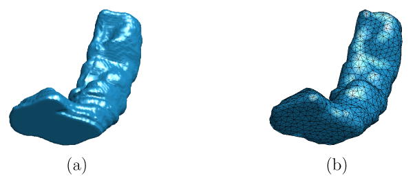
The result of remeshing. (a) A HC surface represented with a high resolution mesh (27668 vertices, 55332 faces). (b) The HC surface represented with a mesh of lower resolution after remeshing (1000 vertices, 1996 faces).
2.3 Automatic Detection of Landmark Curves
In this section, we present an automatic landmark detection algorithm using the ISC feature. As a first step in this algorithm, the HC surface is automatically partitioned into five regions with two marking the head, two marking the tail, and one marking the middle body of the HC surface. Based on this partition, a set of eight landmark curves are derived.
2.3.1 Partition of the HC Surface
As we illustrated in Fig. 2, the ISC features of different parts of the HC surface have distinctive profiles. To differentiate these parts, we use the entropy of the ISC feature as a compact summary of this very rich feature and then apply simple thresholding to get a robust partition of the HC surface.
For a vertex p ∈ M, the entropy of its ISC hp is defined as:
| (9) |
From information theory, it is well known that entropy is a good measure of the variability in a histogram and it computes how much information the histogram contains. For points on the tail or the head, we see in Fig. 2 their ISC features tend to be more uniformly distributed than those of points in the middle part of the HC surface. The entropy encodes this type of profile and assigns higher value for the head and tail part than the middle part of the HC surface, and it changes continuously as we move along the surface. For the same HC in Fig. 2, the entropy is computed at each vertex and visualized in Fig. 4(a). The map of entropy shows how the magnitude of the entropy varies at different parts of the HC surface. We denote this map as the intrinsic entropy map (IEM) of the HC surface.
Fig. 4.
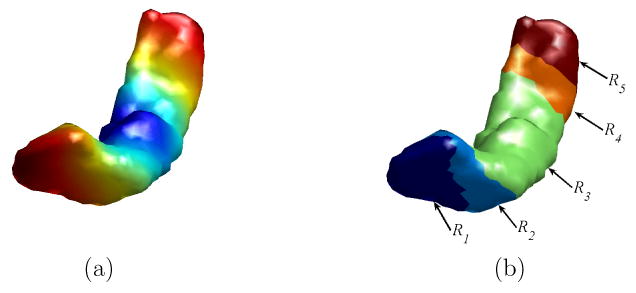
The partition of a HC surface using its intrinsic entropy map. (a) The intrinsic entropy map of the HC surface. (b) The HC surface is partitioned into five regions.
Given the IEM of the HC surface, it can then be automatically partitioned into regions with similar entropy values using simple thresholding. Let TH1 and TH2 be the median and 75 percentile of the intrinsic entropy map on M. Using these two thresholds, the HC surface can be automatically divided into 5 regions as shown in Fig. 4(b):
R1: vertices in the hippocampus head with ε(p) > TH2.
R2: vertices in the hippocampus head with TH1 ≤ ε(p) ≤ TH2.
R3: vertices with ε(p) < TH1.
R4: vertices in the hippocampus tail with TH1 ≤ ε(p) ≤ TH2.
R5: vertices in the hippocampus tail with ε(p) > TH2.
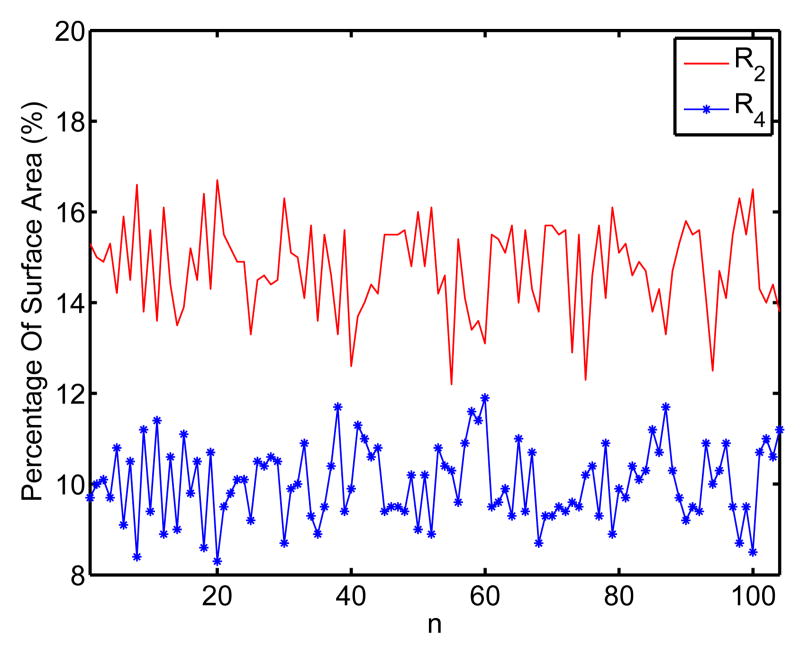
For these five regions, R1 and R2 correspond to the head, R4 and R5 correspond to the tail, and R3 corresponds to the middle body of the HC surface. The threshold TH1 is chosen such that the area of R3 is half of the total area of the HC surface. The head and tail of the HC surface are divided into smaller subregions to enforce more landmark constraints in the mapping process because they have higher variability than the HC body. The six labeled points p1, p2, …, p6 in Fig. 2 also illustrate differences of the ISC features in the five regions, with p1 in R1, p2 in R2, p3 and p4 in R3, p5 in R4 and p6 in R5. Using this very rich feature, machine learning techniques can also be adopted to automatically learn the partition process if training data are available. Even though the same range of entropy is used to define the regions in the head and tail part of the HC surface, the intrinsic geometry of the HC surface enables us to differentiate them easily. Because region R2 corresponds to a region like the “neck” in the head part, it should have an area bigger than R4. Indeed this is a very robust indicator as we found in our experiments. In Fig. 5 we plot the percentage of these two regions with respect to the total surface area for a group of 104 HC surfaces used in our experiments. These surfaces were manually segmented from the MRI images of subjects including 12 AD patients and 14 normal controls. It clearly shows that R2 is always bigger than R4. Using this feature, region R2 and R4 can be first identified from the two regions that satisfy TH1 ≤ ε(p) ≤ TH2. Once this is done, region R1 and R5 can be found using their neighboring relation with R2 and R4. As the 104 surfaces were from both AD patients and normal controls, the result in Fig. 5 also shows the robustness of our partition process. Note that the partition process is a clustering or segmentation process. The method proposed here is simple to implement and gives robust performance in our experiments. It is by no means the only way to partition the HC surface using ISC. There are various measures for the distance between histograms such as Kullback-Leibler divergence. The literature on clustering and segmentation is also vast. This promises many interesting ways of partitioning the HC surfaces.
Fig. 5.
The relative size of region R2 and R4 for a group of 104 HC surfaces.
2.3.2 Automatic Delineation of Landmark Curves
We detect eight landmark curves automatically on HC surfaces. These landmark curves can be classified into two categories: four latitudinal (C1, C2, C3, C4) and four longitudinal (C5, C6, C7, C8) landmark curves. The latitudinal curves are the boundary of the five regions R1, R2, R3, R4 and R5 as a result of the partition process using the IEM. The longitudinal curves travel from the head to the tail and connect the region boundaries of R1 and R5.
The latitudinal landmark curve Ci(1 ≤ i ≤ 4) is the boundary between region Ri and Ri+1 on the triangular mesh M as shown in Fig. 6. For each curve Ci, we define it as a piecewise linear curve that sequentially connects the set of vertices in Ri with at least one vertex in its 1-ring neighborhood that belongs to Ri+1. Starting from an arbitrary vertex on Ci, it can be traced along either clockwise or counterclockwise to delineate a closed contour. Maintaining a consistent tracing order is critical in establishing correspondences on the landmark curves of different HC surfaces during the mapping process. In this research, the order of the curves is chosen with respect to the region R1, which is the head of the HC surface. For the left HC surface, the region boundaries are traced clockwise with respect to R1. Due to the reflective relation between the right and left HC, the boundaries are traced counterclockwise with respect to R1 on the right HC surface.
Fig. 6.
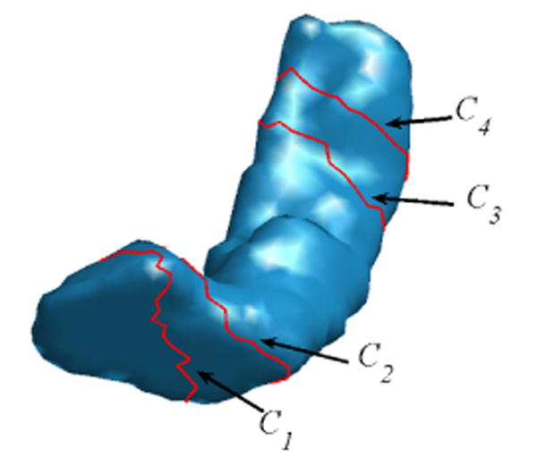
Latitudinal landmark curves (in red) on a HC surface.
The longitudinal landmark curves connect C1 to C4 and partition the region R2 ∪ R3 ∪ R4 into four parts. For the automatic delineation of these curves, we first choose a region Rc = {p ∈ M|ε(p) < TH3}, where TH3 is the 25 percentile of the IEM, and compute its geodesic center p* as the minimizer of the following energy function:
| (10) |
where dp is the geodesic distance transform of the point p. The existence and uniqueness of such a minimizer is ensured for smooth Riemannian manifolds (Jost, 2001). As a result of remeshing, the number of vertices in Rc is limited, so a full search strategy within Rc can be used to find p*. A gradient descent type algorithm was also proposed to find p* on surfaces (Peyré and Cohen, 2004). Because of the trend of bending from the head of the HC surface to its tail, which can be seen from the more concentrated ISC feature of p4 than that of p3 in Fig. 2, the region Rc and the starting point p* localize stably on the side of HC surface close to the medial wall of cortical surface. Using p* as the starting point, we next describe the process of delineating C5, C6, C7 and C8 as illustrated in Fig. 7(a), (b), (c) and (d).
Fig. 7.
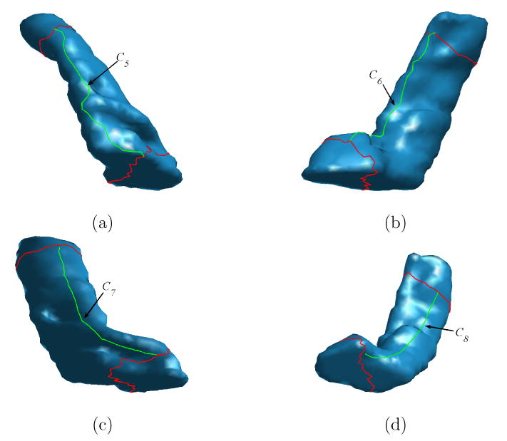
The delineation of longitudinal landmark curves (in green) on a HC surface. (a) C5. (b) C6. (c) C7. (d) C8.
-
The delineation of C5
We first compute the geodesic distance transform dp* of p* on M. The start point p1,5 of C5 is the farthest point on C1 to p*. The end point p4,5 of the curve C5 is the farthest point on C4 to p*. The curve C5 connects these two points using a weighted geodesic on M with the weight defined as F = 1/(dp* + 10−6). This weight penalizes points close to the starting point p* and ensures that the curve C5 will follow a path on the lateral side of the HC surface that is away from the medial wall of the cortical surface.
-
The delineation of C6
The landmark curve C6 will be on the medial side of the HC surface and it runs approximately parallel to C5. For this purpose, we compute the geodesic distance transform dC5 with respect to the curve C5, and choose the start point p1,6 of C6 as the farthest point on C1 to C5 and the end point of C6 as the farthest point on C4 to C5. The curve C6 is then formed by connecting both the start and end point to p* through a weighted geodesic on M with the weight defined as F = 1/(dC5 + 10−6) such that points close to the lateral side on the surface will be penalized more. This encourages the curve C6 to follow a path on the medial side of the HC surface close to the medial wall of the cortical surface.
-
The delineation of C7 and C8
The curves C7 and C8 further divide the closed regions formed by the curves C1, C4, C5 and C6. The start point of C7 is the middle point of the curve that traces from p1,6 to p1,5 on C1, and the start point of C8 is the middle point of the curve that traces from p1,5 to p1,6 on C1. The end point of C7 is the middle point of the curve that connects p4,6 to p4,5 and the end point of C8 is the middle point of the curve that connects p4,5 to p4,6. The end points of both C7 and C8 is then connected to their start points through a weighted geodesic on M with the weight defined as F = 1/(dC5 + dC6) such that points close to C5 and C6 are penalized more and the curves C7 and C8 will divide the regions between C5 and C6 equally.
Up to now, we have developed an automatic algorithm to detect a set of eight landmark curves on HC surfaces. Because the landmark curves are derived from the ISC feature, they also have the property of pose invariance. We applied it to a data set of 104 HC surfaces that were used in our experiments and were able to detect these curves on all of them. Even though it is hard to quantify the stability of landmark curves on different HC surfaces, the ISC feature ensures these landmark curves are robust to small changes of surface geometry because it is defined using geodesic distances that are robust to local variations of surfaces. As an example, the left HC surfaces from the baseline and follow-up scan of an AD patient are shown in Fig. 8, together with the automatically detected landmark curves. We can see various changes happen to the HC surface from the follow-up scan, as highlighted with black arrows in Fig. 8(b), but the relative locations of the landmark curves remain quite stable. This suggests that these landmark curves can provide valuable guidance to the registration process and help establish mappings between corresponding parts of HC surfaces.
Fig. 8.
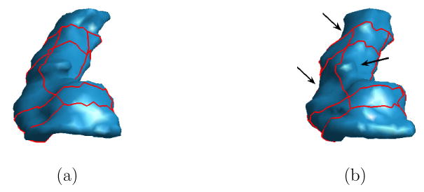
Stability of landmark curves on HC surfaces from an AD patient at (a) the baseline scan, and (b) the follow-up scan. Arrows in (b) highlight shape differences.
To apply the landmark curves into our direct mapping algorithm, we further divide the eight curves into line segments using the intersection of the landmark curves. For the latitudinal curves, each of them is divided into four segments using their intersections with the longitudinal curves. For the longitudinal curves, each of them is divided into three parts according to their intersections with latitudinal curves. Overall, we have 28 landmark curves on each HC surface. By parameterizing them using curve length, one to one correspondence can be established between points on landmark curves from different HC surfaces. This defines the map on the landmark curves and forms the boundary condition for the direct mapping of HC surfaces.
2.4 HC Atlas Construction
Given a group of HC surfaces M1,M2, …,MQ, we can construct a HC atlas with our direct mapping method. We choose an arbitrary surface as the source surface and compute the direct maps from this surface to the rest of surfaces in the group. Without loss of generality, we use M1 as the source surface here and denote the maps from M1 to Mq as uq(q = 2, …,Q). Let Vi(i = 1, …,N) be the set of vertices on M1. We project each vertex Vi onto Mq with the direct map uq and express the corresponding point as uq(Vi). Using these correspondences, a rigid transform Tq including rotation and translation is computed to align each surface Mq(q = 2,…,Q) with M1 by minimizing the following energy:
| (11) |
This optimization problem is solved with the dual quaternion method (Walker et al., 1991) that provides the closed form solution to the matching of point pairs. The mean of the vertex Vi with its corresponding points uq(Vi) on Mq(q = 2,…,Q) is computed as (Cootes et al., 1995):
| (12) |
and the atlas surface is represented as a triangular mesh with the vertices and the same mesh structure as M1. With an increase of computational cost, an iterative strategy (Cootes et al., 1995) can also be used to further reduce the bias in the HC atlas by repeating the above procedure with the current atlas as the source surface.
2.5 Mapping HC Asymmetry
By computing a direct map from the left to the right HC surface from the same subject, we can easily calculate an asymmetry measure between them. Let ML and MR denote the triangular mesh representation of the left and right HC surface and the map between them. Let be the set of vertices on ML. The projection of the vertices onto MR are . Before we measure the asymmetry, we compute a rigid transform T to align ML and MR similar to the aligning process in the atlas construction process. Using the map u and the rigid transform T, a measure of local asymmetry at each point p on the left HC surface is defined as:
| (13) |
This measure characterizes the magnitude of the difference between each point p ∈ ML and its image u(p) ∈ ML after we factor out the rigid transform T. By integrating the local asymmetry Lasym over the left HC surface, we can then define a global asymmetry measure Gasym between the left and right HC surface. Numerically we can compute Gasym over the triangular mesh ML as follows:
| (14) |
where T is the set of triangular faces of ML, are the vertices of the i-th face Ti of ML, and is the local asymmetry at a vertex. The asymmetry over each face is approximated as the product of its area and the mean of the local asymmetry of its vertices. The global asymmetry is then the sum of the asymmetry over all faces.
2.6 Spherical Harmonics Analysis of HC Surfaces
Spherical harmonic (SPHARM) analysis has been an important tool for studying HC surfaces and other brain structures. The key step in applying SPHARM analysis is to map a HC surface to the sphere (Brechbühler et al., 1995). Once this map is computed, SPHARM analysis is in principle similar to Fourier analysis and it provides a mechanism to decompose surfaces into orthogonal basis functions. This makes it possible to apply conventional filtering techniques in signal processing to shape analysis, such as smoothing through low pass filtering that eliminates high frequency components. We demonstrate here that our mapping method can also be applied to construct maps from HC surfaces to the sphere and thus provide a new way of performing SPHARM analysis of HC surfaces.
Let the unit sphere be parameterized by (θ, φ) with θ ∈ [0, π] and φ ∈ [0, 2π). The north and south pole are parameterized by θ = 0 and π, respectively. To map the HC surface to the sphere, we define a similar set of landmark curves on the sphere as shown in Fig. 9. We define the four latitudinal curves C1, C2, C3, C4 on the sphere as the parallels of latitude with θ = 0.23π, 0.33π, 0.67π, 0.77π. The latitudinal angles are chosen such that the area of the region between C2 and C3 is half the area of the sphere. The curve C1 further divides the region north of C2 into two subregions of equal area. Similarly, the curve C4 divides the region south of C3 into two subregions of equal area. This process matches the selection of the thresholds TH1 and TH2 in our landmark detection algorithm on HC surfaces. The four longitudinal curves C5, C6, C7, C8 are chosen as the intersection of four meridians of azimuth φ = 0, π, π/2, 3π/4 and the region between C1 and C4. Using the landmark curves, we can then map HC surfaces to the sphere with our direct mapping algorithm.
Fig. 9.
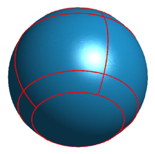
Landmark curves on the sphere.
As a result of the spherical mapping process, each point on a HC surface can be parameterized with the spherical coordinates (θ, φ) and we denote this parameterization as x(θ, φ). With spherical harmonic functions, we can then approximate the HC surface as (Brechbühler et al., 1995):
| (15) |
where is the spherical harmonic basis function indexed by (l, m), L is the maximum order of approximation, and is the expansion coefficient that equals the projection of x(θ, φ) onto :
| (16) |
Using the SPHARM analysis, a different measure of HC asymmetry can be defined. For each subject, we first align its left HC surface ML to the right HC surface MR using the direct mapping from ML to MR as we did in computing Gasym in Eq. (14). After that, the map to the sphere is computed for each surface and SPHARM analysis is applied. Let the coefficients be denoted as and for ML and MR, respectively. Our asymmetry measure based on the SPHARM representation is defined as:
| (17) |
which sums up the difference between corresponding coefficients up to the order L.
3 Results
In this section, we present experimental results to demonstrate our direct HC mapping framework. In our experiments we used HC surfaces of 26 subjects that were scanned using T1-weighted MRI on two occasions to study temporal changes of brain structures of AD patients (Thompson et al., 2004). The 26 subjects include 12 AD patients (age at baseline scans: 68.4 ± 1.9 years; at follow-up scans: 69.8±2.0 years) and 14 normal elderly controls (age at baseline scans: 71.4 ± 0.9 years; at follow-up scans: 74.0 ± 0.9 years). For the group of AD patients, the average time between the baseline and follow-up scan is 1.5 years. For the group of normal controls, the average interval between the two scans is 2.6 years. The HC surfaces were manually traced bilaterally from 3D MRI images (Thompson et al., 2004) according to a standard neuroanatomical atlas (Duvernoy, 1988), following criteria robust to inter- and intrarater errors (Narr et al., 2001, 2002a, b). To construct the triangular mesh representation of HC surfaces, we first computed the distance transform of each HC surface from its manually traced result. A fast level set algorithm (Shi and Karl, 2005) was then used to extract the zero level set of the distance function with genus zero topology. After that, we ran a marching cube algorithm with topology guarantees (Lewiner et al., 2003) to obtain the final mesh representation of HC surfaces, which were used as inputs to our direct HC mapping framework shown in Fig. 1.
3.1 Atlas Construction
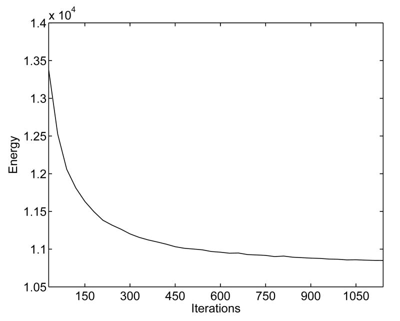
In this experiment, we demonstrate our direct mapping method through the construction of a HC atlas. As an example, we first show the mapping results between two left HC surfaces, which were chosen randomly from the baseline scans of normal controls, following the flowchart in Fig. 1. The high resolution mesh representations of the source and target HC surface are shown in Fig. 10(a) and (b). The results of the remeshing and landmark detection algorithm are shown in Fig. 10(c) and (d). Using the landmark curves and the high resolution meshes in Fig. 10(a) and (b), an initial map was then computed. To visualize this initial map, a zebra pattern on the source mesh as shown in Fig. 11(a) was generated and projected onto the target surface as shown in Fig. 11(b). Clearly, the result is quite noisy and not satisfying. After converting the surfaces and the initial map to their implicit representations, the PDE in Eq. (2) was solved iteratively to compute the direct map. This computational process took around 20 minutes on a 3GHz PC. The harmonic energy is plotted as a function of the iterations in Fig. 12, and we see that our algorithm minimized the energy and converged to the final result. As a visualization of the final map, it was used to project the zebra pattern in Fig. 11(a) onto the target surface. The result is shown in Fig. 11(c) where the pattern is well preserved on the target surface. This shows that our algorithm generates a smooth map from the source to the target surface and preserves corresponding structures during the mapping process.
Fig. 10.
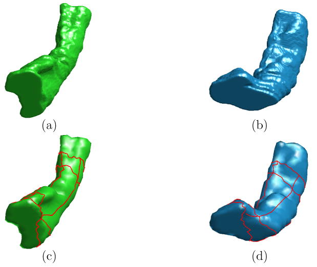
The input data to the direct mapping algorithm. (a) (b) The high resolution source and target HC surface. (c)(d) Landmark curves plotted in red on the lower resolution source and target surface from remeshing.
Fig. 11.
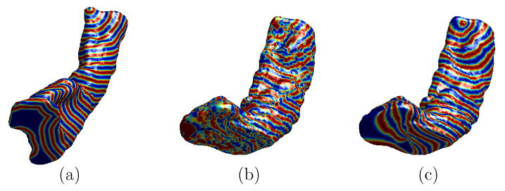
Visualization of mapping results. (a) The zebra pattern on the high resolution source surface. (b) Projection of the zebra pattern onto the high resolution target surface using the initial map. (c) Projection of the zebra pattern onto the high resolution target surface using the final map computed from minimizing the harmonic energy under landmark constraints.
Fig. 12.
The harmonic energy decreases as the direct mapping algorithm converges to the solution.
By repeating the above mapping process, we constructed a HC atlas using the 14 left HC surfaces from baseline scans of the control group. The source surface here was represented as a triangular mesh of 2000 vertices. The HC atlas, which is the average of the 14 surfaces and shares the same mesh structure of the source surface, is shown in Fig. 13 in two different views. We applied our landmark delineation algorithm to this atlas and it successfully detected the complete set of landmark curves as plotted on the atlas in Fig. 13. This validates that our direct mapping algorithm is able to establish mappings between corresponding structures of HC surfaces and generate an HC atlas that maintains the overall shape of HC surfaces. Based on this atlas, various shape analysis tasks can be performed. For example, it can be used as a reference to measure local changes of individual surfaces (Wang et al., 2003). We also used it as a substrate for visualization in our experiments of mapping HC asymmetry.
Fig. 13.
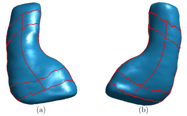
The HC atlas with automatically detected landmark curves. (a) View one from the bottom. (b) View two from the top.
3.2 Mapping Temporal Changes of HC Asymmetry
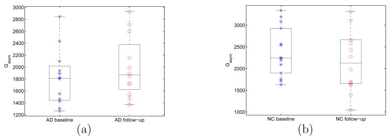
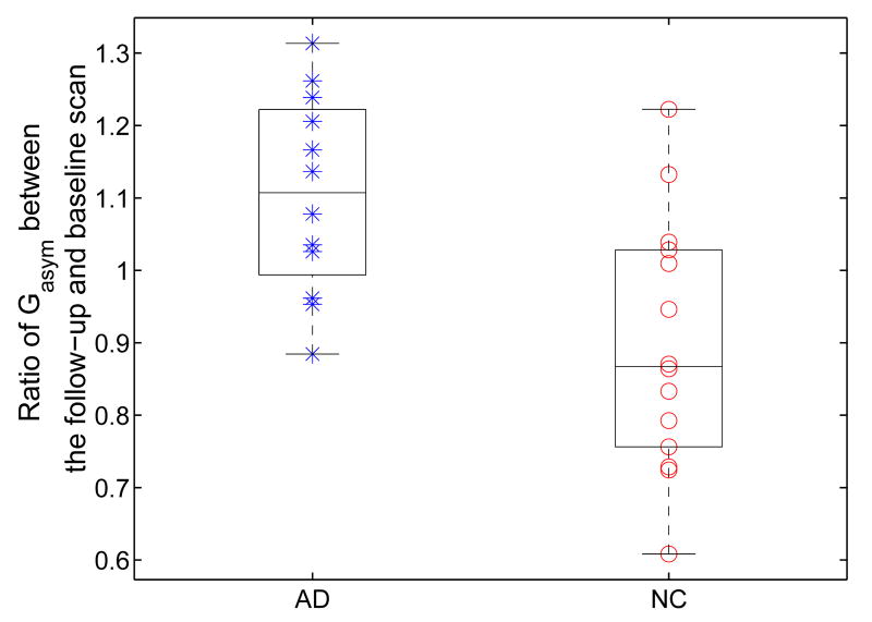
In this experiment, we apply our direct mapping method to study the temporal changes of HC asymmetry. As an example, we first show the mapping results between the left and right HC surface of a subject. The high resolution left and right HC surface are shown in Fig. 14(a) and (b). The landmark curves are plotted on the lower resolution surfaces in Fig. 14(c) and (d) for both shapes. Once again, the mapping result is visualized by projecting the zebra pattern on the left HC in Fig. 15(a) to the right HC as shown in Fig. 15(b). This illustrates the invariance of our method as it successfully computed a direct map that established correspondences between the left and right HC surface even though they had very different poses. With this map from the left to the right HC surface, a rigid transform was computed to align them so the asymmetry measures in Eq. (13) and (14) can be computed. Both surfaces are shown together in Fig. 16(a) and (b) after applying the rigid transform to the right HC surface, and we can see very good alignment has been obtained. To study temporal changes of HC asymmetry, we computed the global asymmetry between the left and right HC surface of each subject at both the baseline and follow-up scan. The results for both the group of AD patients and normal controls are shown as scatter plots with whisker boxes in Fig. 17. A t-test was performed for each group with respect to the hypothesis of no change. The result is significant for the AD group with a P value of 0.0275 and the mean change is 175. For the group of normal controls, the mean change is −236 and the P value is 0.0563 and close to be significant. To account for scale differences between subjects, we calculated for each subject the ratio of its global asymmetry at the follow-up scan to that of the baseline scan. For both the AD and control group, the results are shown as scatter plots together with their whisker plots in Fig. 18. From this plot we can see that AD patients tend to have larger temporal changes of HC asymmetry compared to normal controls. To test the statistical significance of the difference of these two groups, we applied the Wilcoxon rank-sum nonparametric test and obtained a significant P value of 0.0043.
Fig. 14.
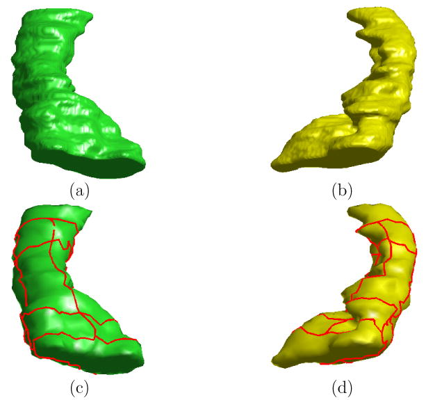
Direct mapping from the left HC surface to the right HC surface of the same subject. (a) The high resolution left HC surface. (b) The high resolution right HC surface. (c) Landmark curves plotted in red on lower resolution left surface from remeshing. (d) Landmark curves plotted in red on lower resolution right surface from remeshing.
Fig. 15.
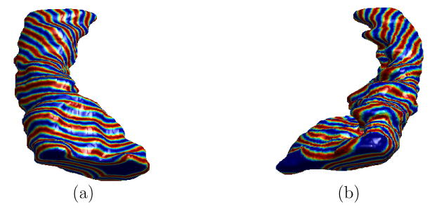
Visualization of the direct map from the left to the right HC surface. (a) The zebra pattern on the high resolution left surface. (b) Projection of the zebra pattern onto the high resolution right surface using the direct map.
Fig. 16.
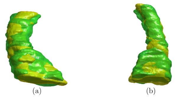
Alignment of the right HC (brown) to left HC (green) visualized from two views. (a) View one from the bottom. (b) View two from the top.
Fig. 17.
Global asymmetry of HC surfaces. (a) AD patients. (b) Normal controls (NC).
Fig. 18.
Temporal changes of global HC Asymmetry.
From the above results, we can see that the asymmetry of the AD group increases over time while the asymmetry of the control group has a trend of decreasing. This opposite trend in temporal changes of HC asymmetry suggests different processes of volume losses could exist between these two groups. For the same data set, different volume loss rates between the AD and controls were reported (Thompson et al., 2004). For the group of AD patients, the right hippocampi have higher volume loss rates than the left hippocampi. On the other hand, the left hippocampi have higher volume loss rates than the right hippocampi in the group of normal controls. Our asymmetry mapping results further validate this opposite trend of volume loss rates between these two groups.
Using our direct mapping method, we can also localize asymmetry changes over time and test their significance. For each subject in our study, we first computed a map from its left HC surface from the baseline scan to its left HC surface from the follow-up scan, so correspondences between points on the two surfaces were established. For every pair of corresponding points of the two surfaces, their ratio of local asymmetry Lasym between the follow-up scan and the baseline scan was then computed to obtain a map of temporal changes of local asymmetry on the left HC surface of the baseline scan. This map of local asymmetry ratio was projected onto the HC atlas in Fig. 13 by computing a direct map from the left HC surface at the baseline scan to the atlas. After the temporal changes of local asymmetry from all the subjects are mapped onto the HC atlas, a Wilcoxon rank-sum nonparametric test was applied at each of the 2000 vertices on the HC atlas to test for significant group differences. As a result of the test, a P value was obtained at each vertex indicating the significance of the group difference. This map of the P value on the HC atlas is shown in Fig. 19, which shows significant differences tend to occur in the head and tail regions. To test the overall statistical significance of this P-value map, we applied a permutation test (Nichols and Holmes, 2002; Thompson et al., 2003, 2004) to take into account the effect of multiple comparisons. Permutation test can measure the distribution of features, which is the area of the HC atlas with P value less than 0.05 in our current test, derived from statistical maps and compute an overall P value that reflects the chance of the current pattern occurring by accident. We applied the permutation test 1 million times and the map in Fig. 19 was confirmed to be significant with an overall P value of 0.012.
Fig. 19.
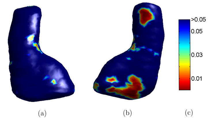
The P-Value map of local asymmetry changes. (a) View one from the bottom. (b) View two from the top. (c) Colorbar.
3.3 SPHARM Analysis of HC Surfaces
We apply the SPHARM analysis techniques based on our direct mapping method to analyze HC surfaces in this experiment. To demonstrate this approach, we computed the map from the HC surface in Fig. 10(a) to the sphere with landmarks shown in Fig. 9. Using this map, the zebra pattern on the HC surface, as shown in Fig. 11(a), was projected onto the sphere and visualized in Fig. 20. We can see this pattern is mapped smoothly onto the sphere. Using this mapping result, we computed the approximation of the HC surface with SPHARM at the order of L = 1, 5, 10, 15, 20, 25 and the results are shown in Fig. 21. With the increase of the approximation order, we can see better reconstructions are obtained. Besides the order L, the accuracy of the SPHARM representation also depends on the quality of the spherical map. For example, the average distance from the point on the reconstructed surface at the order L = 25 in Fig. 21 to their corresponding points on the original surface in Fig. 10(a) is 0.147mm. If we use the initial map from the HC surface to the sphere to compute the SPHARM representation, this average distance is 0.204mm, which shows the distortion resulting from the spherical mapping process is reduced by 28% through the minimization of the harmonic energy in our algorithm. We can also see in Fig. 21 that the improvement to the reconstructed surface becomes very slow after L = 10. This suggests that SPHARM representation provides a way of dimension reduction for shape analysis. One advantage of this dimension reduction is that it could improve numerical efficiency in statistical analysis of group studies. By eliminating high frequency components that may only reflect individual differences, SPHARM analysis could also potentially improve the sensitivity of statistical analyses.
Fig. 20.
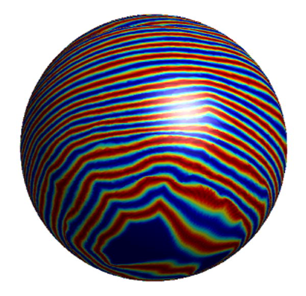
Zebra pattern in Fig. 11(a) projected onto the sphere.
Fig. 21.
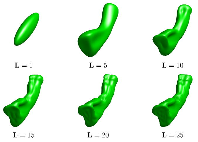
Approximation of the HC surface in Fig. 10(a) with spherical harmonic functions up to the order L = 1, 5, 10, 15, 20, 25.
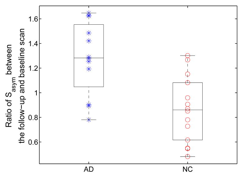
We next apply SPHARM analysis to study the temporal changes of asymmetry. In our experiment, we chose the order L = 10 to compute Sasym in Eq. (17), which was selected such that the asymmetry measure on average accounts for 95% of the overall difference, which can be measured with L = ∞ in Eq. (17), for both the AD and control group. For each subject from both the AD and control group, we also computed the average approximation error of SPHARM approximation at L = 10. A t-test was applied to the approximation errors of the AD and control group and the P value is 0.44, so no group differences were detected with this specific selection of approximation order. The results of temporal changes of HC asymmetry measured by Sasym are shown in Fig. 22. The Wilcoxon rank-sum nonparametric test was again applied to test group differences and the P value is 0.0031. From the results in Fig. 22, we see that opposite trends are also followed for the temporal changes of HC asymmetry from the AD and control group. This confirms the results in the previous experiment shown in Fig. 18, but the differences between the two groups here are more separated. This is probably due to the power of the SPHARM analysis to filter out unimportant details by constraining our analysis to a subspace of low dimensions. One limitation of SPHARM analysis, however, is that it can only provide a global measure of shape properties, while the asymmetry measure in Eq. (13) and (14) use direct maps between HC surfaces and can produce detailed local asymmetry changes as shown in Fig. 19.
Fig. 22.
Temporal changes of HC asymmetry for the group of AD patients and normal controls (NC) from SPHARM analysis.
4 Discussion and Conclusions
We have presented a new method for the mapping of HC surfaces with a set of automatically detected landmark curves. In our method, we treat the boundary of the hippocampus as a genus zero surface, which is the approach taken by most previous works on HC shape analysis. It should be noted that this is not the only way to study the morphology of hippocampi. The gray matter sheet of the hippocampus can also be treated as a surface with boundary in and interesting findings were reported in functional studies (Zeineh et al., 2003).
An important property of our method is the utilization of intrinsic features that are detected automatically. This makes the resulted mapping process invariant to the pose of HC shapes. In our study of HC asymmetry, we have computed maps from the left to the right HC surface without first aligning them, which eliminates the impact of factors such as orientation and location on the final map. After the map is computed, we then align them and compute the asymmetry using the detailed point correspondences. This process of first-map-then-align is different from previous approaches of studying HC asymmetry (Wang et al., 2001; Shenton et al., 2002) where alignment was a preprocessing step before detailed correspondences can be established. Methods based on medial models (Thompson et al., 2004; Narr et al., 2004; Styner et al., 2003; Fletcher et al., 2004; Bouix et al., 2005) also have the property of pose invariance, however they usually assume a simplified topology about the medial model of the HC surface such that correspondences on the medial models can be established, while our method provides a detailed map on the HC surface.
The landmark curves in our algorithm are derived automatically according to the intrinsic geometry of HC surfaces and they are used to guide the mapping between HC surfaces with the goal of improving functional homology. We demonstrated in our experiments that these landmark curves can be robustly extracted on more than one hundred HC surfaces. This shows they are able to capture the geometric regularity among HC surfaces. It is important to evaluate how well these geometric features correlate with boundaries of cellular fields in the hippocampus formation, but they are hard to identify at the current resolution of typical MRI images. With the increasing popularity of 7T MRI imaging technology (Augustinack et al., 2005; Xu et al., 2006), however, it is very promising that we will be able to reliably delineate these structures inside the hippocampus. When such anatomical boundaries are available, we can not only use them to validate our geometric landmark curves, but also use them to guide the mapping between HC surfaces as our direct mapping method is able to incorporate general landmark curves as boundary conditions. By defining a set of corresponding curves on the sphere, we have applied our mapping method to compute spherical maps of HC surfaces. Once the spherical map is available, we follow previous works (Brechbühler et al., 1995; Kelemen et al., 1999; Gerig et al., 2001; Shenton et al., 2002; Shen et al., 2003) to perform SPHARM analysis. It is also possible to combine our direct mapping method with the SPHARM analysis tools from the above works by using the direct mapping results to provide the alignment needed in establishing correspondences between spherical mapping results of different HC surfaces.
We used the approach of solving PDEs on implicit surfaces to compute the map as the minimizer of the harmonic energy under landmark constraints. One advantage of the implicit approach is that we can use numerical schemes on regular grids to compute intrinsic derivatives such as the Laplace-Beltrami operator. The implicit mapping method is also not limited to minimize the harmonic energy and it is possible to include general data terms that are designed to match specific applications.
We have applied our method to the study of temporal changes of HC asymmetry in AD from baseline to follow-up scans to demonstrate its usefulness in neuroscience research. Statistically significant results have been obtained that show the AD group has an opposite trend in temporal changes of HC asymmetry than the group of normal controls. This result has been confirmed by both the direct mapping results and SPHARM analysis. It is also possible to incorporate detailed time differences between scans into the statistical analysis, but this requires making assumptions about the rate of change and can amplify the noise in the manually traced data. For example, using the same data in Fig. 17(a) and (b), the Wilcoxon rank-sum test gives a P value of 0.0094 for annualized HC asymmetry changes if we assume the HC asymmetry changes linearly over time. This P value is slightly bigger than the one we reported in section 3.2, possibly due to the change of noise statistics in computing the annualized rate of changes, but it still suggests the difference in the temporal changes of HC asymmetry between the AD and control group is statistically significant.
Using the direct mapping method, we also obtained a detailed map of P values of local asymmetry changes across time. This map suggests significant changes are localized to the head and tail regions. Because the HC surfaces are reconstructed from manually traced contours, it is important to keep in mind possible errors from this source when interpreting the mapping result. The difficulty in accurately delineating the anterior boundary between the hippocampus and amygdala might affect the mapping result in the head part of the HC surface(Pruessner et al., 2000). If the errors in manual tracing are random, our statistical analysis should still pick up the right trend in the data unless there is a systematic bias in the tracing process, which is unlikely since the reliability of the tracing method was shown to be high and the tracer was blind to diagnostics (Thompson et al., 2004). Due to the limited sample size of our data, it is also interesting to further validate the mapping result when larger data sets are available.
In our future work, we will apply our method to the studies of other diseases such as schizophrenia (Narr et al., 2004) and HC morphology in normal development. Besides SPHARM analysis, we will also investigate the application of other standard shape analysis tools, for example the principal component analysis (Cootes et al., 1995), to our mapping results.
5 Appendix
Here we give the numerical details of evaluating the contribution of each triangle to the integral for the purpose of computing the ISC feature hp(k) at a vertex p on the surface M = (V, T).
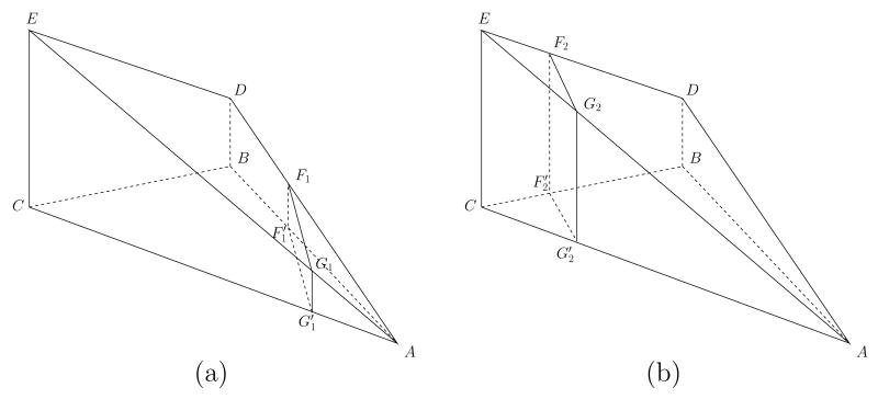
Let Ti = {A, B, C} be a triangle in T with three vertices A, B, C. Their geodesic distances to p are dp(A), dp(B) and dp(C). Without loss of generality, we assume dp(A) ≤ dp(B) ≤ dp(C). The area of Ti is denoted as Si. The contribution of this triangle to the integral is the area of the region inside Ti with their geodesic distance to p in the range [k∊, (k+1)∊) where ∊ is the same bin size used in (6). Assuming the function dp(·) is linear inside the triangle, its graph on the triangle is a 2D plane determined by its value at A, B and C. By shifting this plane downward by dp(A), we obtain a pyramid with five vertices A, B, C, D, E as shown in Fig. 23, where the triangle {A, E, D} is the graph of dp(·) − dp(A) and the length of the edges EC and DB are |EC| = dp(C) − dp(A) and |DB| = dp(B) − dp(A).
Fig. 23.
Two cases in the definition of the cumulative function on a triangle using linear interpolation.
Using the above geometric configuration over the triangle Ti, we define a cumulative function Cum(·). For f ≥ 0, the value Cum(f) denotes the area of the region inside Ti with dp(·) < f. Using this cumulative function, the contribution from the triangle Ti to the k-th component of the shape context hp(k) is then
where SM is the surface area of M. Clearly Cum(f) = 0 for f < dp(A) and Cum(f) = Si for f > dp(C). To compute the value of dp(·) for dp(A) ≤ f ≤ dp(C) the set of points in the triangle {A, E, D} with height f − dp(A) is considered. Because dp(·) is assumed linear on Ti, this set is a line and its projection onto the triangle Ti is the set of points with dp(·) = f. There are two possible configurations for this set on the triangle {A, E, D}. When dp(A) ≤ f < dp(B), as shown in Fig. 23(a), this set is a line F1G1 connecting the edges AD and AE and its projection onto Ti is the line that connects the edges AB and AC. The value of the cumulative function Cum(f) corresponds to the area of the triangle . In the second case when f ≥ dp(B), as shown in Fig. 23(b), this set is a line F2G2 that connects the edges DE and AE and its projection onto Ti is the line connecting the edges BC and AC. In this case, the value of the cumulative function Cum(f) is the area of the polygon . Summarizing these cases, the complete definition of the cumulative function is:
| (18) |
Footnotes
Publisher's Disclaimer: This is a PDF file of an unedited manuscript that has been accepted for publication. As a service to our customers we are providing this early version of the manuscript. The manuscript will undergo copyediting, typesetting, and review of the resulting proof before it is published in its final citable form. Please note that during the production process errors may be discovered which could affect the content, and all legal disclaimers that apply to the journal pertain.
References
- Augustinack J, van der Kouwe A, Blackwell M, Salat D, Wiggins C, Frosch M, Wiggins G, Potthast A, Wald L, Fischl B. Detection of entorhinal layer II using 7 Tesla [correction] magnetic resonance imaging. Ann Neurol. 2005;57(4):489–494. doi: 10.1002/ana.20426. [DOI] [PMC free article] [PubMed] [Google Scholar]
- Belongie S, Malik J, Puzicha J. Shape matching and object recognition using shape contexts. IEEE Trans Pattern Anal Machine Intell. 2002;24(4):509–522. [Google Scholar]
- Ben Hamza A, Krim H. Geodesic matching of triangulated surfaces. IEEE Trans Image Processing. 2006;15(8):2249–2258. doi: 10.1109/tip.2006.875250. [DOI] [PubMed] [Google Scholar]
- Bertalmío M, Cheng L, Osher S, Sapiro G. Variational problems and partial differential equations on implicit surfaces. Journal of Computational Physics. 2001;174(2):759–780. [Google Scholar]
- Blum H, Nagel R. Shape description using weighted symmetric axis features. Pattern Recognition. 1978;10(3):167–180. [Google Scholar]
- Bookstein FL. Shape and the information in medical images: A decade of the morphometric synthesis. Computer Vision and Image Understanding. 1997;66(2):97–118. [Google Scholar]
- Bouix S, Pruessner JC, Collins DL, Siddiqi K. Hippocampal shape analysis using medial surfaces. NeuroImage. 2005;25(4):1077–1089. doi: 10.1016/j.neuroimage.2004.12.051. [DOI] [PubMed] [Google Scholar]
- Brechbühler C, Gerig G, Kübler O. Parameterization of closed surfaces for 3-D shape description. CVGIP: Image Understanding. 1995;61(2):154–170. [Google Scholar]
- Christensen GE, Rabbitt RD, Miller MI. Deformable templates using large deformation kinematics. IEEE Trans Imag Process. 1996;5(10):1435–1447. doi: 10.1109/83.536892. [DOI] [PubMed] [Google Scholar]
- Cootes T, Taylor C, Cooper D, Graham J. Active shape models-their training and application. Computer Vision and Image Understanding. 1995;61(1):38–59. [Google Scholar]
- Csernansky JG, Joshi S, Wang L, Haller JW, Gado M, Miller JP, Grenander U, Miller MI. Hippocampal morphometry in schizophrenia by high dimensional brain mapping. Proc Natl Acad Sci USA. 1998;95(19):11406–11411. doi: 10.1073/pnas.95.19.11406. [DOI] [PMC free article] [PubMed] [Google Scholar]
- Csernansky JG, Wang L, Jones D, Rastogi-Cruz D, Posener JA, Heydebrand G, Miller JP, Miller MI. Hippocampal Deformities in Schizophrenia Characterized by High Dimensional Brain Mapping. Am J Psychiatry. 2002;159(12):2000–2006. doi: 10.1176/appi.ajp.159.12.2000. [DOI] [PubMed] [Google Scholar]
- Csernansky JG, Wang L, Swank J, Miller JP, Gado M, McKeel D, Miller MI, Morris JC. Preclinical detection of alzheimer's disease: hippocampal shape and volume predict dementia onset in the elderly. NeuroImage. 2005;25(3):783–792. doi: 10.1016/j.neuroimage.2004.12.036. [DOI] [PubMed] [Google Scholar]
- Duvernoy H. The human hippocampus : an atlas of applied anatomy. J.F. Bergmann; Munich: 1988. [Google Scholar]
- Elad A, Kimmel R. On bending invariant signatures for surfaces. IEEE Trans Pattern Anal Machine Intell. 2003;25(10):1285–1295. [Google Scholar]
- Fletcher PT, Joshi S, Lu C, Pizer SM. Principal geodesic analysis for the study of nonlinear statistics of shape. IEEE Trans Med Imag. 2004;23(8):995–1005. doi: 10.1109/TMI.2004.831793. [DOI] [PubMed] [Google Scholar]
- Gerig G, Styner M, Jones D, Weinberger D, Lieberman J. Shape analysis of brain ventricles using SPHARM. Proc Workshop on Mathematical Methods in Biomedical Image Analysis. 2001:171–178. [Google Scholar]
- Golland P, Grimson W, Kikinis R. Statistical shape analysis using fixed topology skeletons: Corpus callosum study. Proc IPMI. 1999:382–387. [Google Scholar]
- Grenander U, Miller MI. Computational anatomy: An emerging discipline. Quarterly of Applied Mathematics LVI. 1998;(4):617–694. [Google Scholar]
- Holm DD, Ratnanather JT, Trouvé A, Younes L. Soliton dynamics in computational anatomy. NeuroImage. 2004;23 1:S170–S178. doi: 10.1016/j.neuroimage.2004.07.017. [DOI] [PubMed] [Google Scholar]
- Johnson AE, Hebert M. Using spin images for efficient object recognition in cluttered 3dscenes. IEEE Trans Pattern Anal Machine Intell. 1999;21(5):433–449. [Google Scholar]
- Joshi S, Miller MI. Landmark matching via large deformation diffeomorphisms. IEEE Trans Imag Process. 2000;9(8):1357–1370. doi: 10.1109/83.855431. [DOI] [PubMed] [Google Scholar]
- Joshi SC, Miller MI, Grenander U. On the geometry and shape of brain sub-manifolds. International Journal of Pattern Recognition and Artificial Intelligence. 1997;11(8):1317–1343. [Google Scholar]
- Jost J. Riemannian Geometry and Geometric Analysis. 3. Springer; 2001. [Google Scholar]
- Kelemen A, Szekely G, Gerig G. Elastic model-based segmentation of 3-d neuroradiological data sets. IEEE Trans Med Imag. 1999;8(10):828–839. doi: 10.1109/42.811260. [DOI] [PubMed] [Google Scholar]
- Kimmel R, Sethian JA. Computing geodesic paths on manifolds. Proc Natl Acad Sci USA. 1998;95(15):8431–8435. doi: 10.1073/pnas.95.15.8431. [DOI] [PMC free article] [PubMed] [Google Scholar]
- Lee JM, Kim SH, Jang DP, Ha TH, Kim JJ, Kim IY, Kwon JS, Kim SI. Deformable model with surface registration for hippocampal shape deformity analysis in schizophrenia. NeuroImage. 2004;22(2):831–840. doi: 10.1016/j.neuroimage.2004.02.004. [DOI] [PubMed] [Google Scholar]
- Lewiner T, Lopes H, Vieira AW, Tavares G. Efficient implementation of Marching Cubes cases with topological guarantees. Journal of Graphics Tools. 2003;8(2):1–15. [Google Scholar]
- Lui LM, Wang Y, Chan TF, Thompson PM. Automatic landmark and its application to the optimization of brain conformal mapping. Proc CVPR. 2006;2:1784–1792. [Google Scholar]
- MacDonald D. PhD thesis. McGill Univ; Canada: 1998. A method for identifying geometrically simple surfaces from threee dimensional images. [Google Scholar]
- Mémoli F, Sapiro G, Osher S. Solving variational problems and partial differential equations mapping into general target manifolds. Journal of Computational Physics. 2004a;195(1):263–292. [Google Scholar]
- Mémoli F, Sapiro G, Thompson PM. Implicit brain imaging. Neuroimage. 2004b;23 1:S179–S188. doi: 10.1016/j.neuroimage.2004.07.072. [DOI] [PubMed] [Google Scholar]
- Narr KL, Cannon TD, Woods RP, Thompson PM, Kim S, Asunction D, van Erp TG, Poutanen VP, Huttunen M, Lonnqvist J, Standerksjold-Nordenstam CG, Kaprio J, Mazziotta JC, Toga AW. Genetic contributions to altered callosal morphology in schizophrenia. J Neurosci. 2002a;22(9):3720–3729. doi: 10.1523/JNEUROSCI.22-09-03720.2002. [DOI] [PMC free article] [PubMed] [Google Scholar]
- Narr KL, Thompson PM, Sharma T, Moussai J, Blanton R, Anvar B, Edris A, Krupp R, Rayman J, Khaledy M, Toga AW. Three-dimensional mapping of temporo-limbic regions and the lateral ventricles in schizophrenia: gender effects. Biol Psychiatry. 2001;50(2):84–97. doi: 10.1016/s0006-3223(00)01120-3. [DOI] [PubMed] [Google Scholar]
- Narr KL, Thompson PM, Szeszko P, Robinson D, Jang S, Woods RP, Kim S, Hayashi KM, Asunction D, Toga AW, Bilder RM. Regional specificity of hippocampal volume reductions in first-episode schizophrenia. NeuroImage. 2004;21(4):1563–1575. doi: 10.1016/j.neuroimage.2003.11.011. [DOI] [PubMed] [Google Scholar]
- Narr KL, van Erp TG, Cannon TD, Woods RP, Thompson PM, Jang S, Blanton R, Poutanen VP, Huttunen M, Lonnqvist J, Standerksjold-Nordenstam CG, Kaprio J, Mazziotta JC, Toga AW. A twin study of genetic contributions to hippocampal morphology in schizophrenia. Neurobiol Dis. 2002b;11(1):83–95. doi: 10.1006/nbdi.2002.0548. [DOI] [PubMed] [Google Scholar]
- Nichols TE, Holmes AP. Nonparametric permutation tests for functional neuroimaging: a primer with examples. Hum Brain Mapp. 2002;15(1):1–15. doi: 10.1002/hbm.1058. [DOI] [PMC free article] [PubMed] [Google Scholar]
- Osher S, Sethian J. Fronts propagation with curvature-dependent speed: algorithms based on Hamilton-Jacobi formulations. Journal of computational physics. 1988;79(1):12–49. [Google Scholar]
- Peyré G, Cohen L. Surface segmentation using geodesic centroidal tesselation. Proc. 2nd International Symposium on 3D Data Processing Visualization and Transmission; 2004. pp. 995–1002. [Google Scholar]
- Peyrée G, Cohen L. Geodesic remeshing using front propagation. Int'l Journal of Computer Vision. 2006;69(1):145–156. [Google Scholar]
- Pizer SM, Fritsch DS, Yushkevich PA, Johnson VE, Chaney EL. Segmentation,registration, and measurement of shape variation via image object shape. IEEE Trans Med Imag. 1999;18(10):851–865. doi: 10.1109/42.811263. [DOI] [PubMed] [Google Scholar]
- Pruessner JC, Li LM, Serles W, Pruessner M, Collins DL, Kabani N, Lupien S, Evans AC. Volumetry of hippocampus and amygdala with high-resolution MRI and threedimensional analysis software: minimizing the discrepancies between laboratories. Cereb Cortex. 2000;10:433–442. doi: 10.1093/cercor/10.4.433. [DOI] [PubMed] [Google Scholar]
- Shen L, Ford J, Makedon F, Wang Y, Steinberg T, Ye S, Saykin A. Morphometric analysis of brain structures for improved discrimination. Proc MICCAI. 2003:513–520. [Google Scholar]
- Shenton ME, Gerig G, McCarley RW, Szekely G, Kikinis R. Amygdala-Hippocampus shape differences in schizophrenia: The application of 3D shape models to volumetric MR data. Psychiatry Research Neuroimaging. 2002;115(12):15–35. doi: 10.1016/s0925-4927(02)00025-2. [DOI] [PMC free article] [PubMed] [Google Scholar]
- Shi Y, Karl W. Real-time tracking using level sets. Proc CVPR. 2005;2:34–41. [Google Scholar]
- Shi Y, Thompson PM, Dinov I, Osher S, Toga AW. Direct cortical mapping via solving partial differential equations on implicit surfaces. accepted to Medical Image Analysis. 2007 doi: 10.1016/j.media.2007.02.001. available at http://dx.doi.org/10.1016/j.media.2007.02.001. [DOI] [PMC free article] [PubMed]
- Squire LR, Stark CE, Clark RE. The medial temporal lobe. Annu Rev Neurosci. 2004;27:279–306. doi: 10.1146/annurev.neuro.27.070203.144130. [DOI] [PubMed] [Google Scholar]
- Styner M, Gerig G, Lieberman J, Jones D, Weinberger D. Statistical shape analysis of neuroanatomical structures based on medial models. Medical Image Analysis. 2003;7(3):207–220. doi: 10.1016/s1361-8415(02)00110-x. [DOI] [PubMed] [Google Scholar]
- Thirion JP. New feature points based on geometric invariants for 3d image registration. Int'l Journal of Computer Vision. 1996;18(2):121–137. [Google Scholar]
- Thompson PM, Hayashi KM, de Zubicaray GI, Janke AL, Rose SE, Semple J, Herman DH, Hong MS, Dittmer SS, Doddrell DM, Toga AW. Dynamics of gray matter loss in Alzheimers disease. J Neurosci. 2003;23(3):994–1005. doi: 10.1523/JNEUROSCI.23-03-00994.2003. [DOI] [PMC free article] [PubMed] [Google Scholar]
- Thompson PM, Hayashi KM, de Zubicaray GI, Janke AL, Rose SE, Semple J, Hong MS, Herman DH, Gravano D, Doddrell DM, Toga AW. Mapping hippocampal and ventricular change in Alzheimer disease. NeuroImage. 2004;22(4):1754–1766. doi: 10.1016/j.neuroimage.2004.03.040. [DOI] [PubMed] [Google Scholar]
- Tu Z, Yuille AL. Shape matching and recognition: Using generative models and informative features. Proc ECCV. 2004;3:195–209. [Google Scholar]
- Vaillant M, Glaunes J. Surface matching via currents. Proc IPMI. 2005:381–392. doi: 10.1007/11505730_32. [DOI] [PubMed] [Google Scholar]
- Vaillant M, Miller MI, Younes L, Trouvé A. Statistics on diffeomorphisms via tangent space representations. NeuroImage. 2004;23 1:S161–S169. doi: 10.1016/j.neuroimage.2004.07.023. [DOI] [PubMed] [Google Scholar]
- Walker MW, Shao L, Volz RA. Estimating 3-D location parameters using dual number quaternions. CVGIP: Image Understanding. 1991;54(3):358–36. [Google Scholar]
- Wang L, Joshi SC, Miller MI, Csernansky JG. Statistical analysis of hippocampal asymmetry in schizophrenia. NeuroImage. 2001;14(3):531–545. doi: 10.1006/nimg.2001.0830. [DOI] [PubMed] [Google Scholar]
- Wang L, Miller JP, Gado MH, McKeel DW, Rothermich M, Miller MI, Morris JC, Csernansky JG. Abnormalities of hippocampal surface structure in very mild dementia of the alzheimer type. NeuroImage. 2006;30(1):52–60. doi: 10.1016/j.neuroimage.2005.09.017. [DOI] [PMC free article] [PubMed] [Google Scholar]
- Wang L, Swank JS, Glick IE, Gado MH, Miller MI, Morris JC, Csernansky JG. Changes in hippocampal volume and shape across time distinguish dementia of the Alzheimer type from healthy aging. NeuroImage. 2003;20(2):667–682. doi: 10.1016/S1053-8119(03)00361-6. [DOI] [PubMed] [Google Scholar]
- Wang Y, Chiang MC, Thompson PM. Automated surface matching using mutual information applied to riemann surface structures. Proc MICCAI. 2005a:666–674. doi: 10.1007/11566489_82. [DOI] [PubMed] [Google Scholar]
- Wang Y, Chiang MC, Thompson PM. Mutual information-based 3D surface matching with applications to face recognition and brain mapping. Proc ICCV. 2005b;1:527–534. [Google Scholar]
- Xu D, Kelley D, Hess K, Mukherjee P, Chen A, Nelson S, Vigneron D. High resolution anatomic imaging of the brain with phased array coils at 7T with comparison to 3T. Magn Reson Imag 2006 submitted to. [Google Scholar]
- Zeineh MM, Engel SA, Thompson PM, Bookheimer SY. Dynamics of the hippocampus during encoding and retrieval of face-name pairs. Science. 2003;299(5606):577–580. doi: 10.1126/science.1077775. [DOI] [PubMed] [Google Scholar]


