

Abstract
Calcium sparks in frog intact skeletal muscle fibers were modeled as stereotypical events that arise from a constant efflux of Ca2+ from a point source for a fixed period of time (e.g., 2.5 pA of Ca2+ current for 4.6 ms; 18°C). The model calculates the local changes in the concentrations of free Ca2+ and of Ca2+ bound to the major intrinsic myoplasmic Ca2+ buffers (troponin, ATP, parvalbumin, and the SR Ca2+ pump) and to the Ca2+ indicator (fluo-3). A distinctive feature of the model is the inclusion of a binding reaction between fluo-3 and myoplasmic proteins, a process that strongly affects fluo-3′s Ca2+-reaction kinetics, its apparent diffusion constant, and hence the morphology of sparks. ΔF/F (the change in fluo-3′s fluorescence divided by its resting fluorescence) was estimated from the calculated changes in fluo-3 convolved with the microscope point-spread function. To facilitate comparisons with measured sparks, noise and other sources of variability were included in a random repetitive fashion to generate a large number of simulated sparks that could be analyzed in the same way as the measured sparks. In the initial simulations, the binding of Ca2+ to the two regulatory sites on troponin was assumed to follow identical and independent binding reactions. These simulations failed to accurately predict the falling phase of the measured sparks. A second set of simulations, which incorporated the idea of positive cooperativity in the binding of Ca2+ to troponin, produced reasonable agreement with the measurements. Under the assumption that the single channel Ca2+ current of a ryanodine receptor (RYR) is 0.5–2 pA, the results suggest that 1–5 active RYRs generate an average Ca2+ spark in a frog intact muscle fiber.
Keywords: spark simulations, ryanodine receptors, fluo-3, excitation-contraction coupling, frog muscle
INTRODUCTION
Ca2+ sparks (Cheng et al., 1993; Tsugorka et al., 1995; Klein et al., 1996) arise from brief, localized releases of Ca2+ from the SR into the myoplasm. In skeletal muscle, the release take places at the triadic junctions through one RYR or a small cluster of RYRs. After release, Ca2+ diffuses throughout the myoplasm and binds to myoplasmic Ca2+ buffers, some of which are also able to diffuse.
A quantitative model of the three-dimensional spread of Ca2+ within the myoplasm of frog muscle was first developed for Ca2+ release by an action potential (Cannell and Allen, 1984). An updated version of this model, also developed for action potential stimulation in frog fibers, provided a good description of both the spatially averaged Ca2+ signal that can be measured with low-affinity Ca2+ indicators (Baylor and Hollingworth, 1998) and the spatially resolved Ca2+ signals that can be measured with a confocal microscope and the high-affinity indicator fluo-3 (Hollingworth et al., 2000). The main goal of this article is to adapt this model for simulations of Ca2+ sparks in frog fibers and to find out whether the properties of the simulated sparks agree with those of measured sparks. Because the properties of Ca2+ sparks in frog intact fibers differ substantially from those in frog cut fibers (Hollingworth et al., 2001), the scope of this article concerns sparks in intact fibers only (18°C).
The general approach is similar to that used previously to model calcium sparks in cardiac myocytes (Pratusevich and Balke, 1996; Izu et al., 1998, 2001; Smith et al., 1998) and frog cut fibers (Jiang et al., 1999; Ríos et al., 1999; Shirokova et al., 1999). Our model assumes that (a) a spark is generated by a brief, constant efflux of Ca2+ from a point source into the myoplasm; (b) the resultant increase in myoplasmic-free [Ca2+] causes increased complexation of Ca2+ with the intrinsic Ca2+ buffers of myoplasm (ATP, parvalbumin, troponin), with the SR Ca2+ pump, and with the indicator used for the spark measurement (fluo-3); (c) gradients in the concentrations of free Ca2+ and in the Ca2+-free and Ca2+-bound forms of the mobile buffers (fluo-3, ATP, parvalbumin) drive diffusive movement of these species away from (or toward) the source; and (d) these processes occur isotropically in myoplasm.
The simulated calcium sparks described in this article were determined from simulated line scan images (x-t images) obtained by convolution of the microscope point-spread function (PSF)* with the calculated distributions of fluo-3 and Cafluo-3. Variability in the sparks was introduced by simulation of photon noise, by random selection of the time of onset of Ca2+ release relative to the time of data sampling, and by random selection of the location of the scan line relative to that of the Ca2+ source (see also Izu et al., 1998). For a particular set of simulated noisy sparks, the duration and amplitude of the Ca2+ source flux were selected so that the mean values of amplitude and rise time would approximately match those of the measurements. The spatial and remaining temporal features of these sparks were then compared with the measurements to assess model performance. These features include full width at half maximum (FWHM), decay time constant, full duration at half maximum (FDHM), late baseline offset, and spark mass (a morphological parameter that emphasizes the three-dimensional nature of a spark; Sun et al., 1998; Shirokova et al., 1999; Hollingworth et al., 2001).
In the initial simulations, the two regulatory sites on troponin were assumed to bind Ca2+ identically and independently. These simulations showed a clear discrepancy between theory and experiment: the decay of the simulated sparks had a slow phase, caused by the dissociation of Ca2+ from troponin, that lagged the decay of measured sparks. A modified model, which incorporated positive cooperativity in the binding of Ca2+ to the two regulatory sites on troponin (Fuchs and Bayuk, 1976; Grabarek et al., 1983), provided a satisfactory simulation of the decay phase as well as of most other properties of measured sparks. The underlying Ca2+ release flux used in this model is 2.5 pA (units of current) for 4.6 ms. If the Ca2+ current through a single open RYR under physiological conditions is 0.5 pA (Kettlun et al., 2000) to 2 pA (Tinker et al., 1993), the results suggest that an average Ca2+ spark in a frog intact fiber is generated by the opening of 1–5 RYRs for 4–5 ms.
Some of the results have appeared in abstract form (Baylor et al., 2002; Chandler et al., 2002).
MATERIALS AND METHODS
Overview of the Spark Model
The model is broadly similar to other models of local Ca2+ movements near a release site inside the myoplasm (see introduction for references). Table I gives several general parameters of the model. The myoplasm is assumed to be isotropic and spherically symmetric. It is subdivided into 101 small compartments by 101 concentric spheres centered at the source of Ca2+ entry. Ca2+ is injected into the innermost compartment (radius, 25 nm) at a constant rate (e.g., 3 pA) for an appropriate period of time (e.g., 5 ms). The concentrations of free [Ca2+], the myoplasmic Ca2+ buffers (troponin, ATP, parvalbumin, the SR Ca2+ pump), and the indicator (fluo-3) are then calculated in all compartments by the simultaneous integration of the appropriate set of first-order differential equations (Eq. A1). Table II , column 2, gives the resting concentrations of Ca2+, Mg2+, the myoplasmic Ca2+ buffers, and the indicator. These are assumed to be uniform throughout the simulation volume; concentrations in the outermost compartment, at 4.975–5.025 μm, are held at these values during the spark. Table II, column 3, gives the diffusion constants for Ca2+ and each of the mobile Ca2+ buffers; the same value is used for the metal-free and metal-bound forms of each particular buffer.
TABLE I.
General Parameters of the Model
| 1 | 2 |
|---|---|
| Temperature | 18°C |
| Sarcomere length | 3.0 μm |
| Radius of the spark source | 25 nm |
| Radius of the simulation volume | 5 μm |
| Number of simulation compartments | 101 |
| Relative fluorescence intensities of fluo-3 | |
| Ca2+-free, protein-free fluo-3 | 0.005 |
| Ca2+-free, protein-bound fluo-3 | 0.01 |
| Ca2+-bound, protein-free fluo-3 | 1 |
| Ca2+-bound, protein-bound fluo-3 | 1 |
| Microscope PSF | |
| FWHMx and FWHMy | 0.2 μm |
| FWHMz | 0.5 μm |
Spherical symmetry is assumed, with a homogeneous distribution of constituents in the resting state. The relative values of fluo-3′s fluorescence intensity are based on the in vitro measurements of Harkins et al. (1993) in the absence and presence of aldolase (the most abundant soluble muscle protein by weight). The microscope PSF is assumed to be a product of Gaussians in x, y, and z (Eq. A3). The indicated values of FWHM are similar to those measured with 0.1 μm fluorescent beads: 0.21 μm in x and y and 0.51 μm in z (Hollingworth et al., 2001).
TABLE II.
Concentrations and Diffusion Constants Assumed in the Model
| 1 | 2 | 3 |
|---|---|---|
| Constituent | Resting concentration |
Diffusion constant |
| μM | 10−6 cm2 s−1 | |
| Resting free [Ca2+] | 0.050 | 3.19 |
| Resting free [Mg2+] | 1,000 | — |
| ATP | 8,000 | 1.49 |
| Troponin (Ca2+ regulatory sites) | 360 | 0 |
| Parvalbumin (Ca2+/Mg2+ sites) | 1,500 | 0.159 |
| Protein (sites for fluo-3 binding) | 3,000 | 0 |
| SR Ca2+ pump (Ca2+ binding sites) | 240 | 0 |
| Fluo-3 | 100 | |
| Protein-free fluo-3 | 11.88 | 1.51 |
| Protein-bound fluo-3 | 88.12 | 0 |
Concentrations are referred to the myoplasmic water volume (Baylor et al., 1983) and, except for Ca2+ and Mg2+, are total concentrations. At a sarcomere length of 3.0 μm, the estimated troponin concentration, if referred to the water volume surrounding the thin filament, is 180 μM; with two Ca2+ regulatory sites per troponin molecule, the concentration of sites is 360 μM. The myoplasmic diffusion constants are for 18°C; they were adjusted from 16°C based on a Q10 of 1.35. The diffusion constants for Ca2+, ATP, and parvalbumin are taken from Baylor and Hollingworth (1998), whereas the value for protein-free fluo-3 is based on the formula given in Zhao et al. (1996), with fluo-3's molecular weight = 765. Because free [Mg2+] is assumed to be constant, the value of its diffusion constant is not used. The 11.88 μM protein-free fluo-3 consists of 10.82 μM Ca2+-free fluo-3 and 1.06 μM Ca2+-bound fluo-3; the 88.12 μM protein-bound fluo-3 consists of 85.88 μM Ca2+-free fluo-3 and 2.24 μM Ca2+-bound fluo-3.
Fig. 1 shows the reaction schemes between Ca2+ (and, if appropriate, Mg2+) and each of the buffers, and between fluo-3 and myoplasmic proteins. The reaction between Ca2+ and the SR Ca2+ pump includes a transport step. Table III gives the values of the rate constants. Most of these values (see below for exceptions) are taken from a previously published model of local Ca2+ movements in frog fibers (Baylor and Hollingworth, 1998; Hollingworth et al., 2000), with adjustments for the average temperature (18°C) and sarcomere length (3.0 μm) of the spark experiments.
Figure 1.

Binding reactions for the myoplasmic constituents included in the simulations; the values of the rate constants are specified in Table III. (A) Equivalent reaction of Ca2+ with ATP in the presence of 1 mM free [Mg2+]. (B) Multistate reaction of Ca2+ and protein (Pr) with fluo-3 (Fluo). (C) Competitive reaction of Ca2+ and Mg2+ with parvalbumin (Parv). (D) Four-state reaction for the binding and transport of Ca2+ by the SR Ca2+ pump (E). (E) One-step reaction between Ca2+ and troponin (Trop), used in Model 1. (F) Two-step reaction between Ca2+ and troponin, used in Model 2.
TABLE III.
Rate Constants Assumed in the Model
| 1 | 2 | 3 | 4 |
|---|---|---|---|
| Reaction | Forward rate | Reverse rate |
Ratio |
| s−1 | |||
| A | |||
| Ca2+ + ATP ⇔ CaATP | 0.1566 × 10⁸ M−1 s−1 * | 34,461 | 2,200 μM |
| B | |||
| Ca2+ + Fluo ⇔ CaFluo | 2.676 × 10⁸ M−1 s−1 | 137 | 0.51 μM |
| Pr + Fluo ⇔ PrFluo | 0.1149 × 10⁸ M−1 s−1 | 4,216 | 367 μM |
| Ca2+ + PrFluo ⇔ CaPrFluo | 0.172 × 10⁸ M−1 s−1 | 32.9 | 1.91 μM |
| Pr + CaFluo ⇔ CaPrFluo | 0.1149 × 10⁸ M−1 s−1 | 15,777 | 1,373 μM |
| C | |||
| Ca2+ + Parv ⇔ CaParv | 0.479 × 10⁸ M−1 s−1 | 0.574 | 0.012 μM |
| Mg2+ + Parv ⇔ MgParv | 0.000379 × 10⁸ M−1 s−1 | 3.45 | 91.0 μM |
| D | |||
| Ca2+ + E ⇔ CaE | 108 M−1 s−1 | 103 | 10 μM |
| CaE ⇔ CaE′ | 500 s−1 | 1,200 | 2.4 |
| Ca2+ + CaE′ ⇔ Ca2E′ | 108 M−1 s−1 | 10 | 0.1 μM |
| Ca2E′ ⇔ E + (2 Ca2+) | 20 s−1 | 0 | 0 |
| E | |||
| Ca2+ + Trop ⇔ CaTrop | 1.017 × 10⁸ M−1 s−1 | 132 | 1.3 μM |
| F | |||
| Ca2+ + Trop ⇔ CaTrop | 2.033 × 10⁸ M−1 s−1 | 2,642 | 13 μM |
| Ca2+ + CaTrop ⇔ Ca2Trop | 1.017 × 10⁸ M−1 s−1 | 13.21 | 0.13 μM |
Letters A–F correspond to the reactions in panels A–F of Fig. 1, where forward and reverse rate constants are denoted by k+i and k−i (i = 1, 2, 3, or 4), respectively. Rates for reactions A, B, C, and E were adjusted to 18°C from those given in Baylor and Hollingworth (1998) and Hollingworth et al. (2000) (Q10 = 2), except for the reaction rates of fluo-3 with protein in B (see materials and methods). Rates for reactions D and F are described in materials and methods. (A) The forward rate for ATP, indicated by an asterisk, is an apparent rate constant in the presence of 1 mM free [Mg2+] (pH = 7, viscosity = 2 centipoise, [K+] = 0.15 M; see Baylor and Hollingworth, 1998). (C) At 50 nM [Ca2+] and 1 mM free [Mg2+], the steady-state occupancy of parvalbumin is 25.8% with Ca2+ and 68.0% with Mg2+; 6.2% is metal-free. (D) The four states of the SR Ca2+ pump are denoted E, CaE, CaE′, and Ca2E′; the parentheses in the fourth line indicate that two Ca2+ ions are released into the lumen of the SR. (E and F) Reaction F is mathematically equivalent to reaction E if (a) the total troponin concentration in reaction F is half that in reaction E, and (b) the values of k−1 and k−2 in Table III F are reduced 20-fold and increased 20-fold, respectively.
The gives additional information about the calculations, including the selection of radii for the concentric spheres, the equations for calculating the concentrations of calcium and the different buffer states, the time steps of the calculation, the equations for transformation from cartesian to polar coordinates, and the equations for the calculation of ΔF/F from Δ[FFluo] and [FFluo]R. ([FFluo] is a derived fluo-3 concentration variable that is linearly related to fluorescence, Eq. A2; the subscript R denotes the resting state.)
Reactions between Ca2+ and its Buffers
ATP is able to react with both Ca2+ and Mg2+. Since the reaction with Mg2+ is extremely rapid, Mg2+ and ATP can be considered to be in equilibrium, at least for the purposes of our calculations. Consequently, the reduced equivalent reaction of Ca2+ with ATP shown in Fig. 1 A can be used (Baylor and Hollingworth, 1998). Table III A gives the apparent rate constants.
Fig. 1 B shows the multistate reaction for the binding of Ca2+ and protein (Pr) with fluo-3 (Harkins et al., 1993; Hollingworth et al., 2000). Protein-bound fluo-3 is assumed to be immobile and to react with Ca2+ with rate constants that are substantially smaller than those assumed for protein-free fluo-3 (Table III B). The eight rate constants in Table III B satisfy k+1 k+4 k−2 k−3 = k+3 k+2 k−4 k−1, the requirement for a noncycling reaction.
Fig. 1 C shows the competitive reactions of Ca2+ and Mg2+ with parvalbumin (Johnson et al., 1981). The rate constants (Table III C) are taken from Baylor and Hollingworth (1998).
Fig. 1 D defines a multistate reaction for the binding and transport of Ca2+ by the SR Ca2+ pump. The first three steps of this reaction are taken from the model of Inesi and de Meis (1989); they specify the sequential binding of two Ca2+ ions to the enzyme. The final step, the transport of Ca2+ into the SR, represents a lumped approximation of the remaining steps in the Inesi and de Meis (1989) model. With [Ca2+]R = 50 nM, the steady-state fractional occupancies of the four enzyme states in Fig. 1 D are 0.9926 (E), 0.0050 (CaE), 0.0021 (CaE′) and 0.0003 (Ca2E′). The steady-state turnover rate versus free [Ca2+] is well described by the Hill equation: rate = Rmax × [Ca2+]N/([Ca2+]N + KD N), in which Rmax, the maximal turnover rate, is 19.23 s−1, KD is 3.57 μM, and N is 1.57. With a total enzyme concentration of 120 μM (Baylor et al., 1983), the maximal rate of Ca2+ removal from the myoplasm is 4.6 mM Ca2+ ions s−1 (= 19.23 s−1 × 120 μM × 2).
Fig. 1, E and F, show two reaction schemes for the binding of Ca2+ to the two Ca2+-regulatory sites on troponin. Fig. 1 E shows the reaction that was used for the first spark simulations, termed Model 1. In this reaction, the two sites are identical and independent (Johnson et al., 1981; Zot and Potter, 1987); the rate constants are given in Table III E.
Fig. 1 F shows the Ca2+-troponin reaction that was used for the final spark simulations, Model 2; the rate constants are given in Table III F. The first Ca2+ ion binds with low affinity (dissociation constant, KD, 13 μM) and the second Ca2+ ion binds with high affinity (KD, 0.13 μM). The steady-state fractional occupancy of the troponin sites as a function of free [Ca2+] is well described by the Hill equation: fractional occupancy = [Ca2+]N/([Ca2+]N + KD N), in which KD = 1.30 μM, and N = 1.89. This value of KD is the geometric mean of the two basic KDs in Model 2 and is identical to the single KD of the troponin reaction in Model 1 (Table III E).
Calculation and Analysis of Noisy Sparks
The first step in the simulations was to calculate the time courses of the concentrations of calcium and the different buffer states in the 101 compartments that extend 5 μm from the spark source. [FFluo] was then calculated from Eq. A2 at the different distances from the source. The PSF of the microscope was approximated as a product of three Gaussian functions (Eq. A3) with FWHMx = 0.2 μm, FWHMy = 0.2 μm, and FWHMz = 0.5 μm (Table I); x and y denote directions perpendicular to the light path and z denotes the direction parallel to the light path. The values of [FFluo] were convolved with the microscope PSF to estimate fluorescence intensity (Eq. A4). Finally, many images of noisy sparks were calculated with the help of a random number generator to mimic several components of variability in the experimental records. In the time domain, simulated spark data were extracted every 2.0 ms, with the registration of the data sampling relative to the onset of Ca2+ release (at the spark source) varied randomly between 0.0 and 1.9 ms in multiples of 0.1 ms. In the space domain, simulated data were extracted every 0.20 μm in x, with the registration of the data sampling relative to the position of the spark source varied randomly between 0.00 and 0.15 μm in multiplies of 0.05 μm. The y and z distances between the scan line and the spark source were varied randomly between 0.00 and 1.00 μm in multiples of 0.05 μm. The photon and instrument noise was simulated by the addition of random noise (standard deviation, ΔF/F = 0.26) to the x-t image.
The final x-t image, of dimensions 14 μm × 170 ms, contained a simulated noisy spark that was positioned near the spatial center of the image and started at ∼50 ms. This image was analyzed in exactly the same way as an experimental x-t image (Hollingworth et al., 2001). First, the simulated image was processed by an automatic spark detection algorithm to identify putative sparks. The temporal waveform of a spark was obtained as the average of the three temporal waveforms at x = −0.2, 0, and 0.2 μm from the estimated center of the spark as determined by the detection algorithim. The spatial waveform at time of peak was obtained as the average of the two spatial waveforms that occurred immediately before and after the estimated time to peak of the spark. The time to peak, and the remaining spark morphological parameters, were determined from fits of standard functions to the spark waveforms in time and space (Eqs. 1 and 2 of Hollingworth et al., 2001; see also Lacampagne et al., 1999). The fitted parameters included rise time, peak amplitude, decay time constant (also called tauoff), FDHM (which reflects both rise time and decay time constant), late baseline offset, FWHM, and spark mass (calculated as 1.206 × amplitude × FWHM3; Hollingworth et al., 2001). Only sparks that satisfied the broad selection criteria described in Hollingworth et al. (2001) were used.
The morphological parameters of the simulated noisy sparks were compared with those of voltage-activated sparks from R. pipiens (Hollingworth et al., 2001). These sparks were measured in intact single fibers in 13 mM [K+] Ringer's (estimated membrane potential, −60 to −65 mV). As described in Hollingworth et al. (2001), raw spark amplitudes were scaled 1.3-fold to give values similar to those expected in normal Ringer's; the factor 1.3 is the mean value of resting F in 13 mM [K+] Ringer's divided by that in normal Ringer's.
Detection of Sparks of Different Amplitudes as a Function of Distance from the Source
Unlike the situation with measured sparks, with simulated sparks, the distance D between the spark source and the intersection of the scan line with the y-z plane is known: 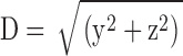 . As the value of D is increased, spark amplitude becomes smaller and the probability of detection decreases (Pratusevich and Balke, 1996; Shirokova and Ríos, 1997; Izu et al., 1998; Cheng et al., 1999; Jiang et al., 1999). The relation between this probability and D was investigated in 200,000 simulations with Model 2 that used a Ca2+ source flux of 2.5 pA for 4.6 ms (see second half of results). Fig. 2 shows results for sparks satisfying three different acceptance criteria for the fitted value of peak amplitude: ΔF/F ≥ 0.3 (asterisks; n = 98,565); ΔF/F ≥ 0.7 (termed “larger” sparks, diamonds; n = 48,827); the largest 10% of the larger sparks (termed “in-focus” sparks, circles; n = 4,883; see last section of results). Fig. 2 A shows the probability that a spark with the appropriate amplitude will be detected at the value of D indicated on the abscissa. For ΔF/F ≥ 0.3, D must be < 0.780 μm for the probability to exceed 0.5. For larger and in-focus sparks, the corresponding distances are 0.553 and 0.172 μm, respectively. As expected, the probability for all three populations goes to 0 at large values of D and is almost 1 at small values of D.
Figure 2.

Probabilities versus D (distance between the spark source and the scan line) for three populations of simulated noisy sparks of different fitted peak amplitudes: ΔF/F ≥ 0.3 (asterisks); ΔF/F ≥ 0.7 (i.e., larger sparks; diamonds); top 10% of larger sparks (i.e., in-focus sparks; circles, for which ΔF/F ≥ 1.55). The results were obtained in Model 2 simulations of 200,000 noisy sparks, as described in materials and methods; the values of Ca2+ flux amplitude and duration were 2.5 pA and 4.6 ms. In A, the ordinate is the probability that a spark at distance D from the scan line satisfies the appropriate amplitude criterion. In B, the ordinate is the probability that the value of D for a spark that satisfies the appropriate amplitude criterion is greater than or equal to the value indicated on the abscissa. In A, the limiting probabilities near 0 μm are slightly <1.0 due to the application of the broad selection criteria given in Hollingworth et al. (2001).
Fig. 2 B shows the probability that a spark with the appropriate amplitude will have a value of D ≥ the value indicated on the abscissa. The plot indicates that half of the sparks with ΔF/F ≥ 0.3 have a value of D ≤ 0.586 μm. The corresponding values of D for the larger and in-focus sparks are 0.411 and 0.152 μm, respectively.
Each amplitude criterion also has an associated “false positive” probability, i.e., a probability that a spark is recognized in an image when, in fact, there is none. When the 200,000 simulations were repeated with a Ca2+ source flux of zero, the corresponding numbers of sparks that satisfied the three amplitude criteria were 18, 1, and 1, respectively, instead of 98,565, 48,827, and 4,883, as indicated above. Thus, false positives do not appear to influence the results of this article, which concern larger and in-focus sparks.
Correction of an Error in an Earlier Version of the Model
Preliminary results with our spark model have been published in abstract form (Baylor et al., 2002; Chandler et al., 2002). When the manuscript for this article was submitted for publication, one of the reviewers expressed concern about a particular simulation result. This concern was addressed with some new calculations, and a programming error was discovered in the value used for the diffusion constant of Ca2+-free protein-free fluo-3. After correction of this error, the concern raised by the reviewer was removed. The conclusions of the abstracts were not changed, although the values of several of the reported numbers were changed slightly in the corrected calculations. For example, the values reported in the abstracts for the Ca2+ flux in our standard spark simulation with Model 2 were 2.7 pA for 4.4 ms compared with the values reported in this article, 2.5 pA for 4.6 ms. The corrected values of all previously published numbers affected by this error appear in column 3 of Tables IV and V of this article.
TABLE IV.
Comparison of Larger Measured and Simulated Sparks (Model 1 and Modifications to Model 1)
| 1 | 2 | 3 | 4 | 5 | 6 | 7 |
|---|---|---|---|---|---|---|
| Parameters and units | Measurements | 50 nM [Ca2+]R
3.3 pA × 5.3 ms |
100 nM [Ca2+]R
6.0 pA × 5.3 ms |
No Ca2+ pump 3.0 pA × 5.3 ms |
No ATP 2.2 pA × 5.3 ms |
Simplified fluo-3 1.7 pA × 5.3 ms |
| Distance (D) (μm) | 0. 362 ± 0.003 | 0.378 ± 0.003 | 0.361 ± 0.003 | 0.329 ± 0.002 | 0.300 ± 0.002 | |
| 0–100% risetime (ms) | 4.176 ± 0.034 (4.55) |
4.202 ± 0.023 (4.66) |
4.215 ± 0.023 (4.66) |
4.165 ± 0.023 (4.66) |
4.148 ± 0.023 (4.67) |
4.294 ± 0.024 (4.58) |
| Peak amplitude (ΔF/F) | 1.082 ± 0.007 (0.97) |
1.087 ± 0.006 (1.09) |
1.084 ± 0.006 (1.09) |
1.076 ± 0.005 (1.07) |
1.088 ± 0.006 (1.12) |
1.098 ± 0.005 (1.17) |
| Decay time constant (ms) | 4.601 ± 0.044 (5.19) |
7.988 ± 0.063 (7.58) |
8.249 ± 0.063 (7.82) |
7.568 ± 0.063 (7.26) |
6.825 ± 0.058 (6.50) |
10.394 ± 0.065 (9.44) |
| FDHM (ms) | 5.923 ± 0.037 (6.56) |
9.199 ± 0.059 (8.57) |
9.540 ± 0.063 (8.75) |
8.734 ± 0.057 (8.32) |
8.119 ± 0.052 (7.78) |
11.631 ± 0.071 (9.85) |
| Late offset (ΔF/F) | 0.0125 ± 0.0010 (0.014) |
0.0598 ± 0.0007 (0.067) |
0.0626 ± 0.0007 (0.069) |
0.0562 ± 0.0007 (0.063) |
0.0606 ± 0.0007 (0.069) |
0.0626 ± 0.0007 (0.070) |
| FWHM (μm) | 1.019 ± 0.007 (0.96) |
0.873 ± 0.004 (0.84) |
0.916 ± 0.004 (0.88) |
0.881 ± 0.004 (0.85) |
0.779 ± 0.004 (0.75) |
0.707 ± 0.003 (0.69) |
| Mass (μm3) | 1.938 ± 0.047 (1.03) |
0.989 ± 0.017 (0.78) |
1.133 ± 0.019 (0.89) |
1.016 ± 0.019 (0.79) |
0.728 ± 0.019 (0.58) |
0.520 ± 0.010 (0.46) |
| Amplitude at 28–48 ms (ΔF/F) | (0.018) | (0.107) | (0.111) | (0.099) | (0.099) | (0.132) |
Nonparenthesized entries (column 2, measured sparks; columns 3–7, simulated sparks) are the mean ± SEM values of the parameters associated with fits to 3,176 individual sparks (amplitude ΔF/F ≥ 0.7), as illustrated in Fig. 3, C–F. In row 1, D denotes the distance between the scan line and the source, which is known in the simulations (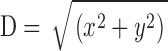 ). All simulated sparks were calculated with the Model 1 troponin reaction (Fig. 1 E) and, except for column 4, with [Ca2+]R = 50 nM. In columns 4–7, the column heading denotes a single modification of the simulation conditions used for column 3 (see text). Parenthesized entries were obtained from fits to the temporal and spatial waveforms of averaged sparks, as illustrated in Fig. 4. All averaged sparks were formed from 1,767 individual sparks aligned at time-of-peak and center location (see Hollingworth et al., 2001); amplitude at 28–48 ms after peak was obtained from Gaussian fits of the type illustrated in Fig. 4, C and F.
TABLE V.
Comparison of Larger Measured and Simulated Sparks (Model 2 and Modifications to Model 2)
| 1 | 2 | 3 | 4 | 5 | 6 | 7 |
|---|---|---|---|---|---|---|
| Parameters and units | Measurements | 50 nM [Ca2+]R
2.5 pA × 4.6 ms |
100 nM [Ca2+]R
4.9 pA × 4.6 ms |
No Ca2+ pump 2.2 pA × 4.6 ms |
No ATP 1.7 pA × 4.6 ms |
Simplified fluo-3 1.3 pA × 4.6 ms |
| Distance (D) (μm) | 0.405 ± 0.003 | 0.420 ± 0.003 | 0.430 ± 0.003 | 0.348 ± 0.002 | 0.350 ± 0.002 | |
| 0–100% risetime (ms) | 4.176 ± 0.034 (4.55) |
4.194 ± 0.023 (4.58) |
4.159 ± 0.023 (4.57) |
4.175 ± 0.023 (4.65) |
4.020 ± 0.021 (4.51) |
4.389 ± 0.026 (4.64) |
| Peak amplitude (ΔF/F) | 1.082 ± 0.007 (0.97) |
1.077 ± 0.005 (1.04) |
1.081 ± 0.006 (1.04) |
1.083 ± 0.006 (1.02) |
1.079 ± 0.005 (1.07) |
1.083 ± 0.005 (1.11) |
| Decay time constant (ms) | 4.601 ± 0.044 (5.19) |
5.747 ± 0.037 (5.72) |
5.981 ± 0.040 (5.91) |
4.706 ± 0.033 (4.70) |
4.933 ± 0.034 (4.88) |
7.270 ± 0.042 (7.04) |
| FDHM (ms) | 5.923 ± 0.037 (6.56) |
6.820 ± 0.030 (6.98) |
7.044 ± 0.032 (7.13) |
6.012 ± 0.025 (6.30) |
6.103 ± 0.026 (6.33) |
8.097 ± 0.033 (7.94) |
| Late offset (ΔF/F) | 0.0125 ± 0.0010 (0.014) |
0.0244 ± 0.0006 (0.025) |
0.0314 ± 0.0006 (0.033) |
0.0202 ± 0.0006 (0.021) |
0.0275 ± 0.0006 (0.029) |
0.0243 ± 0.0007 (0.024) |
| FWHM (μm) | 1.019 ± 0.007 (0.96) |
1.014 ± 0.005 (0.97) |
1.040 ± 0.005 (1.00) |
1.067 ± 0.005 (1.03) |
0.855 ± 0.004 (0.83) |
0.852 ± 0.004 (0.80) |
| Mass (μm3) | 1.938 ± 0.047 (1.03) |
1.528 ± 0.027 (1.14) |
1.646 ± 0.026 (1.24) |
1.784 ± 0.028 (1.37) |
0.947 ± 0.019 (0.73) |
0.922 ± 0.019 (0.69) |
| Amplitude at 28–48 ms (ΔF/F) | (0.018) | (0.030) | (0.040) | (0.023) | (0.031) | (0.041) |
RESULTS
This article compares measured and simulated Ca2+ sparks. The measured sparks were recorded in x-t scans of intact skeletal fibers from R. pipiens (Hollingworth et al., 2001; see materials and methods). For the simulations, a noise-free calculation was performed under a particular set of assumptions and with particular choices for the duration and amplitude of the SR Ca2+ flux. From this, a large number of noisy x-t images that mimicked experimental x-t images were calculated as described in materials and methods. The exact number of noisy x-t images was selected so that the final number of analyzed sparks with peak amplitude ΔF/F ≥ 0.7 (i.e., “larger” sparks) matched that of the measurements (3,176; see below). The duration and amplitude of the SR Ca2+ flux were adjusted in increments of 0.1 ms and 0.1 pA, respectively, so that the mean rise time and amplitude of the larger simulated sparks matched those of the measurements. The remaining morphological parameters were compared with the measured parameters to judge the overall success of the model. Although actual sparks are undoubtedly driven by SR Ca2+ fluxes with different values of duration and amplitude, a single duration and amplitude in the Model 2 simulations (described below) reproduced the main morphological features of the measurements surprisingly well.
Except where noted, simulations were performed with [Ca2+]R = 50 nM. This value is half that assumed in most other spark models, but is close to the mean value of [Ca2+]R estimated for the intact fibers of the spark experiments (Hollingworth et al., 2001).
Spark Simulations with Model 1
The first spark simulations used the one-step Ca2+-troponin binding reaction (Fig. 1 E) with the rate constants given in Table III E (i.e., the Model 1 troponin reaction). Fig. 3, A and B , show noise-free ΔF/F waveforms centered at the spark source, calculated with a Ca2+-release flux of 3.3 pA for 5.3 ms. These parameters were selected so that the larger simulated noisy sparks would have mean values of rise time and amplitude that approximately matched those of the measurements (4.18 ms and 1.08 ΔF/F, respectively; column 2 of Table IV). Fig. 3 A shows the temporal waveform and Fig. 3 B shows the spatial waveform at the time of peak. These traces were obtained from the simulated values of Δ[FFluo]/[FFluo]R after convolution with the microscope PSF (see materials and methods and ). The asterisks in Fig. 3, C and D, show temporal and spatial waveforms, respectively, of a simulated noisy spark with 2-ms and 0.20-μm sampling. In this particular simulation, the scan line was slightly offset from the spark source (0.20 μm in y and 0.15 μm in z), which, on average, reduces spark amplitude. The curves in Fig. 3, C and D, show the best fits of the standard functions to the simulated data, from which the morphological parameters of this spark were obtained (see legend and values printed on the figure panels). Fig. 3, E and F, show similar waveforms and fits from a measured spark (squares).
Figure 3.

Simulated and measured spark waveforms in time (left) and in space (right); in the right panels, the distance axis is parallel to the fiber axis (x direction). (A and B) Noise-free ΔF/F waveforms calculated with Model 1 and an SR Ca2+ flux of 3.3 pA for 5.3 ms. The points are aligned so that the time of spark peak is at 0 ms (A) and the spark center is at 0 μm (B). The distance between the simulated line scan and the source is 0 μm in both y and z. The standard waveform averaging procedures used to reduce noise in the noisy spark waveforms in time and space (see materials and methods) were not applied. (C and D) The asterisks show waveforms from a noisy simulated spark at distances from the source of 0.20 and 0.15 μm in y and z, respectively. Sampling is every 2 ms in C and 0.20 μm in D. Noise was added as described in the text. The curves show fits of the standard functions (Hollingworth et al., 2001). In C, the value of FDHM is 8.32 ms. (E and F) Data (squares) and fits for a measured spark, with the amplitude of ΔF/F referred to Normal Ringer's (see materials and methods). Sampling is every 2.048 ms in E and 0.20 μm in F. In E, the value of FDHM is 6.66 ms.
Simulations and fits like those of Fig. 3, C and D, were repeated 21,183 times, with each simulation determined by a random selection of the sources of noise and variability described in materials and methods. According to the autodetection program (threshold ΔF/F = 0.3 in the 3 × 3 smoothed image), 8,112 of these x-t images had a single spark. Of these, 6,698 passed the broad selection criteria for further spark analysis (Hollingworth et al., 2001) and 3,176 met the amplitude criterion for larger sparks (ΔF/F ≥ 0.7). Table IV, column 3 (entries without parentheses), gives the mean value ± SEM of the distance between the spark source and the scan line (D) followed by the mean values ± SEM of the morphological parameters of these larger simulated sparks. Table IV, column 2, (except for row 1) gives the corresponding values for larger measured sparks.
The corresponding mean values in Table IV, columns 2 and 3, show some similarities and some differences. The mean rise times and amplitudes are nearly identical; this is expected since the duration and amplitude of the Ca2+ release flux were selected to produce good agreement (preceding section). The mean value of FWHM is 14% smaller in the simulations than in the measurements (0.873 and 1.019 μm, respectively), and the mean value of spark mass (= 1.206 × amplitude × FWHM3) is 49% smaller (0.989 and 1.938 μm3, respectively). The latter difference is mainly due to the smaller average value of FWHM in the simulations in combination with the third-power dependence of mass on FWHM (see also section below on “Spark Histograms”).
The other four parameters in Table IV reflect properties of the falling phase of a spark: decay time constant, FDHM, late baseline offset, and ΔF/F at 28–48 ms. The values of these parameters are all substantially larger in the model than in the measurements. The percentage increases are: decay time constant, 74%; FDHM, 55%; late baseline offset, 378%; ΔF/F at 28–48 ms, 494%.
The difference between the simulated and measured sparks is more readily visualized with averaged traces that have reduced noise. The simulated sparks were aligned and averaged in the same way as the measured sparks, based on alignment of the estimated time of peak and the estimated spatial center of the sparks (Fig. 10 of Hollingworth et al., 2001). Fig. 4 shows temporal and spatial waveforms obtained from these averaged sparks (Fig. 4, A–C, simulations, asterisks; Fig. 4, D–F, measurements, squares). The curves in Fig. 4 are fits of the standard functions. The parenthesized values in Table IV, columns 2 and 3, give morphological parameters obtained from these fits (see also values printed on the figure panels).
Figure 4.

Temporal and spatial waveforms from 1,767 averaged simulated (A–C) and measured (D–F) larger sparks. In the simulations, which were made with Model 1, the amplitude and duration of the Ca2+ source flux were 3.3 pA and 5.3 ms. In A and D, the values of FDHM are 8.57 and 6.56 ms, respectively. In B and E, the spatial waveforms were determined at the time of spark peak. In C and F, the spatial waveforms were averaged over the period 28–48 ms after peak; the fitted amplitudes are ΔF/F = 0.107 and 0.018, respectively.
In the time domain (Fig. 4, A and D), the simulated points clearly decay more slowly than the measured data; in addition, the standard function provides a poor fit in A but a good fit in D. In the spatial domain at the time of peak of the spark (Fig. 4, B and E), both the simulated points and the data are reasonably well described by gaussian functions (curves). The fitted value of FWHM is somewhat smaller in the simulations than in the measurements (0.84 and 0.96 μm, respectively). In the spatial domain 28–48 ms after time of peak (Fig. 4, C and F), the amplitude of the simulated points is about sixfold larger than that of the data (0.107 and 0.018, respectively; last row in Table IV). The value of FWHM is somewhat smaller in the simulations than in the measurements (2.11 and 2.94 μm, respectively; see figure panels).
The substantial differences between the values of decay time constant, FDHM, late baseline offset, and ΔF/F at 28–48 ms in Table IV, columns 2 and 3, indicate that one or more of the processes that determine the falling phase of a spark are not well described by Model 1. It was therefore of interest to find out whether a simple modification of the model might provide better agreement with the measurements.
Modifications of Model 1
Model 1 differs in several ways from most previously published spark models. The differences include: (a) the value assumed for [Ca2+]R; (b) the particular reaction chosen for the SR Ca2+ pump; (c) the inclusion of ATP as an endogenous Ca2+ buffer; and (d) the inclusion of a binding reaction between fluo-3 and myoplasmic protein. To evaluate the effect of these differences, the parameters of the model were modified as described in the following paragraphs. In each case, the amplitude of the Ca2+ flux at the source was readjusted so that the mean amplitude of the larger simulated noisy sparks matched that of the measurements. Table IV, columns 4–7 give the morphological parameters obtained in the simulations after these modifications.
The first modification was to increase the value of [Ca2+]R from 50 to 100 nM. The main effect of this change is to increase resting fluorescence (F) by the factor 1.73. The fractional increase in F is smaller than that in [Ca2+]R because the fluorescence of Ca2+-free fluo-3 is not negligible and the binding of Ca2+ to fluo-3 varies slightly nonlinearly with [Ca2+]R. To maintain good agreement between the mean amplitude of the simulated noisy sparks and that of the measurements, it was necessary to increase the amplitude of the SR Ca2+ flux from 3.3 to 6.0 pA. With this change, the mean values of all remaining morphological parameters are very similar to those with [Ca2+]R = 50 nM (Table IV, columns 3 and 4). The largest changes are a 5% increase in FWHM and a 15% increase in spark mass (which has a third-power dependence on FWHM). An increase in FWHM with an increase in [Ca2+]R is expected, because an increase in [Ca2+]R should reduce the resting concentration of Ca2+-free binding sites on troponin and the SR Ca2+ pump (which are immobile Ca2+ buffers) as well as on parvalbumin (which is only slightly mobile). This reduction of Ca2+-free binding sites on molecules with restricted mobility, and the twofold increase in Ca2+ source flux, should allow free Ca2+, CaATP, Cafluo-3, and hence fluo-3 fluorescence to spread more rapidly from the source. Overall, the good agreement between the values in columns 3 and 4 indicates that the differences between Model 1 (column 3) and the measurements (column 2) are not resolved by an increase in [Ca2+]R from 50 to 100 nM.
The next modification was to remove the SR Ca2+ pump (with [Ca2+]R restored to 50 nM). This change required a 9% reduction in Ca2+ release to maintain the mean amplitude of the larger simulated sparks at ΔF/F ≈ 1.08. The values of the other morphological parameters in Table IV, column 5, are similar to those in column 3. The largest changes are 5–6% reductions in decay time constant and late baseline offset. The qualitative explanation is that, with the pump present, some of the Ca2+ that associates with the pump during the rising and early falling phase of the spark is able to dissociate from the pump during the later falling phase (see steps 1–3 in Fig. 1 D). This dissociation of Ca2+ elevates free [Ca2+] and hence fluo-3 fluorescence, thereby prolonging the spark. Overall, the relatively minor changes in morphological parameters associated with removal of the Ca2+ pump make it unlikely that a different reaction scheme for the pump would remove the differences between the values in columns 2 and 3 of Table IV.
The third modification was to set the ATP concentration to zero. Similar to the removal of the SR Ca2+ pump, the removal of ATP is expected to decrease the Ca2+ flux required to maintain a particular spark amplitude and to decrease the decay time constant of the spark. In addition, because ATP constitutes a substantial pool of rapidly reacting, mobile Ca2+ buffer (Baylor and Hollingworth, 1998), removal of ATP is expected to decrease spark FWHM. As shown in Table IV, columns 4 and 6, these expectations are realized. With ATP removed, the Ca2+ flux is reduced by 33% and the mean values of decay time constant and FWHM are reduced by 15% and 11%, respectively; the reduction in spark mass is 26%. These differences in morphological parameters do not reconcile the differences between Model 1 and the measurements (Table IV, columns 2 and 3).
The fourth modification was the elimination of protein from the fluo-3 reactions in Fig. 1 B (“simplified fluo-3” simulation; Table IV, column 7). With only the one-step reaction between Ca2+ and fluo-3 remaining, three other changes were required to make the properties of fluo-3 in the model consistent with those in previous measurements. k+1 and k−1 (Fig. 1 B) were set to 0.402 × 10⁸ M−1 s−1 and 63.2 s−1, respectively, and the diffusion constant of fluo-3 was set to 0.212 × 10⁻⁶ cm2 s−1. These are the apparent values estimated to apply to single effective pools of fluo-3 and Cafluo-3 in intact fibers at 18°C, based on the indicator's apparent diffusion constant measured under resting conditions and its apparent reaction rate constants with Ca2+ measured under action potential conditions (Harkins et al., 1993; Baylor and Hollingworth, 1998). With these modifications, a Ca2+ flux of 1.7 pA (rather than 3.3 pA) is required to maintain the mean spark amplitude near the measured value. The other morphological parameters, however, are changed so as to exaggerate the differences between the simulations and the measurements. Thus, in agreement with the conclusion of Hollingworth et al. (2000), the behavior of fluo-3 in myoplasm is better described by a model that includes reactions between fluo-3 and protein (Fig. 1 B) than by a model that has only single effective pools of fluo-3 and Cafluo-3.
Overall, none of the four modifications in Table IV substantially reduced the discrepancy between the falling phases of the simulated and measured sparks. Furthermore, there is no indication that any combination of the four modifications would reduce the discrepancy. Our conclusion is that some other feature of the model must be modified.
Spark Model 2
At late times, the decay of the sparks simulated with Model 1 is slower than that of the measurements. The likely explanation is that, in the simulations, the Ca2+ that is captured by troponin during the rising and early falling phase of the spark is released during the later falling phase. This released Ca2+ elevates free [Ca2+] and prolongs the decay of [CaFluo] and [CaPrFluo] (Fig. 1 B). Better agreement between the simulations and the measurements might be achieved with a modified troponin reaction in which troponin binds Ca2+ with a greater delay during the rising and early falling phase of the spark and/or releases it more slowly during the later falling phase.
The troponin reaction used in spark Model 2 (Fig. 1 F with the reaction rate constants in Table III F) has these kinetic features. The first Ca2+ ion binds with low affinity and the second ion binds with high affinity. There is a substantial kinetic delay between an increase in [Ca2+] and an increase in the concentration of Ca2+ bound to the high-affinity, slowly dissociating site. This reduces the amount of Ca2+ captured by troponin during the rising and early falling phase of a spark. Then, the slow dissociation of Ca2+ from the high-affinity site decreases the rate at which Ca2+ is released from troponin during the late falling phase of a spark. Hence, [Ca2+], [CaFluo], and [CaPrFluo] are expected to decline more rapidly in Model 2 than in Model 1.
Another difference between the reactions in Fig. 1, E and F, concerns steady-state cooperativity. Ca2+ binding proteins like troponin that have two or more Ca2+ binding sites of the “E-F hand” configuration, often bind Ca2+ with some degree of positive cooperativity (e.g., Ames et al., 1995). Indeed, positive cooperativity has been detected in the binding of Ca2+ to the myofilaments of skeletal muscle (rabbit psoas muscle, pCa's in the range 7 to 5; Fuchs and Bayuk, 1976) and to the regulatory sites of fluorescently labeled troponin reconstituted onto thin filaments (rabbit back and leg muscle; Grabarek et al., 1983). The Ca2+ binding reaction in Fig. 1 F also shows positive cooperativity (steady-state Hill coefficient, 1.89; see materials and methods), whereas the reaction in Fig. 1 E is noncooperative.
The use of the Model 2 troponin reaction is clearly speculative. The reaction between Ca2+ and the regulatory sites on troponin is quite sensitive to experimental conditions (e.g., Grabarek et al., 1983; Rosenfeld and Taylor, 1985; Zot et al., 1986) and the reaction that applies under physiological conditions remains to be determined. Nonetheless, the qualitative expectations described above for the Model 2 troponin reaction encouraged us to explore its properties more fully.
Fig. 5, A and B , illustrate some of the kinetic differences between the Model 1 and Model 2 troponin reactions. In Fig. 5 A, the top trace shows [Ca2+], which is assumed to change in a spatially uniform manner (nonspark situation) from a resting level of 50 nM to 5 μM for a period of 5 ms. The superimposed pair of traces in the middle shows f, the fractional occupancy of the troponin regulatory sites with Ca2+ (continuous trace, Model 1 reaction; dotted trace, Model 2 reaction). The value of f in the Model 2 reaction has a smaller resting value than that in the Model 1 reaction (0.003 vs. 0.037), a slower rising phase in response to the increase in [Ca2+], a smaller peak value (0.515 vs. 0.763), and a markedly slower decline in response to the decrease in [Ca2+]. The superimposed pair of traces at the bottom shows df/dt. After the pulse of [Ca2+], df/dt in the Model 1 reaction shows a substantial negative phase that lasts ∼10 ms, whereas, in the Model 2 reaction, the late phase is greatly reduced. Thus, a Model 2 spark would be expected to have a briefer falling phase than a Model 1 spark.
Figure 5.

Single-compartment calculations that illustrate some of the kinetic differences between the Ca2+ troponin reactions of Models 1 and 2, [Ca2+]R = 50 nM. (A) The top trace top shows a 5-ms pulse in [Ca2+] from 50 nM to 5 μM. The middle traces show the time courses of f, the fraction of the troponin regulatory sites that are occupied with Ca2+ (continuous trace, Model 1 troponin; dotted trace, Model 2 troponin). The bottom traces show the time derivative of the middle traces. (B) Like A for the spatially-averaged free [Ca2+] transient from Baylor and Hollingworth (1998). The peak amplitude and FDHM of the [Ca2+] transient are 18.0 μM and 5.3 ms, respectively.
In Fig. 5 B, the upper trace shows the spatially averaged [Ca2+] waveform estimated for a frog intact fiber stimulated by a single action potential (Baylor and Hollingworth, 1998). The middle traces (f) show that the troponin sites reach nearly full saturation with both the Model 1 and 2 reactions in response to the normal physiological stimulus (peak fractional occupancies, 0.922 and 0.961, respectively). The main difference occurs during the falling phase, where the time course of Ca2+'s dissociation from troponin is noticeably slower in the Model 2 reaction.
Spark Simulations with Model 2
Table V and Figs. 6 and 7 give results for spark simulations performed with Model 2. These are presented in the same formats used for Model 1 (Table IV, Figs. 3, A–D, and 4). As usual, the duration and amplitude of the SR Ca2+ flux were adjusted so that the mean rise time and amplitude of the larger simulated sparks matched those of the measurements. The flux values used for the standard Model 2 simulation (2.5 pA and 4.6 ms; Table V, column 3) are both smaller than the corresponding values used for the standard Model 1 simulations (3.3 pA and 5.3 ms). Compared with Model 1, the Model 2 values of the mean morphological parameters are in substantially better agreement with the measurements (Table V, columns 2 and 3), including the values of FWHM, mass, and the problematic parameters that reflect the falling phase of the spark (decay time constant, FDHM, late baseline offset, ΔF/F at 28–48 ms).
Figure 6.

Simulated spark waveforms calculated with Model 2 and a SR Ca2+ flux of 2.5 pA for 4.6 ms; the format is the same as that in Fig. 3, A–D. In C and D, the distance between the scan line and the spark source is 0.20 μm in y and 0.35 μm in z. In C, the value of FDHM is 6.69 ms.
Figure 7.

Averaged spark waveforms (n = 1,767). (A–C) Calculations with Model 2 and a SR Ca2+ flux of 2.5 pA for 4.6 ms; the format is the same as that in Fig. 4, A–C. In A, the value of FDHM is 6.98 ms. In C, the amplitude of ΔF/F is 0.030. (D–F) These panels are identical to Fig. 4, D–F.
The improvement with Model 2 can also be seen in a comparison of the temporal and spatial waveforms of the averaged sparks (Fig. 7). Although the temporal waveform calculated with Model 1 is poorly fitted by the standard function (curve in Fig. 4 A), the waveform calculated with Model 2 is well fitted (curve in Fig. 7 A), as is the measured waveform (curve in Fig. 7 D). The values of the fitted parameters in Fig. 7, A and D, are also in good agreement. The main discrepancy between the points and the fitted curves in Fig. 7, A and D, occurs 10–40 ms after the peak, where the points lie slightly above the curves. All three spatial waveforms at time of peak are well-fitted by the standard function, although the value of FWHM obtained in the Model 1 fit (0.84 μm; Fig. 4 B) is noticeably smaller than those obtained in the Model 2 fit (0.97 μm; Fig. 7 B) and the measurements (0.96 μm; Fig. 7 E). In all three of these spatial fits, the points near 0 μm and near ±1 μm lie slightly above the curves. Improvement with Model 2 is also apparent in the amplitude of the spatial waveform 28–48 ms after the spark peak. The amplitude of the simulated waveform (0.030, last row in Table V; Fig. 7 C) is substantially closer to that of the measured waveform (0.018; Fig. 7 F) than is the amplitude obtained with Model 1 (0.107; Fig. 4 C).
The four modifications that were applied to Model 1 (Table IV, columns 4–7) gave similar results when applied to Model 2 (Table V, columns 4–7). In Model 2, the reduction in decay time constant associated with removal of the Ca2+ pump is fractionally somewhat greater than that in Model 1 (18% and 5%, respectively). This occurs because, in Model 2, troponin releases Ca2+ at a smaller rate during the falling phase of the spark, so that the dissociation of Ca2+ from the other buffers has a more pronounced effect.
A clear limitation of our simulations is that they use a stereotypical SR Ca2+ release flux (fixed duration and amplitude), whereas the flux that underlies actual sparks undoubtedly involves a range of durations and amplitudes. In addition, some of the reactions between Ca2+ and its buffers, and between fluo-3 and protein, may be more complicated than those shown in Fig. 1. For example, the troponin reaction in Fig. 1 F is the only alternate troponin reaction explored in our simulations and it would be surprising if future studies did not show that the actual reaction is more complicated. On balance, it is remarkable that Model 2, with its many simplifications, is able to reproduce the average properties of measured sparks as well as it does.
Histograms of Spark Morphological Parameters
In Table V, the values of SEM for the simulations are smaller than those for the measurements, indicating less dispersion in the simulated parameters. Fig. 8 gives additional information about this difference in dispersions. In each panel, the normalized histograms show the relative frequency of occurrence of a particular value of a morphological parameter (simulated sparks, asterisks; measured sparks, open squares).
Figure 8.

Relative frequency of particular values of six spark morphological parameters. Asterisks, Model 2 simulations; squares, measured spark data. The mean ± SEM values of the parameters are given in columns 2 and 3 of Table V (n = 3,176).
Fig. 8 A shows the rise time histograms. The value of rise time is thought to closely reflect the duration of the underlying SR calcium release flux responsible for a spark (Cannell et al., 1995). For all simulated sparks, the flux duration was exactly 4.6 ms; thus, the dispersion in the simulated histogram simply reflects the combined effects of the various sources of variability and noise that were used to generate the simulated noisy sparks. The simulated histogram has fewer events at <3 ms and at >6 ms than the measured histogram and a concentration of events between 3 and 6 ms, near the flux duration (4.6 ms). There are two reasons why the actual difference at <3 ms may be more pronounced than that shown in Fig. 8 A. First, the measured histogram may be biased against the inclusion of events that arise from Ca2+ source fluxes of short duration. Such events are likely to be of smaller amplitude (Lacampagne et al., 2000; see also next section) and consequently detected less reliably by our autodetection program. Second, with 2 ms sampling, the rise time of events with a source flux duration <3 ms is expected to be overestimated (Hollingworth et al., 2001). Because of these biases, and the noise level associated with the data points in the measured histogram, no attempt was made to express the measured histogram in terms of a weighted sum of simulated histograms generated with different flux durations. The general similarity of the histograms in Fig. 8 A, however, suggests that the duration of SR Ca2+ release for most larger sparks measured under the conditions of our experiments is narrowly distributed with a mode of 4–5 ms.
Fig. 8 B shows the amplitude histograms. The simulated and measured points are in reasonable agreement, as expected, because of the strong dependence of amplitude on the distance D between the scan line and the source. This dependence should be similar for both simulations and measurements (see also “Properties of In-focus Sparks”).
Fig. 8 C shows the histograms of tauoff (decay time constant). The simulated histogram is right-shifted with respect to the measured histogram, as expected from the mean values in Table V. It also shows slightly less dispersion, which may be due to both intrafiber and interfiber variation in the processes that determine tauoff in the measurements.
Fig. 8 D shows the histograms of late offset. Both histograms have a mode at ΔF/F ≈ 0.02, as expected from the mean values in Table V. The greater dispersion in the measured histogram may reflect variability in fiber properties. It may also reflect small elevations in [Ca2+] produced by subthreshold sparks in the same sarcomere as a detected spark. Such increases in [Ca2+] could bias the estimate of the late offset either up or down, depending on whether the subthreshold activity followed or preceded, respectively, the detected spark.
Fig. 8 E shows the histograms of FWHM. Both histograms have modes near 1.0 μm, but the simulated histogram has less dispersion. The extra events in the measured histogram at FWHM values <0.7 μm are particularly noticeable. They may arise, at least in part, from events with rise times <3 ms (Fig. 8 A); these allow less time for the diffusive spread of Ca2+, fluo-3, and the other mobile Ca2+ buffers from the source at the time FWHM is estimated.
Fig. 8 F shows the histograms of spark mass. The simulated histogram has a well-defined mode near 1 μm3, whereas the measured histogram shows a significant fraction of events with mass <0.5 μm3. These events undoubtedly arise from measured sparks with small values of FWHM (Fig. 8 E).
The general conclusion of this section is that the value of each morphological parameter obtained from a collection of either simulated or measured sparks shows a large degree of dispersion. With simulated sparks, this occurs even though the model parameters and source flux are constant. In this situation, the dispersion must arise from the simulation of random photon and instrumentation noise, from the random selection of the time of onset of Ca2+ release relative to the time of data sampling, and from the random selection of the location of the scan line relative to that of the Ca2+ source. As shown in Fig. 8, the dispersion of parameters from measured sparks is somewhat greater than that from simulated sparks. Although the factors that are responsible for the dispersion in the simulations are expected to make similar contributions to the dispersion in the measurements, an additional component(s), due to variability in other factors, appears to be present in the measurements. Such factors include the following: (a) the duration and amplitude of the source flux of Ca2+, (b) [Ca2+]R, (c) the concentrations of the myoplasmic Ca2+ buffers (troponin, parvalbumin, the Ca2+ pump, ATP, and fluo-3), (d) anatomic structures that may affect spark spread (the triadic junctions, the myofibrils, the SR, mitochondria, etc.); (e) small fluctuations in [Ca2+] caused by subthreshold sparks.
Effect of Variations In Flux Duration and Amplitude on Spark Morphological Parameters
The extra dispersion in the measured rise-time histogram at <3 ms and >6 ms (Fig. 8 A) suggests that actual sparks have variable durations of Ca2+ source flux. To explore the effect of source duration on the fitted morphological parameters, simulations were done with Model 2 with the standard flux amplitude of 2.5 pA (Table V, column 3) and three additional flux durations (2.0, 3.0 and 6.0 ms) (Table VI , columns 2–4). As the flux duration is increased, the amplitude of ΔF/F is increased, and the likelihood of detection of sparks whose source is away from the scan line is increased. Consequently, the mean value of D is increased (Table VI, row 1). Larger flux durations also increase the mean values of all other morphological parameters. For a twofold increase in duration (from 3.0 to 6.0 ms; columns 3 and 4), the percentage increases in mean parameter values are as follows: rise time (72%), peak amplitude (14%), decay time constant (35%), FDHM (56%), late offset (16%), FWHM (29%), and spark mass (106%).
TABLE VI.
Comparison of Simulated Sparks Elicited by Different Ca2+ Fluxes (Model 2)
| 1 | 2 | 3 | 4 | 5 | 6 | 7 |
|---|---|---|---|---|---|---|
| Parameters and units | 2.5 pA × 2.0 ms | 2.5 pA × 3.0 ms | 2.5 pA × 6.0 ms | 2.0 pA × 4.6 ms | 4.0 pA × 4.6 ms | 5.0 pA × 4.6 ms |
| Distance (D) (μm) | 0.256 ± 0.002 | 0.330 ± 0.003 | 0.447 ± 0.003 | 0.358 ± 0.003 | 0.506 ± 0.003 | 0.559 ± 0.004 |
| 0–100% risetime (ms) | 2.702 ± 0.016 (2.67) |
3.111 ± 0.017 (3.06) |
5.357 ± 0.028 (5.59) |
4.104 ± 0.023 (4.56) |
4.359 ± 0.024 (4.56) |
4.483 ± 0.025 (4.59) |
| Peak amplitude (ΔF/F) | 0.896 ± 0.003 (0.84) |
0.987 ± 0.004 (0.96) |
1.123 ± 0.006 (1.11) |
0.992 ± 0.004 (0.95) |
1.291 ± 0.009 (1.27) |
1.399 ± 0.011 (1.38) |
| Decay time constant (ms) | 4.015 ± 0.030 (4.02) |
4.785 ± 0.033 (4.66) |
6.457 ± 0.039 (6.23) |
5.283 ± 0.037 (5.49) |
6.755 ± 0.040 (6.39) |
7.267 ± 0.043 (6.71) |
| FDHM (ms) | 4.467 ± 0.021 (4.38) |
5.308 ± 0.024 (5.09) |
8.259 ± 0.033 (8.10) |
6.393 ± 0.027 (6.78) |
7.729 ± 0.033 (7.44) |
8.270 ± 0.038 (7.44) |
| Late offset (ΔF/F) | 0.0215 ± 0.0006 (0.016) |
0.0223 ± 0.0007 (0.018) |
0.0258 ± 0.0007 (0.024) |
0.0212 ± 0.0006 (0.020) |
0.0310 ± 0.0007 (0.032) |
0.0373 ± 0.0007 (0.036) |
| FWHM (μm) | 0.811 ± 0.006 (0.78) |
0.874 ± 0.005 (0.85) |
1.125 ± 0.005 (1.06) |
0.966 ± 0.005 (0.92) |
1.112 ± 0.005 (1.05) |
1.163 ± 0.005 (1.09) |
| Mass (μm3) | 0.868 ± 0.035 (0.49) |
1.005 ± 0.024 (0.70) |
2.071 ± 0.027 (1.61) |
1.303 ± 0.026 (0.89) |
2.200 ± 0.026 (1.76) |
2.626 ± 0.030 (2.14) |
| Amplitude at 28–48 ms (ΔF/F) | (0.015) | (0.021) | (0.037) | (0.024) | (0.046) | (0.056) |
The close correlation between flux duration and rise time is expected from the simulations of Cannell et al. (1995). Since rise time, but not flux duration, can be directly estimated from fits to measured sparks, plots were made of various morphological parameters versus rise time. Unfortunately, the plots were noisy and, for each parameter, were not very different for the measurements and the standard simulations with Model 2. With a larger population of measured sparks and/or with more rapid data sampling, correlations between rise time and other morphological parameters of the type suggested in Table VI, columns 2–4, might become detectable.
To examine the effect of flux amplitude on spark properties, simulations were performed with Model 2 at the standard flux duration of 4.6 ms and three additional flux amplitudes (2.0, 4.0, and 5.0 pA) (Table VI, columns 5–7). An increase in flux amplitude, similar to an increase in flux duration, increases spark amplitude. This again increases the likelihood of detection of sparks whose source is away from the scan line, so that the mean value of D is increased. The mean values of the other morphological parameters also increase with flux amplitude. For a twofold increase in flux amplitude (2.0 to 4.0 pA), the increases are as follows: rise time (6%), peak amplitude (30%), decay time constant (28%), FDHM (21%), late offset (46%), FWHM (15%), and spark mass (69%). The 30% increase in spark amplitude is substantially smaller than the 100% increase in flux amplitude.
Properties of In-focus Sparks
As noted in materials and methods, the peak amplitude of a spark decreases as D increases. Other morphological parameters may also depend on D. To reduce such variability, sparks that arose near the Ca2+ source were investigated. These were tentatively identified as the top 10% of the larger sparks (referred to as “in-focus” sparks). In the standard simulations with Model 2, the average value of D for in-focus sparks is 0.15 μm, which is similar to the spacing of the pixels in the measurements, 0.20 μm; in contrast, with larger sparks, the average value of D is 0.41 μm (Table V, column 3).
Table VII compares the properties of in-focus simulated and measured sparks. As expected, the mean peak amplitudes of the in-focus sparks (1.878 and 1.703, Table VII, columns 2 and 3) are substantially larger than those of the larger sparks (1.082 and 1.077, Table V, columns 2 and 3). Overall, the mean morphological values of the in-focus simulated sparks are in fair agreement with those of the measurements. The largest discrepancy concerns spark mass, which is 1.272 μm3 in the simulations and 2.658 μm3 in the measurements. This difference arises because in-focus simulated sparks have, on average, both a smaller peak amplitude and a smaller FWHM than in-focus measured sparks. Although the reason for these latter differences is not known, it may be of interest to explore the possibility that they arise from the expected variability of Ca2+ source fluxes in the measured, but not the simulated, sparks.
TABLE VII.
Comparison of In-focus Measured and Simulated Sparks (Model 2)
| 1 | 2 | 3 |
|---|---|---|
| Parameters and units | Measurements | Simulations 2.5 pA × 4.6 ms |
| Distance (D) (μm) | — | 0.147 ± 0.004 |
| 0–100% risetime (ms) | 3.916 ± 0.079 (4.51) |
3.894 ± 0.040 (4.08) |
| Peak amplitude (ΔF/F) | 1.878 ± 0.024 (1.71) |
1.703 ± 0.007 (1.85) |
| Decay time constant (ms) | 4.377 ± 0.108 (5.14) |
4.528 ± 0.053 (4.40) |
| FDHM (ms) | 5.547 ± 0.096 (6.51) |
5.642 ± 0.036 (5.64) |
| Late offset (ΔF/F) | 0.0221 ± 0.0030 (0.028) |
0.0333 ± 0.0020 (0.035) |
| FWHM (μm) | 0.980 ± 0.016 (0.95) |
0.832 ± 0.008 (0.87) |
| Mass (μm3) | 2.658 ± 0.136 (1.78) |
1.272 ± 0.036 (1.49) |
| Amplitude at 28–48 ms (ΔF/F) | (0.032) | (0.035) |
The format is similar to that of Tables IV–VI. The criterion for an in-focus spark is that its peak amplitude fell within the largest 10% of the larger sparks. For column 2, the largest 10% were first identified in each of the 14 experiments, then combined to form the final population; thus, the average value of [Ca2+]R for the combined set of in-focus measured sparks should be similar to that for the population of larger measured sparks. For column 3, the largest 10% corresponds to ΔF/F > 1.55. Nonparenthesized entries reflect fits to 319 individual sparks; parenthesized entries reflect fits to an averaged spark formed from 179 sparks.
Fig. 9 shows temporal and spatial waveforms for averaged in-focus sparks (simulations, asterisks; measurements, open squares). All waveforms are well-fitted by the standard functions (curves). The morphological parameters obtained from the fits (see figure panels and parenthetical entries in Table VII) indicate that the simulations and the measurements are in reasonable agreement.
Figure 9.

Temporal and spatial waveforms obtained from the average of 179 in-focus sparks; the format is the same as that in Figs. 4 and 7. (A–C) Model 2 simulations with a SR Ca2+ flux of 2.5 pA for 4.6 ms; (D–F) measurements. The values of FDHM are 5.64 ms (A) and 6.51 ms (D). In C and F, the fitted amplitudes of ΔF/F are 0.035 and 0.032, respectively.
The general agreement between columns 2 and 3 in Table VII, and between the averaged waveforms in Fig. 9, A–C and D–F, adds support to the conclusion that Model 2 provides a reasonable simulation of the measurements.
DISCUSSION
This article describes a model of Ca2+ sparks in frog intact skeletal muscle fibers and compares the morphological properties of simulated and measured sparks. Many of the basic features of our model are similar to those of previously published models of sparks and other local Ca2+ movements in skeletal and cardiac muscle (see introduction). Consequently, the properties of our calculated sparks share many similarities with those calculated with the other models, such as a value of FWHM of ∼1.0 μm. Because the average value of FWHM measured in frog cut fibers and cardiac myocytes is 1.3–2.5 μm see Discussion and of Hollingworth et al., 2001, Table VII it is clear that the models do not reproduce the FWHM values of those measurements. A different situation arises, however, when our Model 2 simulations are compared with our intact fiber measurements: for the first time, reasonable agreement is found between the morphological properties of simulated and measured sparks, including the value of FWHM (columns two and three of Tables V and VII).
Our simulations incorporate several novel features not included in previous spark models in skeletal muscle. First, our simulations take into account the effects of random variation on the estimation of the morphological parameters of sparks. These include photon and instrumentation noise as well as variability in spark onset and spark location. This approach permits a more realistic comparison of simulated sparks with measured sparks. Second, our model includes binding reactions between fluo-3 and myoplasmic proteins (Fig. 1 B; see also Izu et al., 2001). In a previous study of spatially resolved fluo-3 Ca2+ signals in frog muscle (Hollingworth et al., 2000), model calculations that included these reactions produced better agreement with the fluorescence measurements than calculations that assumed single pools of fluo-3 and Cafluo-3. As expected from that study, the inclusion of the fluo-3-protein reactions in our spark model produced better agreement with the measurements than the simplified two-state fluo-3 reaction (compare columns 2, 3, and 7 of Tables IV and V). Better agreement with measured sparks after inclusion of the reaction between fluo-3 and protein was also reported in a recent model of Ca2+ sparks in cardiac myocytes (Soeller and Cannell, 2002). Third, our model includes a multistate reaction between Ca2+ and troponin (next section).
Ca2+ Troponin Binding
The properties of calcium sparks are determined by the duration and amplitude of the SR Ca2+ release flux, by the binding reactions between Ca2+ and the myoplasmic Ca2+ buffers (as well as Ca2+ transport by the SR Ca2+ pump), and by the diffusion of Ca2+ and the mobile Ca2+ buffers. The results of this article suggest that the decay phase of a spark in a frog intact muscle fiber (average sarcomere length, 3.0 μm) contains useful information about the binding of Ca2+ to troponin. In the initial simulations (Model 1), the reactions between Ca2+ and the two regulatory sites were assumed to be identical and independent (Fig. 1 E). With this assumption, the morphological parameters that reflect the spark falling phase (decay time constant, FDHM, late baseline offset, and ΔF/F at 28–48 ms) were substantially larger in the simulations than in the measurements (Table IV, columns 2 and 3). In the Model 2 simulations, a two-step binding reaction between Ca2+ and troponin was used (Fig. 1 F, with rate constants given in Table III F). With Model 2, the values of decay time constant, FDHM, ΔF/F at 28–48 ms, and late baseline offset came into good agreement with the measurements, as did the value of FWHM (Table V, columns 2 and 3).
Based on the substantial differences between the Model 1 simulations and the measurements, and on the substantial reduction in these differences with Model 2, we speculate that the binding of Ca2+ to troponin in frog intact skeletal muscle is poorly described by the one-step independent reaction (Fig. 1 E). This possibility has not been deduced from previous Ca2+ indicator studies in skeletal muscle. The alternative proposal considered here, that the Ca2+-troponin reaction is a two-step reaction with positive cooperativity, is supported by some work in the literature (Fuchs and Bayuk, 1976; Grabarek et al., 1983) and merits further investigation.
Calcium Source Flux and the Number of Active RYRs Required Per Spark
This article shows that there is good agreement between Model 2 simulated sparks and experimental sparks (Tables V and VII and Figs. 7–9). This suggests that the Ca2+ source flux that was used for the simulations, 2.5 pA for 4.6 ms (18°C), is similar to that responsible for an average voltage-activated spark in a frog intact muscle fiber under our measurement conditions. At physiological ion concentrations, the single-channel RYR Ca2+ current estimated from bilayer experiments varies between 0.5 pA (Kettlun et al., 2000) and 2 pA (Tinker et al., 1993). If the channel open time during a spark is not interrupted by flickering, these single channel currents indicate that 1–5 RYRs would need to open to give 2.5 pA of Ca2+ source flux for a spark in a frog intact skeletal fiber.
Estimates of the number of RYRs per spark have also been made in frog cut fibers, where the properties of sparks differ significantly from those in intact fibers (see Table VII of Hollingworth et al., 2001). The numbers estimated for cut-fiber sparks cover a wide range: ≤4 (Shtifman et al., 2000), ≥6 (Gonzalez et al., 2000, and 8–60 (Ríos et al., 1999). Our estimate for intact fibers is close to that of Shtifman et al. (2000).
APPENDIX
Numerical Simulation of the Concentrations of Calcium and Calcium Buffers Near a Point Source of Calcium Flux from the SR
The theoretical approach for these simulations is similar to that used by Cannell and Allen (1984), Pratusevich and Balke (1996), Baylor and Hollingworth (1998), Izu et al. (1998)(2001), Smith et al. (1998), Jiang et al. (1999), Ríos et al. (1999), and Shirokova et al. (1999). Ca2+ efflux from a small, almost point source is assumed to start at zero time, to be of constant amplitude, and to stop after a few milliseconds. After Ca2+ exits from the source, it diffuses in the myoplasmic solution and reacts with several different calcium buffers according to the reactions illustrated in Fig. 1: ATP (A), the calcium indicator fluo-3 (B), parvalbumin (C), the SR Ca2+ pump (D), and troponin (E or F). Table II gives the resting concentrations of the buffers and their ligands, which are assumed to be constant in space. Table III gives the values of the rate constants of the various reaction steps. The medium surrounding the source is taken to be isotropic and isopotential. Under these conditions, the equations that describe the changes in concentrations of Ca2+ and the buffer states can each be written in the form,
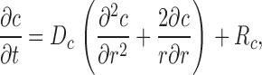 |
(A1) |
in which c is the concentration of Ca2+ or one of the buffer states, t is time, D c is the diffusion constant (equal to 0 if the substance is immobile), r is the distance from the center of the calcium source, and R c is the rate at which c is generated by the reactions illustrated in Fig. 1. In the case of Ca2+ itself, R c also includes any Ca2+ that exits from the source. The first term on the right-hand side of Eq. A1 gives the well known rate of change in concentration for radial diffusion (Crank, 1956).
These equations for the various cs were solved numerically. The volume surrounding the calcium source out to 5.025 μm was separated into 101 regions by the same number of concentric spherical shells. The radius of the first shell, rs(0), is 0.025 μm and the separation between shells is 0.05 μm. Accordingly, r
s(i) = (0.025 + 0.05i) μm, i = 0, 1,…, 100. The volume of the space inside the spherical shell at rs(0), denoted by v(0), is equal to  . The volume of the other spaces, denoted by v(i), is given by
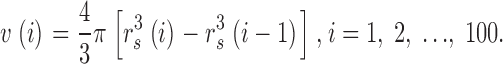 |
Within each volume v(i), the concentration of each substance c is assumed to be constant with a value denoted by c(i) and a position r(i) equal to 0.05i μm, i = 0, 1,…, 100. The source flux of Ca2+ is assumed to enter v(0). The other boundary condition requires that all concentrations inside v(100) are equal to their respective resting values.
A series of differential equations in time were used to describe the changes in the various c(i)s for i = 0, 1,…, 99. These were solved by numerical integration with a modified Runge-Kutta routine (Romanelli, 1960) with an integration step of 1 μs. The total integration time was typically 120 ms after the beginning of Ca2+ release and values of concentrations were usually saved at 0.1-ms intervals.
Fluo-3 Concentrations, Fluo-3 Fluorescence, and the Point Spread Function of the Confocal Microscope
In this article, we assume that fluo-3 can exist in four different states (Fig. 1 B): free (Fluo), bound to Ca2+ (CaFluo), bound to protein (PrFluo), and bound to both Ca2+ and protein (CaPrFluo). The fluorescence of Ca2+-free fluo-3 is small whereas that of fluo-3 bound to Ca2+ is large and assumed to be independent of whether the complex is bound to protein. It is useful to define a new variable FFluo,
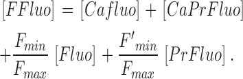 |
(A2) |
F max denotes the relative fluorescence intensity of CaFluo and CaPrFluo; F min and F′min denote the relative fluorescence intensities of Fluo and PrFluo, respectively (Table I). According to this definition, FFluo represents the amount of CaFluo (or CaPrFluo) that would have the same fluorescence as the mixture of all four components. Consequently, fluorescence is linearly related to FFluo.
The spatial resolution of a laser scanning confocal microscope can be described by its point-spread function PSF. In this article, PSF is assumed to be the product of three Gaussian functions, one each for x, y, and z,
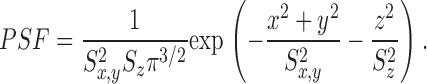 |
(A3) |
The resolution factors S x and S y are expected to be equal since the resolution of the microscope in the plane of the image is independent of x and y; consequently S x = S y = S x,y. The value of S z is, in general, different from that of S x,y. PSF has been normalized so that its volume integral over all space is unity.
For a Gaussian function, the distance parameter S w (with w = x, y, or z) is related to the variance varw by S w 2 = 2varw. The full width at half maximum of the Gaussian function, denoted by FWHM w, is related to S w by FWHM w = 2S w (ln2)1/2. In the calculations described in this article, a value of 0.2 μm was used for FWHM x and FWHM y and 0.5 μm was used for FWHM z (Table I).
The value of fluorescence F(x, y, z, t) produced by FFluo and detected at x, y, z is given by the convolution of [FFluo] with PSF,
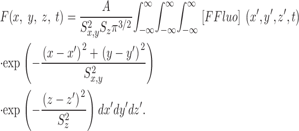 |
(A4) |
A is a constant that depends on several factors. These include the intensity of the laser excitation light that illuminates the spot at x, y, z, the absorbance of the four different states of fluo-3 and their quantum efficiencies for fluorescence, and the efficiency with which the resulting fluorescent light is collected by the microscope and measured by the photodiode(s).
Since the value of [FFluo] depends on r′ (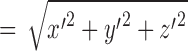 ) and not on the individual values of x′, y′, and z′, it is natural to use spherical polar coordinates with the origin at the center of the calcium source. In this coordinate system, the values of x′, y′, and z′ are given by
 |
 |
 |
and the volume element dx′dy′dz′ is replaced by r′2sinθ9dr′dθ′dφ′. In spherical polar coordinates, Eq. A4 takes the form
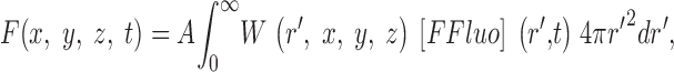 |
in which W(r′, x, y, z) is given by
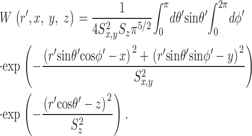 |
Thus,
W
r′,x, y, z=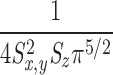
 dθ′sinθ′ ·exp−
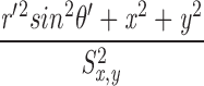 ·exp−
·exp−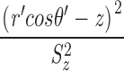 ·
· dφ′exp
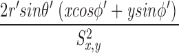 .
.
The integral with respect to φ′ can be evaluated from equation 3.915(4) in Gradshteyn and Ryzhik (1965),
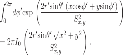 |
(A6) |
in which I 0 represents the modified Bessel function of order 0. Eqs. A5 and A6 can be combined to give
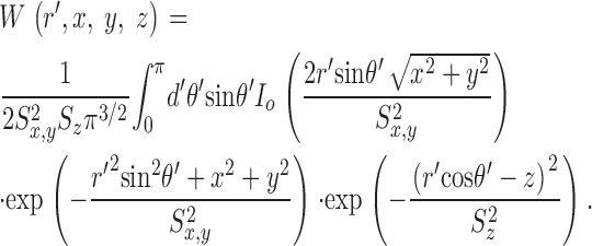 |
(A7) |
Values of W(r′, x, y, z) were obtained from Eq. A7 by numerical integration.
Normalization of ΔF and Δ[FFluo] by their Resting Values
In spark experiments, fluorescence measurements are usually expressed in terms of ΔF/F R, in which the subscript R denotes the resting state and ΔF = F − F R. From Eq. A4,
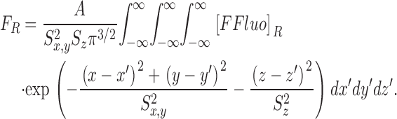 |
Because
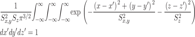 |
for finite x, y, and z,
 |
If Δ[FFluo] is used to represent [FFluo] − [FFluo]R, the following relation, which does not depend on the value of A, is obtained
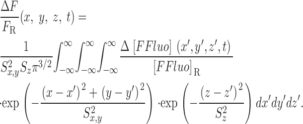 |
Since [FFluo] depends on r′ and not individually on x′, y′, and z′, spherical polar coordinates can be introduced to give
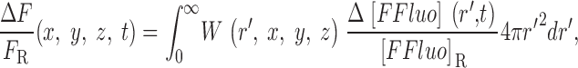 |
(A8) |
in which W(r′, x, y, z) is given by Eq. A7.
In the spark simulations described in the first section of this Appendix and in this article, Eq. A8 is replaced by the summation
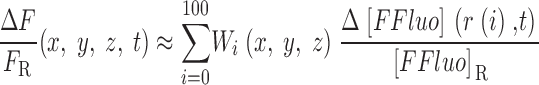 |
in which
 |
with r(−1) set to 0 μm.
Acknowledgments
We thank one of the reviewers of this article for raising a query that led to the discovery of a programming error (see materials and methods).
This work was supported by grants from the U.S. National Institutes of Health to S.M. Baylor (NS 17620) and W.K. Chandler (AM 37643).
Footnotes
Abbreviations used in this paper: FDHM, full duration at half maximum; FWHM, full width at half maximum; PSF, point-spread function.
References
- Ames, J.B., T. Porumb, T. Tanaka, M. Ikura, and L. Stryer. 1995. Amino-terminal myristoylation induces cooperative calcium binding to recoverin. J. Biol. Chem. 270:4526–4533. [DOI] [PubMed] [Google Scholar]
- Baylor, S.M., and S. Hollingworth. 1998. Model of sarcomeric Ca2+ movements, including ATP Ca2+ binding and diffusion, during activation of frog skeletal muscle. J. Gen. Physiol. 112:297–316. [DOI] [PMC free article] [PubMed] [Google Scholar]
- Baylor, S.M., W.K. Chandler, and S. Hollingworth. 2002. Calcium sparks in frog skeletal muscle fibers suggest that the binding of Ca2+ to troponin involves positive cooperativity. Biophys. J. 82:283a. [Google Scholar]
- Baylor, S.M., W.K. Chandler, and M.W. Marshall. 1983. Sarcoplasmic reticulum calcium release in frog skeletal muscle fibres estimated from arsenazo III calcium transients. J. Physiol. 344:625–666. [DOI] [PMC free article] [PubMed] [Google Scholar]
- Cannell, M.B., and D.G. Allen. 1984. Model of calcium movements during activation in the sarcomere of frog skeletal muscle. Biophys. J. 45:913–925. [DOI] [PMC free article] [PubMed] [Google Scholar]
- Cannell, M.B., H. Cheng, and W.J. Lederer. 1995. The control of calcium release in heart muscle. Science. 268:1045–1049. [DOI] [PubMed] [Google Scholar]
- Chandler, W.K., S. Hollingworth, and S.M. Baylor. 2002. Comparison of modeled and measured calcium sparks in intact frog skeletal muscle fibers. Biophys. J. 82:283a. [DOI] [PMC free article] [PubMed] [Google Scholar]
- Cheng, H., W.J. Lederer, and M.B. Cannell. 1993. Calcium sparks: elementary events underlying excitation-contraciton coupling in heart muscle. Science. 262:740–745. [DOI] [PubMed] [Google Scholar]
- Cheng, H., L.-S. Song, N. Shirokova, A. Gonzalez, E.G. Lakatta, E. Ríos, and M.D. Stern. 1999. Amplitude distribution of calcium sparks in confocal images: theory and studies with an automatic detection method. Biophys. J. 76:606–617. [DOI] [PMC free article] [PubMed] [Google Scholar]
- Crank, J. 1956. The Mathematics of Diffusion. Oxford University Press, London. 414 pp.
- Fuchs, F., and M. Bayuk. 1976. Cooperative binding of calcium to glycerinated skeletal muscle fibers. Biochimca Biophysica Acta. 440:448–455. [DOI] [PubMed] [Google Scholar]
- Gonzalez, A., W.G. Kirsch, N. Shirokova, G. Pizarro, G. Brum, I.N. Pessah, H. Cheng, and E. Ríos. 2000. Involvement of multiple intracellular release channels in calcium sparks of skeletal muscle. Proc. Natl. Acad. Sci. USA. 97:4380–4385. [DOI] [PMC free article] [PubMed] [Google Scholar]
- Grabarek, Z., J. Grabarek, P.C. Leavis, and J. Gergely. 1983. Cooperative binding to the Ca2+-specific sites of troponin C in regulated actin and actomyosin. J. Biol. Chem. 258:14098–14102. [PubMed] [Google Scholar]
- Gradshteyn, I.S., and I.M. Ryzhik. 1965. Table of Integrals, Series, and Products. Academic Press, New York and London. 482 pp.
- Harkins, A.B., N. Kurebayashi, and S.M. Baylor. 1993. Resting myoplasmic free calcium in frog skeletal muscle fibers estimated with fluo-3. Biophys. J. 65:865–881. [DOI] [PMC free article] [PubMed] [Google Scholar]
- Hollingworth, S., C. Soeller, S.M. Baylor, and M.B. Cannell. 2000. Sarcomeric Ca2+ gradients during activation of frog skeletal muscle fibres imaged with confocal and 2-photon microscopy. J. Physiol. 526:551–560. [DOI] [PMC free article] [PubMed] [Google Scholar]
- Hollingworth, S., J. Peet, W.K. Chandler, and S.M. Baylor. 2001. Calcium sparks in frog intact skeletal muscle fibers. J. Gen. Physiol. 118:653–678. [DOI] [PMC free article] [PubMed] [Google Scholar]
- Inesi, G., and L. de Meis. 1989. Regulation of steady state filling in sarcoplasmic reticulum. J. Biol. Chem. 264:5929–5936. [PubMed] [Google Scholar]
- Izu, L.T., W.G. Wier, and C.W. Balke. 1998. Theoretical analysis of the Ca2+ spark amplitude distribution. Biophys. J. 75:1144–1162. [DOI] [PMC free article] [PubMed] [Google Scholar]
- Izu, L.T., J.R.H. Mauban, C.W. Balke, and W.G. Wier. 2001. Large currents generate cardiac Ca2+ sparks. Biophys. J. 80:88–102. [DOI] [PMC free article] [PubMed] [Google Scholar]
- Jiang, Y.-H., M.G. Klein, and M.F. Schneider. 1999. Numerical simulation of Ca2+ “sparks” in skeletal muscle. Biophys. J. 77:2333–2357. [DOI] [PMC free article] [PubMed] [Google Scholar]
- Johnson, J.D., D.E. Robinson, S.P. Robertson, A. Schwartz, and J.D. Potter. 1981. Ca2+ exchange with troponin and the regulation of muscle contraction. In Regulation of Muscle Contraction: Excitation-Contraction Coupling, A.D. Grinnell and Mary A.B. Brazier, eds. Academic Press, New York, 241–259.
- Kettlun, C., A. Gonzalez, W. Nonner, E. Ríos, and M. Fill. 2000. Ryanodine receptor (RyR) unitary Ca2+ current is greater in frog skeletal muscle than in mammalian heart. Biophys. J. 78:437a. [Google Scholar]
- Klein, M.G., H. Cheng, L.F. Santana, Y.-H. Jiang, W.J. Lederer, and M.F. Schneider. 1996. Two mechanisms of quantized calcium release in skeletal muscle. Nature. 379:455–458. [DOI] [PubMed] [Google Scholar]
- Lacampagne, A., C.W. Ward, M.G. Klein, and M.F. Schneider. 1999. Time course of individual Ca2+ sparks in frog skeletal muscle recorded at high time resolution. J. Gen. Physiol. 113:187–198. [DOI] [PMC free article] [PubMed] [Google Scholar]
- Lacampagne, A., M.G. Klein, C.W. Ward, and M.F. Schneider. 2000. Two mechanisms for termination of individual Ca2+ sparks in skeletal muscle. Proc. Natl. Acad. Sci. USA. 97:7823–7828. [DOI] [PMC free article] [PubMed] [Google Scholar]
- Romanelli, M.J. 1960. Runge-Kutta methods for the solution of ordinay differential equations. In Mathematical Methods for Digital Computers. vol. 1. A. Ralston and H.S. Wilf, editors. John Wiley & Sons Inc., New York. 110–120.
- Pratusevich, V.R., and W. Balke. 1996. Factors shaping the confocal image of the calcium spark in cardiac muscle cells. Biophys. J. 71:2942–2957. [DOI] [PMC free article] [PubMed] [Google Scholar]
- Ríos, E., M.D. Stern, A. Gonzalez, G. Pizarro, and N. Shirokova. 1999. Calcium release flux underlying Ca2+ sparks of frog skeletal muscle. J. Gen. Physiol. 114:31–48. [DOI] [PMC free article] [PubMed] [Google Scholar]
- Rosenfeld, S.S., and E.W. Taylor. 1985. Kinetic studies of calcium binding to regulatory complexes from skeletal muscle. J. Biol. Chem. 260:252–261. [PubMed] [Google Scholar]
- Shirokova, N., and E. Ríos. 1997. Small event Ca2+ release: a probable precursor of Ca2+ sparks in frog skeletal muscle. J. Gen. Physiol. 502:3–11. [DOI] [PMC free article] [PubMed] [Google Scholar]
- Shirokova, N., A. Gonzales, W.G. Kirsch, E. Ríos, G. Pizarro, M.D. Stern, and H. Cheng. 1999. Calcium sparks: release packets of uncertain origin and fundamental role. J. Gen. Physiol. 113:377–384. [DOI] [PMC free article] [PubMed] [Google Scholar]
- Shtifman, A., C.W. Ward, J. Wang, H.H. Valdivia, and M.F. Schneider. 2000. Effects of Imperatoxin A on local sarcoplasmic reticulum Ca2+ release in frog skeletal muscle. Biophys. J. 79:814–827. [DOI] [PMC free article] [PubMed] [Google Scholar]
- Smith, G.D., J.E. Keizer, M.D. Stern, W.J. Lederer, and H. Cheng. 1998. A simple numerical model of calcium spark formation and detection in cardiac myocytes. Biophys. J. 75:15–32. [DOI] [PMC free article] [PubMed] [Google Scholar]
- Soeller, C., and M.B. Cannell. 2002. Estimation of the sarcoplasmic reticulum Ca2+ release flux underlying Ca2+ sparks. Biophys. J. 82:2396–2414. [DOI] [PMC free article] [PubMed] [Google Scholar]
- Sun, X.-P., N. Callamaras, J.S. Marchant, and I. Parker. 1998. A continuum of InsP3-mediated elementary Ca2+ signalling events in Xenopus oocytes. J. Physiol. 509:67–80. [DOI] [PMC free article] [PubMed] [Google Scholar]
- Tinker, A., A.R.G. Lindsay, and A.J. Williams. 1993. Cation conduction in the calcium release channel of the cardiac sarcoplasmic reticulum under physiological and pathophysiological conditions. Cardiovasc. Res. 27:1820–1825. [DOI] [PubMed] [Google Scholar]
- Tsugorka, A., E. Ríos, and L.A. Blatter. 1995. Imaging elementary events of calcium release in skeletal muscle cells. Science. 269:1723–1726. [DOI] [PubMed] [Google Scholar]
- Zhao, M., S. Hollingworth, and S.M. Baylor. 1996. Properties of tri- and tetra-carboxylate Ca2+ indicators in frog skeletal muscle fibers. Biophys. J. 70:896–916. [DOI] [PMC free article] [PubMed] [Google Scholar]
- Zot, H.G., K. Guth, and J.D. Potter. 1986. Fast skeletal muscle skinned fibers and myofibrils reconstituted with N-terminal analogues of troponin C. J. Biol. Chem. 261:15883–15890. [PubMed] [Google Scholar]
- Zot, H.G., and J.D. Potter. 1987. Calcium binding and fluorescence measurements of dansylaziridine-labelled troponin C in reconstituted thin filaments. J. Muscle Res. Cell Motil. 8:428–436. [DOI] [PubMed] [Google Scholar]