

Abstract
In skeletal muscle, the waveform of Ca2+ release under clamp depolarization exhibits an early peak. Its decay reflects an inactivation, which locally corresponds to the termination of Ca2+ sparks, and is crucial for rapid control. In cardiac muscle, both the frequency of spontaneous sparks (i.e., their activation) and their termination appear to be strongly dependent on the Ca2+ content in the sarcoplasmic reticulum (SR). In skeletal muscle, no such role is established. Seeking a robust measurement of Ca2+ release and a way to reliably modify the SR content, we combined in the same cells the “EGTA/phenol red” method (Pape et al., 1995) to evaluate Ca2+ release, with the “removal” method (Melzer et al., 1987) to evaluate release flux. The cytosol of voltage-clamped frog fibers was equilibrated with EGTA (36 mM), antipyrylazo III, and phenol red, and absorbance changes were monitored simultaneously at three wavelengths, affording largely independent evaluations of Δ[H+] and Δ[Ca2+] from which the amount of released Ca2+ and the release flux were independently derived. Both methods yielded mutually consistent evaluations of flux. While the removal method gave a better kinetic picture of the release waveform, EGTA/phenol red provided continuous reproducible measures of calcium in the SR (CaSR). Steady release permeability (P), reached at the end of a 120-ms pulse, increased as CaSR was progressively reduced by a prior conditioning pulse, reaching 2.34-fold at 25% of resting CaSR (four cells). Peak P, reached early during a pulse, increased proportionally much less with SR depletion, decreasing at very low CaSR. The increase in steady P upon depletion was associated with a slowing of the rate of decay of P after the peak (i.e., a slower inactivation of Ca2+ release). These results are consistent with a major inhibitory effect of cytosolic (rather than intra-SR) Ca2+ on the activity of Ca2+ release channels.
Keywords: sarcoplasmic reticulum, excitation–contraction coupling, Ca channels, channel gating, channel modulation
INTRODUCTION
In striated muscle, contraction is switched on by Ca2+ release from the sarcoplasmic reticulum (SR). In skeletal muscle, Ca2+ release channels are controlled primarily by transverse (T) tubule membrane voltage. In principle, it should also be controlled by Ca2+ ions bound to excitatory and inhibitory cytosol-facing sites, the characterization of which has been done largely in membrane fractions and bilayer-reconstituted ryanodine receptor channels (e.g., Laver et al., 1997). Multiple experimental observations, on skeletal (Ikemoto et al.,1989; Donoso et al.,1995) and cardiac muscle (Gyorke et al., 2002; Terentyev et al., 2002, 2003), complicate this picture. Apparently the SR Ca2+ acting directly on SR-lumenal sites, or perhaps on cytosolic sites upon channel opening, may also modulate and control the state of the channels, and affect the release current. Most interestingly, in heart muscle there is now evidence for a role of the reduction in free lumenal calcium concentration, [Ca2+]SR, consequent to Ca2+ release, in the termination of Ca2+ sparks (Terentyev et al., 2002, 2003). While in skeletal muscle there is no comparable evidence, the issue of spark termination is equally important there, as it underlies the sharp decay of release flux that terminates the early peak observed under voltage clamp, and is understood as crucial in the self-limitation of Ca2+ release necessary to keep the process under voltage control (Stern et al., 1997).
The waveform of Ca2+ release flux elicited by a voltage clamp depolarization pulse exhibits two well-defined kinetic phases. Essentially at all suprathreshold voltages, an early peak of flux is followed by a decay (sometimes oscillatory, see Rengifo et al., 2002) to a quasi-steady level that persists while the pulse is on. 20 yr after the first description of these phases (Baylor et al., 1983; Melzer et al., 1984), there is still no consensus view of their mechanisms. A common belief is that the kinetics are determined by Ca2+ ions, through their dual effects of activation and inhibition/inactivation of ryanodine receptors. But there is no dominant narrative of how interactions of Ca2+ and channels result in two phases under voltage clamp.
The discord starts with the results of experiments repeatedly attempted on the effects of extrinsic Ca2+ buffers, added at concentrations sufficiently high to inhibit local effects of Ca2+. While buffers suppress the kinetic features, leaving a “flat” waveform, some see the effect as a selective loss of the peak phase (Jacquemond et al., 1991; Csernoch et al., 1993), consistent with activation of this phase by Ca2+ (Ca2+-induced Ca2+ release or CICR) as proposed earlier by us (Ríos and Pizarro, 1988). By contrast, other researchers interpret the change to a flat waveform as consequence of suppression by the buffers of the decay that terminates the peak (Baylor and Hollingworth, 1988; Hollingworth et al., 1992). This view supports a Ca2+-dependent inactivation mechanism for the decay (first proposed by Baylor et al., 1983, and further studied by Schneider and Simon, 1988, Simon et al., 1991, and others).
At the root of this discrepancy is the divergent quantification of the waveform of Ca2+ release flux as affected by buffers. While all groups obtain a similar time course, those who support the CICR view report an inhibition of the flux by the buffers (Jacquemond et al., 1991; Csernoch et al., 1993). In contrast, the interpretation based on Ca2+-dependent inactivation requires a promotion of release, especially of its late steady phase, which is what the supporters of this view find in the buffer-modified waveforms (e.g., Hollingworth et al., 1992). Ultimately, the contention on mechanisms simply reflects lack of a uniform scaling of otherwise similar waveforms. In our view there is no common scaling because the methods used to determine flux are different. A main goal of the present work is to resolve these differences by applying both methods simultaneously.
The dissension spills over to the interpretation of the steady level of flux. While the early peak is essential physiologically, as it roughly coincides with the time span of an action potential, the properties of the steady component have been studied as indicators of the underlying mechanisms of control. If the level of flux in this phase may seem constant in the short term (say 100 ms), it is clearly decaying in longer time scales, a decay that has been demonstrated to reflect SR depletion (Schneider et al., 1987b).
Two views have emerged of the behavior of channels during this phase: Schneider et al. (1987b) introduced the assumption that the permeability was constant, hence the decay was a simple consequence of depletion. Under this assumption the flux becomes a proportional indicator of [Ca2+]SR. It is therefore simple to deduce a permeability from the flux measurement, which these workers derive by the “removal” method (i.e., fitting parameters of a common pool model of Ca2+ fluxes in the cytosol; Melzer et al., 1984, 1987). On the other hand Pape et al. (1995) introduced the “EGTA/phenol red” method to quantify Ca2+ release, and interpreted their results to demonstrate an inverse relationship between permeability and SR Ca2+ content.
At the base of the discrepancies are differences in the techniques. The removal method starts from a measure of the Ca2+ concentration transient. In the presence of a slowly equilibrating buffer like EGTA (Smith et al., 1984) at high intracellular concentration, the Ca2+ transient is kinetically very close to release flux (Eq. 17 of Ríos and Pizarro, 1991). More specifically, it equals the sum of a dominant term proportional to release flux, and another roughly proportional to its time integral (Eq. A8 of Pape et al., 1995; Eq. A8 of Song et al., 1998). In contrast, the EGTA/phenol red method derives calcium release from a measure of the H+ transient resulting from stoichiometric displacement by released Ca2+ as it binds to EGTA. The starting signal is in this case an indirect measure of cumulated Ca2+ release, rather than its time derivative. Perhaps as a consequence, the studies with the removal method emphasize kinetic features, especially the distinctive peak of Ca2+ release (Schneider et al., 1987b; Schneider and Simon, 1988; González and Ríos, 1993; Shirokova et al., 1996), while in general the applications of EGTA/phenol red (Pape et al., 1995, 1998, 2002; Pape and Carrier, 1998, 2002; Fénélon and Pape, 2002) have not placed the same level of attention on the separate study of kinetic phases.
To explore how the calcium content of the SR controls the amplitude and time course of Ca2+ release and to understand the differences between the two methods, we combined both approaches and applied them simultaneously, with a pulse protocol that induced variable SR depletion. The determination of Ca2+ release and initial calcium content in the SR (CaSR [0]) allowed us to derive SR content, CaSR(t), at all times, and evaluate the effect of its changes on release flux and release permeability. By applying the two methods in parallel, the kinetic phases of release are resolved reliably and quantitatively. The results reveal different effects of depletion on the kinetic stages of release flux.
MATERIALS AND METHODS
The experiments were performed on single cut muscle fibers voltage clamped in a two-Vaseline gap. This technique has been extensively described (e.g., González and Ríos, 1993). Frogs Rana pipiens were killed by decapitation under deep anesthesia. Both m. semitendinosus were separated and placed in dissection chambers. A 2-cm-long piece of fiber dissected from the muscles was mounted in a three-compartment Lucite chamber where the double Vaseline gap was made. The segments of the fiber in both end compartments were permeabilized by a brief treatment with saponin in order to allow the exchange of the intracellular solution and lower the resistance of the connection to the intracellular space. The preparation was cooled to temperatures between 16 and 18°C by means of a Peltier device.
The fibers were voltage clamped and held at −90 mV. The voltage clamp amplifier was built according to a design of Francini and Stefani (1989). Data acquisition was performed with a 16-bit nominal resolution, 100-kHz board (HSDAS-16; Analogic Corporation). Sampling rate was 20 kHz per channel. Data were filtered before acquisition by an 8-pole Bessel filter at half the frequency of final storage.
Command pulses were generated with the D/A channels of the HSDAS board. As in previous work, solutions were designed to maximize membrane resistance. Membrane currents, membrane voltage, and the change in transmitted light were measured simultaneously during fiber activation by clamp pulses.
Asymmetric currents were obtained as the difference between the membrane current during test pulses and the voltage-scaled current measured during control pulses to −100 mV from a subtracting holding potential of −120 mV. From the asymmetric currents, the intramembranous charge movement transients were obtained by subtraction of sloping baselines separately fitted to late portions of the ON and OFF records.
Solutions
The external solution consisted of 130 mM tetraethylammonium methylsulfonate (TEA-CH3SO3), 10 mM Ca (CH3SO3)2, and 10 mM Tris maleate. pH was titrated to 7 with TEA OH and osmolality to 270 milliosmol/kg. The internal solution, with nominal [Ca2+] of 120 nM and [Mg2+] of 470 μM, had (in mM) 40 Cs-glutamate, 2.8 HEPES, 36 EGTA, 5 Mg ATP, 0.5 MgCl2, 7.0 CaCl2, 5 glucose, 5 phosphocreatine, 0.8 antipyrylazo III (APIII; Sigma-Aldrich), 1.25 phenol red (Sigma-Aldrich). It was titrated with CsOH to pH 7, and set at 260 milliosmol/kg with Cs glutamate. The nominal experiments were conducted at 17 ± 1°C. Relaxing and Ringer's solution formulations were as described by González and Ríos (1993).
Responses of Antipyrylazo III and Phenol Red in Cuvette
Fig. 1 plots absorption spectra of both dyes dissolved in the internal perfusate at various pH values and constant, nominally 0 mM [Ca2+]. Note that ApIII absorption is essentially independent of pH. Note as well the low absorption of the Ca2+-free dye at 720 nm. In contrast, the Ca2+-bound form (Ca ApIII2; Ríos and Schneider 1981) has an absorbance at 720 nm of approximately one third of the maximum absorbance of the free dye, which occurs near 550 nm. This makes 720 an ideal wavelength for Ca2+ detection. Other critical wavelengths are 480 and 620 nm, used for monitoring dye concentrations during the experiments; 560 nm, optimal for the H+ signal of phenol red; 575 nm, which was used instead to minimize interference with ApIII signals because it is closer to the ApIII isosbestic point of 580 nm; and 850 nm, where changes in absorption intrinsic to the muscle fiber are measured without interference from either dye.
Figure 1.

Absorption spectra of phenol red and ApIII at various pH. The figure graphs absorption spectra of intracellular solutions containing 2 mM phenol red (red trace) or 0.88 mM ApIII measured in a 0.1-cm cuvette. Note lack of sensitivity of ApIII absorption to pH.
Extinction coefficients, calculated from calibration curves were (in mM−1 mm−1): ɛ(ApIII, 575) = 2.0; ɛ(ApIII, 480) = 1.27; ɛ(ApIII, 620) = 1.65; ɛ(phenol red, 575) = 2.15; ɛ(H phenol red, 575) = 0.15; ɛ(phenol red, 480) = 1.1; ɛ(phenol red, 620) = 0.07. Extinction coefficients needed for derivation of [Ca2+] from ApIII signals were as used in previous work: ɛ(ApIII, 550) = 2.13 and Δɛ(Ca ApIII2, 720) = 0.56 (suitable for a 50-nm bandwidth filter centered at 720 nm).
A Multibeam Optical Setup
Optical signals were either changes in transmitted light or, in preliminary trials of various dye combinations, fluorescent emission. They were recorded in a multiple beam photometric system assembled around an upright microscope as illustrated in Fig. 2. For simultaneous recording of dynamic signals of ApIII (Ca2+) and phenol red (H+), light coming from halogen source H1 was trimmed by a 550-nm long-pass filter at the filter wheel. The transmitted light was collected by a water immersion objective (N.A. 0.75, 40×; Zeiss Oberkochen) and split by dichroic mirror DM2 at 620 nm. Light of short λ, largely carrying the signal from phenol red, was reflected to photodiode PD2 through a 40-nm width filter centered at 575 nm. The transmitted beam was further split at 800 nm by DM3 into a reflected beam that carried the Ca2+ signal to PD3 and a transmitted beam, which was recorded at PD1, carrying exclusively intrinsic signals. The light reflected onto PD3 was further filtered by a 50-nm width filter centered at 720 nm, while the transmitted light was passed through a 100-nm width filter centered at 850 nm. Source H2 and DM1 were used for superimposing epifluorescence measurements with other dyes, and were withdrawn in other cases. Filters and dichroic mirrors were custom made by Omega Optical, Inc. and photodiodes (HUV-200) purchased from EG&G.
Figure 2.
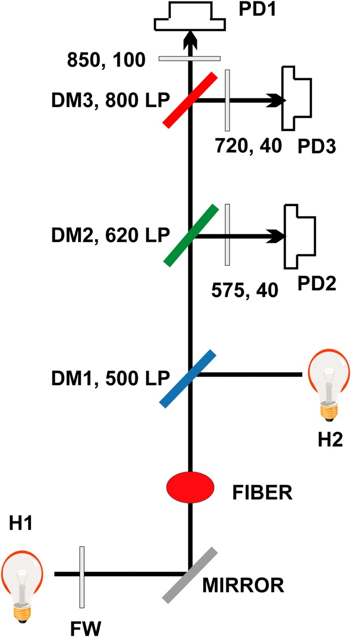
Photometric system. H1, halogen source for transmitted light. FW, filter wheel, with 550 nm long-pass filter for dynamic measurements and band-pass filters at 480 nm (20 nm bandwidth), 575 nm (40), and 620 nm (40) for static evaluation of dye concentrations. Fiber is mounted at stage of upright microscope. Transmitted light is collected by a 40× objective. Halogen or arc lamp source H2, and dichroic mirror DM1 are used for alternative epifluorescence, and withdrawn in most cases. DM2 reflects light of λ < 620 nm, further filtered at 575 nm (40), to photodiode 2. This light largely carries phenol red (H+) signals. DM3 reflects light of λ < 800 nm, further filtered at 720 nm (40), into photodiode 3. This light carries ApIII (Ca2+) signals. The transmitted light, further filtered at 850 nm (100) goes to photodiode 1. It carries intrinsic signals. For static measurements of dye concentration, no filters or mirrors are interposed in the path of transmitted light, which is measured directly by PD1.
Other combinations of dyes were tested for the separation of H+ and Ca2+ signals. BCECF and ApIII were tested combining epi-fluorescence and absorption. To excite BCECF, a 100-W halogen lamp was at H2, its light passed through an excitation filter at 505 nm and was reflected by DM1 at 520 nm. DM2 (560 LP) directed the fluorescent light to PD3 through a barrier filter at 535 nm, other components were unchanged. Carboxy SNARF-1 was paired with Fluo-4 in a fluorescence-only technique (DM1 at 510 nm, DM2 at 550 nm, DM3 at 650 nm, PD2 filter at 530 nm, PD3 at 580 nm). Other combinations were carboxy-fluorescein and Fura red, as well as carboxy-fluorescein and ApIII.
All these combinations produced useful signals. The choice of the ApIII/phenol red pair was dictated more than anything else by the magnitude of their signals, their degree of separation (i.e., minimal mutual interference, illustrated later), and the precision with which the dye concentrations could be determined. The ultimate reasons for these features include that both dyes are “ratiometric” (i.e., have isosbestic wavelengths), the fortunate separation of their spectra, and their limited interference with cellular function, which permits their use at high concentrations.
The optical technique consisted in measurements of optical absorption, both static and dynamic. The static measurements yielded concentrations of both dyes and H+. The dynamic measurements yielded [H+](t) and Δ[Ca2+](t). Absorption measurements were derived from light intensities, I(λ) or I 0(λ), respectively with or without the fiber in the path. Dynamic absorption changes were measured without removing the cell from the light path by the formula
 |
(Kovacs et al., 1983). I was collected directly at 575, 720, and 850 nm, and ΔI at the same wavelengths was acquired after a track-and-hold stage that amplified the difference between I(t) and its value immediately before application of the pulse (e.g., Kovacs et al., 1983). Absorbance, represented by A, was calculated from absorption and vertical fiber diameter.
The Concentrations of ApIII and Phenol Red
[ApIII] and [phenol red] were determined at ∼10-min intervals, using measurements of absorption of 480-nm and 620-nm light in the resting cell. These bands were set by appropriate filters in the filter wheel and removal of all other dichroic elements and filters in the light path, so that the transmitted monochromatic light reached directly PD1. Both wavelengths are isosbestic for the H+:phenol red reaction, therefore the linear (extinction) coefficients, ɛ, relating absorbance to concentration are not altered by slow changes in [H+] that take place during an experiment. In general A(λj), the absorbance at wavelength λj, follows
 |
(1) |
which simplifies at isosbestic wavelengths (480 and 620 nm) and resting [Ca2+] to
 |
(2) |
and the concentrations can be derived from the measured As. A intrinsic is measured once, at the beginning of the experiment, when no dye is in the working segment of the fiber.
Additionally, the absorbance of phenol red at 620 nm is very low, which increases the accuracy of the measurement of [ApIII]. Even though these λs are not isosbestic for ApIII, the changes in resting [Ca2+] always result in negligible changes in absorbance of ApIII, given the low affinity of this dye. Fig. 3 shows the evolution inside the middle segment of a fiber of the concentration of ApIII and phenol red, placed with the internal solution at time 0, at the permeabilized end segments of the fiber. Because the concentrations in the end pools were 0.8 mM (ApIII) and 1.2 mM (phenol red), the higher concentrations measured at the optical recording site imply that large fractions of both dyes were bound to cellular structures in the cytosol during the time when the measurements were performed (the interval between vertical lines). The final dye concentrations reached within the central segment were up to three times greater than in the internal solution, which is consistent with prior estimates of the fractions of bound and free ApIII (Kovacs et al., 1983; Maylie et al., 1987a) and phenol red (Pape et al., 1995). The agreement demonstrated later between estimates of Ca2+ release obtained from signals of both dyes is consistent with the conclusion (Maylie et al., 1987a; Baylor and Hollingworth, 1990) that these dyes remain largely accessible to myoplasmic ions rather than partitioned into the SR, as is the case with other dyes (Maylie et al., 1987b).
Figure 3.

Evolution of dye and H+ concentrations in the working fiber segment. Time was measured from the moment of permeabilization of cut fiber ends, when fiber was first exposed to internal solution containing ApIII (0.8 mM) and phenol red (1.25 mM). [ApIII] and [phenol red] were derived from resting absorbances at 480 and 620 nm (Eq. 1). [H+] from measurements at 575 nm. Dashed lines mark the interval during which the depletion pulse pattern was applied. Identifier 1726.
Resting pH
pH measurements at rest were derived from A PR(575), the absorbance of phenol red at 575 nm. With prior knowledge of [ApIII], this value was derived from total absorbance at 575 nm according to Eq. 1, where A PR(575) is the second line. [H+] was calculated as
 |
(3) |
where K D is the dissociation constant of H phenol red. Minimum and maximum values of absorbance of phenol red were calculated respectively as: A PR(575)min = [phenol red]T × ɛ(H phenol red, 575) and A PR(575)max = [phenol red]T × ɛ(phenol red, 575).
Calculation of [H+](t) and Δ[Ca2+](t)
[H+](t) and Δ[Ca2+](t) were derived respectively from the evolution of [H phenol red] and [Ca ApIII2], the corresponding equilibrium equations, and the conservation equations expressing total [ApIII] and [phenol red] as sums of concentrations of its ion-bound and ion-free forms. In turn, [H phenol red](t) and [Ca ApIII2](t) were derived from simultaneously recorded absorbance changes at three wavelengths, using Eq. 1 with parameters adjusted for the different wavelengths. This results in three equations, which together with the conservation equations of ApIII and phenol red allow for uniquely determining five functions (time courses of bound and free forms of each dye plus the intrinsic absorbance). While this is possible in principle with any three wavelengths, the use of 575, 720, and 850 nm minimizes interference and error. The basic protocol was to record light signals (changes in light intensity) upon voltage stimulation at these wavelengths. Levels of steady intensity were recorded at the same wavelengths before application of the stimulus. Time course of total intensity was reconstructed by sum of change plus steady level. Intensities were then converted to absorbance changes and linearly combined to derive pure signals from the two dyes. This is illustrated in Fig. 4 for the fiber whose dye concentrations are plotted in Fig. 3. Fig. 4 A plots intensity signals and B absorbance changes.
Figure 4.

Initial analysis of optical records. (A) Changes in transmitted light intensity. I, simultaneously measured at three wavelengths as indicated. (B) Dye-related changes in absorbance at 575 and 720 nm, derived from intensities in A. Record ΔA Ap(720) is derived (according to Eq. 4) by linear combination of ΔA(720) and ΔA intrinsic(720), which in turn is derived from ΔI(550), blue in A, and I(550). ΔA PR(575) (dashed) is derived according to Eq. 6, by linear combination of A(575), A Ap(575), and A intrinsic(575) (in turn evaluated by Eq. 5). A Ap(575) is calculated as the sum of a resting component (second term, right hand side of Eq. 2) and a change ΔA Ap(575), derived by scaling ΔA Ap(720) by 0.25. The record in red, continuous trace, is ΔA(575) after correction for the intrinsic absorbance change (i.e., the total change in absorbance due to both dyes). It is very similar to ΔA PR(575), which stresses that the interference between the two dyes is almost negligible. Identifier 1723, vertical diameter = 73 μm, [phenol red]= 2.20 mM, [ApIII]= 0.86 mM, pH 6.35.
The intensity change, or signal, at 720 nm results almost entirely from the change in Ca ApIII2. The signal at 575 nm is largely from H phenol red, but has a small component (a decrease in intensity) contributed by the change in Ca ApIII2. Both signals include a small intrinsic component, which is shown in isolation at 850 nm in Fig. 4 A.
As argued before, because the internal solution contained 36 mM EGTA, the free [Ca2+] (approximated by the signal at 720 nm) was nearly proportional to Ca2+ release flux. The change in [H phenol red] should be proportional to a time integral of release flux (Pape et al., 1995). That the signal at 575 nm shown in Fig. 4 is roughly an integral of that at 720 nm indicates that the interference among signals at the chosen wavelengths is minimal. This interference was easily corrected.
Δ[Ca2+](t) was derived from the evolution of [Ca ApIII2], assuming instantaneous equilibrium and a dissociation constant of 34,375 μM2 (González and Ríos, 1993). [Ca ApIII2](t) was derived from Eq. 1 with λ = 720 nm. This required evaluating ΔA Ap (720), the ApIII-related change in absorbance at 720 nm, and [ApIII]. The ApIII-related change in absorbance at 720 nm was calculated as
 |
(4) |
with
 |
(5) |
Eq. 5 is a simple proportionality. r, which is close to 1.4, was determined empirically by measuring absorbance at different wavelengths for every experiment before entry of dyes in the working fiber segment.
The records in Fig. 4 B are dye-related absorbance changes, that is, changes already corrected by the intrinsic component. The dye-related absorbance signal at 720 nm is due solely to the presence of ApIII, not “contaminated” by the other dye. By contrast, the absorbance at 575 nm, largely from phenol red, has a small component from ApIII, A Ap(575), as well as the intrinsic component. The phenol red–related absorbance was therefore
 |
(6) |
where A(575) is total absorbance.
A intrinsic(575) was calculated applying Eq. 5 at 575 instead of 720 nm. A Ap(575) is the sum of a resting component (due exclusively to Ca2+-free ApIII), calculated as the second term in the right hand side of Eq. 2, and a dynamic component ΔA Ap(575), calculated by scaling the ΔA Ap(720) by 0.25, the ratio of differential ApIII extinction coefficients at 575 and 720 nm, determined in experiments with ApIII alone. The change ΔA PR(575) is represented in dashed red trace in Fig. 4 B. The correction due to A Ap(575), difference between dashed and solid red traces, is truly small. In other words, the signals at 575 nm and 720 nm are nearly pure monitors of, respectively, the changes in [H+] and [Ca2+]. This separation was unique for ApIII and phenol red among many pairs of dyes tested. Free H+ concentration was calculated from A PR(575) using Eq. 3.
While the simultaneous introduction of both dyes could be accomplished routinely, had no visible deleterious effects, and gave easily separable signals, the combined technique was more likely to fail than either one applied separately. In some experiments, the signal from phenol red became too small as [ApIII] rose beyond 1.5 mM in the working fiber segment, because ApIII highly absorbs light of the useful wavelengths for phenol red. In this regard, success rate was improved by using a phenol red concentration 50% greater than that of ApIII in the internal solutions. In three other cases, for reasons that remain unclear, ApIII did not diffuse well, and only the signals from phenol red were usable.
Table II lists seven experiments where the signals from phenol red were of good quality. Columns 2 and 4 list [H+] derived from the dye signal at rest, at the times when the first and last applications of the depleting protocol were made. The first application was after at least 1 h of fiber mounting and dye diffusion. In every case, the pH was <7.0 at this time (range 6.35 to 6.97). Thereafter it decreased slowly, by up to 0.3 units in the 25–60-min lapse during which data were collected. No clear correlation was found between the evolution of resting [H+] and the “quality” of release, measured by magnitude of release flux or resistance to depletion.
TABLE II.
Evolution of pH in Experiments
| Identifier | [H+] initial | pH initial | [H+] final | pH final | Lapse |
|---|---|---|---|---|---|
| nM | nM | min | |||
| 1715 | 190 | 6.72 | 200 | 6.70 | 35 |
| 1719a | 210 | 6.68 | 290 | 6.54 | 35 |
| 1720a | 205 | 6.69 | 295 | 6.53 | 24 |
| 1723 | 448 | 6.35 | 760 | 6.12 | 45 |
| 1725 | 120 | 6.92 | 230 | 6.64 | 63 |
| 1726a | 222 | 6.65 | 330 | 6.48 | 41 |
| 1727a | 106 | 6.97 | 108 | 6.97 | 51 |
[H+] was calculated according to Eq. 3. “Initial” and “final” indicate values obtained before and after a complete series of applications of the depletion protocol. Since individual applications were separated by 4-min intervals, a total lapse of 41 min corresponds approximately to 10 individual applications, with different depletion durations.
Complete experiments, which included satisfactory measurements of Δ[Ca2+] with ApIII.
The Calculation of Ca2+ Release Flux and Ca2+ Release Permeability
Symbols of relevant magnitudes are defined in Table I. Ca2+ release flux was derived from Ca2+ transients by the method of Melzer et al. (1987). In this method, parameters of a model simulation of Ca2+ removal from the cytosol are set to optimize the simulation fit to OFF segments of multiple [Ca2+](t) records. The optimization was achieved largely by changing the rate constants of the Ca2+:EGTA reaction, while keeping other parameters at values set by González and Ríos (1993). Occasionally, [EGTA] was changed from its value in the internal solutions (36 mM) to 40 mM, with slight improvement in fit. Parameter values used in individual experiments are listed in the legends of Figs. 6 and 10 and in the online supplemental material (available at http://www.jgp.org/cgi/content/full/jgp.200409071/DC1). This “removal” method yields a record  (t) with dimensions: quantity of Ca2+ × (myoplasmic accessible volume)−1 × (time)−1.
  (t) can be related to the release permeability of SR membrane as described by Shirokova et al. (1995). Let CaSR(t) represent total calcium content in the SR per unit accessible myoplasmic volume, and CaSR(0) its resting value, then
 |
(7) |
TABLE I.
Definition of Symbols and Relevant Equations in the Text
| Symbol | Definition | Equation |
|---|---|---|
| ε (a, b) | Extinction coefficient of species at wavelength b | 1 |
| A dye(λ) | Absorbance due to dye (ApIII or phenol red) at wavelength λ | 4, 6 |
| CaSR(t) | Total Ca2+ concentration in SR per unit myoplasmic volume | 7 |
| CaSR(0) | Initial CaSR(t), maximum during a set of pulses | 7 |
| [Ca]SR | Total Ca2+ concentration in SR per unit SR volume | 7 |
| [Ca2+]SR | Free [Ca2+] in SR per unit SR volume | |
| CaSR(∞) | Remnant CaSR when [H+] is steady at end of depleting pulse | A1 |
 ≲t ≲t

|
Ca2+ release flux, quantity per unit myoplasmic volume per second | 8, 13 |
 c
c
 t
t

|
Ca2+ release flux, corrected to constant CaSR = CaSR(0) | 8, 13, 16, 17 |
| P(t) | SR permeability × SR surface/volume × [Ca2+]SR/[Ca]SR | 9 |
| τ | Time constant of fit to [H+](t), approx. equal to P −1 | 14 |
| Δ[H+]T | Change in total [H], stoichiometrically related to Δ[Ca2+]T | 11 |
| Δ[Ca2+]T | Total, or cumulated, Ca2+ release | |
| d[H+]/dt | Rate of change of [H+](t), related to  ≲t ≲t

|
12 |
| (d[H+]/dt)off | Initial rate of change of [H+](t) after a depleting pulse | A4 |
| α | Myoplasmic H+ buffering power, defined linearly | 10, S6 |
| β | H+ buffering power, defined logarithmically | 11, S3 |
| a, b | Channel activation and inactivation variables | 18 |
| k f, k r, K | Channel inactivation rate constants and equilibrium constant | 19, 20 |
| c 1 | Ratio of [Ca2+] at inactivation sites and fraction of open channels | 21 |
All symbols were introduced in materials and methods. Equations numbered A# are in appendix and S# are in the online supplemental material.
Figure 6.

Two estimates of Ca2+ release flux. (A) d[H+]/dt derived from [H+](t) in Fig. 5. (B) Release flux  ≲t
≲t
 obtained from the color matching Δ[Ca2+](t) in Fig. 5 by the removal method. In all experiments, the following parameters of the removal model remained constant at the values given: k
on Ca Trop = 125 μ M−1 s−1, k
off Ca Trop = 1,200 s−1, k
on Ca Parv = 100 μ M−1 s−1, k
on Mg Parv = 0.03 μ M−1 s−1, k
off Ca Parv = 1 s−1, k
off Mg Parv = 1.73 s−1, [pump Ca2+ binding sites] = 100 μM, [troponin] = 240 μM. The other parameters were fitted. Their values in the present case: [EGTA] = 40 mM, [Parvalbumin] = 2 mM, k
on Ca EGTA = 5.34 μ M−1 s−1, k
off Ca EGTA = 7 s−1, maximum pump rate = 5.3 mM/s, pump dissociation constant for Ca2+ binding = 0.2 μ M. The pump flux was proportional to the second power of the occupation of its Ca2+-binding sites. The flux onto or from ApIII was derived from the rate of change of [Ca ApIII2].
obtained from the color matching Δ[Ca2+](t) in Fig. 5 by the removal method. In all experiments, the following parameters of the removal model remained constant at the values given: k
on Ca Trop = 125 μ M−1 s−1, k
off Ca Trop = 1,200 s−1, k
on Ca Parv = 100 μ M−1 s−1, k
on Mg Parv = 0.03 μ M−1 s−1, k
off Ca Parv = 1 s−1, k
off Mg Parv = 1.73 s−1, [pump Ca2+ binding sites] = 100 μM, [troponin] = 240 μM. The other parameters were fitted. Their values in the present case: [EGTA] = 40 mM, [Parvalbumin] = 2 mM, k
on Ca EGTA = 5.34 μ M−1 s−1, k
off Ca EGTA = 7 s−1, maximum pump rate = 5.3 mM/s, pump dissociation constant for Ca2+ binding = 0.2 μ M. The pump flux was proportional to the second power of the occupation of its Ca2+-binding sites. The flux onto or from ApIII was derived from the rate of change of [Ca ApIII2].
Figure 10.
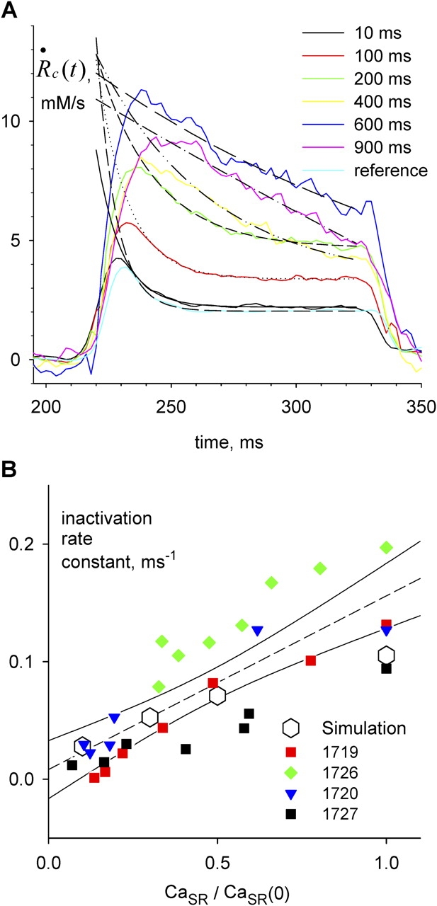
SR depletion slows inactivation. (A)  c
c
 t
t
 transients elicited by test pulses, color coded to conditioning pulse durations. In black traces are superimposed single exponentials, fitted from the beginning of the region with positive curvature, as judged by eye, to the end of the test pulse. Fitted exponential rate constants are plotted vs. fractional SR content in B (red squares). The regression line through these points (not shown) has slope 0.149 ms−1, intercept −0.011 ms−1, and r
2 0.959. Identifier 1719. Removal model parameters had the same values as ID 1726, listed in legend of Fig. 6, except the following, which were adjusted for best fit: [EGTA] = 30 mM, [Parvalbumin] = 1 mM, k
on Ca EGTA = 5.00 μ M−1 s−1, k
off Ca EGTA = 5.00 s−1, maximum pump rate = 10 mM/s, pump dissociation constant for Ca2+ binding = 1.0 μ M. (B) Rate constants from all experiments in Fig. 9 plotted vs. fractional SR content. The dashed line is the linear regression through all the data in the plot, with slope 0.147 ms−1, intercept 0.008 ms−1, and r2 0.639. Open symbols represent rate constants of exponential fits to permeability transients simulated with the model described in discussion, using parameter values given in the legend of Fig. 9.
transients elicited by test pulses, color coded to conditioning pulse durations. In black traces are superimposed single exponentials, fitted from the beginning of the region with positive curvature, as judged by eye, to the end of the test pulse. Fitted exponential rate constants are plotted vs. fractional SR content in B (red squares). The regression line through these points (not shown) has slope 0.149 ms−1, intercept −0.011 ms−1, and r
2 0.959. Identifier 1719. Removal model parameters had the same values as ID 1726, listed in legend of Fig. 6, except the following, which were adjusted for best fit: [EGTA] = 30 mM, [Parvalbumin] = 1 mM, k
on Ca EGTA = 5.00 μ M−1 s−1, k
off Ca EGTA = 5.00 s−1, maximum pump rate = 10 mM/s, pump dissociation constant for Ca2+ binding = 1.0 μ M. (B) Rate constants from all experiments in Fig. 9 plotted vs. fractional SR content. The dashed line is the linear regression through all the data in the plot, with slope 0.147 ms−1, intercept 0.008 ms−1, and r2 0.639. Open symbols represent rate constants of exponential fits to permeability transients simulated with the model described in discussion, using parameter values given in the legend of Fig. 9.
A corrected release flux, which would be produced if the driving force for Ca2+ release, assumed proportional to CaSR(t), remained constant at its initial value, is calculated as
 |
(8) |
where  (u) + pump flux (u) is the net flux leaving the SR (see Eq. 3 in Shirokova et al., 1996).
The ratio of  c(t)and CaSR(0) is a quantity with dimensions of inverse time, which we call release permeability P(t). Strictly, it is the SR permeability multiplied by the SR surface-to-volume ratio and by the ratio of free over bound Ca2+ in the SR (Shirokova et al., 1995). Thus we define
 |
(9) |
In the present work, the total concentration of Ca2+ released was also calculated by a method similar (but not identical) to that of Pape et al. (1995). This method is based on the exchange reaction Ca2+ + H2EGTA2− = CaEGTA2− + 2H+, which occurs rapidly upon increases in [Ca2+] at a rate approximately proportional to Δ[Ca2+] (Pape et al., 1995). In the presence of 36 mM EGTA almost all of the released Ca2+ will be captured by EGTA. Therefore a release per unit volume in the amount of Δ[Ca2+]T will result rapidly and proportionally in an increase Δ[H+]T = 2 Δ[Ca2+]T.
The signal from phenol red can be used to calculate free [H+] (Eq. 3). The change in [H+] is related to release Δ[Ca2+]T by
 |
(10) |
where α is the buffer capacity defined as Δ[H+]T/Δ[H+]. This is a linearly defined capacity, which we use instead of the conventional definition
 |
(11) |
used by Pape et al. (1995). Consequences of this change are presented in the online supplemental material (available at http://www.jgp.org/cgi/content/full/jgp.200409071/DC1).
One difference between these determinations of flux is that the removal method defines  ≲t
≲t
 in a manner suitable to isolate release through channels, as the increase in SR transmembrane flux when the voltage is on (Melzer et al., 1984). In contrast, the rate of change of [H+] is proportional to net trans-SR membrane flux. Therefore, the SERCA pump flux (which is negative if release is positive) is included in this measurement. Specifically
 |
(12) |
According to Eq. 10, the change Δ[H+]max associated to a pulse of voltage and duration sufficient to fully deplete the SR will be equal to (2/α)CaSR(0). This allows one to use the [H+] transient measurement instead of release flux in the correction term of Eq. 8, which then becomes
 |
(13) |
The change in [H+] provides a better measure of total release than the integral of  ≲t
≲t
 for two reasons. First, it is a measure of the net transmembrane flux; additionally, the H+ displacement measures the Ca2+ release “primitive,” rather than its flux, which results as argued later in lower drift or low temporal frequency errors. Therefore Eq. 13 is preferable to 8 for the calculation of permeability. Rates of change are calculated digitally in the time domain by convolution with a 17-point Kaiser kernel, which performs differentiation and low pass filtering at 25% of the sampling frequency (Hamming, 1998).
Online Supplemental Material
The online supplemental material is available at http://www.jgp.org/cgi/content/full/jgp.200409071/DC1. The online supplement explores properties of the H+ buffer in the cytosol. Two alternative definitions of buffering power are compared. It is found that α (Eq. 10) is slightly more constant than β (Eq. 11). The applicability of Eq. 12 is demonstrated, and α is estimated at ∼2 × 10⁴.
RESULTS
Signals from [H+] and [Ca2+] Could Be Obtained Simultaneously
The basic protocol of these experiments was to simultaneously record light signals upon voltage stimulation at three wavelengths in fibers containing 36 mM EGTA, a Ca2+-sensitive dye, and a H+-sensitive dye in their cytosol (ApIII and phenol red, respectively). Raw intensities were then converted to absorbance changes and linearly combined to derive pure signals from the two dyes. The signal from ApIII was used to derive “Ca2+ transients” Δ[Ca2+](t), and that of phenol red yielded [H+](t) as described in materials and methods. There it is also shown that the two measurements can be performed simultaneously, with little mutual interference.
Simultaneous Measurements of Changes in Free Cytosolic and Total SR [Ca2+]
The effect of changing SR Ca2+ content on Ca2+ release was studied with a simple protocol. It consisted of three pulses: a reference pulse to a voltage large enough to elicit a flux waveform with clearly distinct kinetic stages, followed by a depleting pulse of maximally activating amplitude and variable duration, and then a test of the same amplitude and duration as the reference. The test pulse was applied at a fixed interval of 1,100 ms after the end of the depleting pulse. This interval allows for complete recovery from fast inactivation of release. With this protocol the amount of Ca2+ left in the SR was set by the duration of the depleting pulse.
A typical set of records obtained with the basic protocol is shown in Fig. 5. In Fig. 5 A, the increase in [H+] observed during the depolarizing pulse reflects displacement of H+ from EGTA by released Ca2+. During the interval between depleting and test pulses, [H+] decreased, reflecting largely return of H+ to EGTA, plus its extrusion, or sequestration into organelles.
Figure 5.
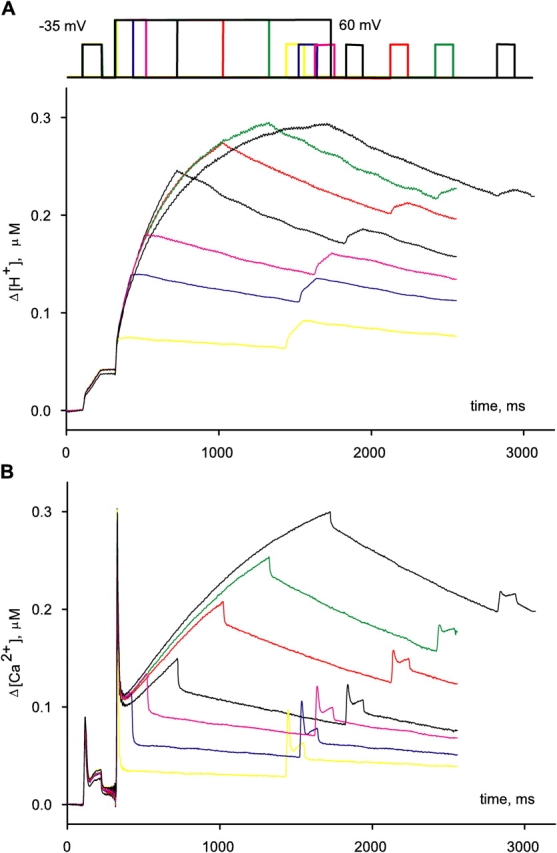
Simultaneously measured Δ[H+](t) and Δ[Ca2+](t). Pulse patterns are represented schematically at top. Different applications, and the corresponding records, are identified by different colors. Pulse protocols consisted of a reference to −35 mV, a conditioning or depleting pulse to 60 mV, of variable duration, and a test, identical to the reference pulse, which followed 1,100 ms after the conditioning pulse. (A) Δ[H+](t), obtained by shifting [H+](t) determined according to Eq. 3. (B) Δ[Ca2+](t), derived from ΔA Ap(720). Identifier 1726, [ApIII] ranged between 0.71 and 1.05 mM. [phenol red], 2.63–3.16 mM. pH 6.65–6.48.
The depleting protocol was repeated at regular 4-min intervals. As shown in Fig. 5 A, the change of [H+] during reference and the initial portion of depleting pulses was the same in all repetitions, indicating that the content of the SR was fully recovered after 4 min. Simultaneously recorded Ca2+ transients derived from ApIII-related absorbance changes, shown in Fig. 5 B, had the typical time course observed in the presence of high [EGTA] in the myoplasm, which is the sum of a term proportional to release flux plus another roughly proportional to its time integral (Pape et al., 1995; Song et al., 1998). Again, reproducible ApIII signals were obtained during reference and depleting pulses.
By contrast, the signals during the test pulse were dramatically modified by conditioning. The amplitude of the [H+] transient elicited by the test pulse became progressively smaller as the depleting pulse duration was increased, and its slope was reduced correspondingly. Equivalent modifications were observed on the ApIII-derived Ca2+ transients.
Two Measures of Ca2+ Release Flux
The time derivative of [H+], illustrated in Fig. 6 A, is proportional to Ca2+ release flux R·≲t) under the assumption that most of the released Ca2+ binds to EGTA (Pape et al., 1995). The constant of proportionality is α/2 (materials and methods, Eq. 10). These waveforms are very similar to those obtained with the removal method of Melzer et al. (1984), shown in Fig. 6 B. While a small quantitative difference is expected between the waveforms (see Eq. 12), both methods report strikingly similar time courses of release flux.
A difference, observed in all experiments, is that the removal method is less affected by high frequency noise. This was expected, both because the derivation of flux from the EGTA/phenol red signal involves differentiation and because the absorption of 575-nm light by ApIII degrades the phenol red signals. In contrast, the flux calculated with the removal method is close to the signal from ApIII without differentiation, because ApIII is in near equilibrium with Ca2+ and, as argued, the evolution of R·≲t) and [Ca2+](t) are close to proportional at high [EGTA]. Therefore the final level of high frequency noise is that of the ApIII signal.
On the other hand, the EGTA/phenol red method gave robust measures of total, or “cumulated” Ca2+ release. By comparison, the corresponding measure using the removal method (the time integral of the flux) was more variable, because it magnifies over time small low frequency errors in the flux waveform. The availability of both measures strengthens their individual reliability and allows one to use each method in the range of frequencies where it excels: the EGTA/phenol red method for the estimates of long term changes in [H+] (hence in SR content) and the removal method for short term kinetics of flux.
SR Ca2+ Content and Permeability
Examination of Ca2+ release after conditioning shows a progressive reduction of flux as the depleting pulse duration is increased. In this regard, it is desirable to separate driving force, i.e., [Ca2+]SR, and Ca2+ release permeability, P, as determinants of the flux. Evaluating the SR Ca2+ content from the measured [H+] transient should be straightforward if a large depletion pulse could totally empty the SR. Assuming constant α, the maximum change in proton concentration (Δ[H+]max) would then be a proportional measure of resting releasable SR content (CaSR, see materials and methods for definition), while the difference between this value and the “running” Δ[H+](t) would be proportional to the current content CaSR(t). The release flux waveform divided by Δ[H+]max − Δ[H+](t) would yield the time course of P (see related Eq. 13).
The analysis proposed above relies heavily on the determination of Δ[H+]max, which should ideally be done with a fully depleting pulse. Full depletion should lead to a steady [H+] during the depleting pulse, as no more Ca2+ would be released and no more protons displaced from EGTA. In most cases, however, even pulses to high positive voltage, of duration >1,500 ms, failed to elicit a constant [H+] level. In all the experiments, the evolution of [H+](t) signals during a depleting pulse could be well fitted, especially after the initial rapid phase of 100 to 200 ms, by a single exponential rise to saturation
 |
(14) |
One of such fits is shown in Fig. 7 A (dashed). According to Eq. 10, the asymptotic value Δ[H+]max multiplied by α/2 is a first approximation to resting CaSR. Hence the corresponding approximation to the time-dependent CaSR is
 |
(15) |
Figure 7.

Correction of release flux for the change in SR Ca content. (A) Δ[H+](t) for the 1,400 ms depleting pulse of the series in Fig. 5. Dashed line, single exponential fit to the record (Eq. 14), from t
0 = 410 ms (50 ms into the pulse) to the end of the depleting pulse, with Δ[H+](t
0) = 0.1219, Δ[H+]max = 0.301, and τ = 0.417 s−1. (α/2)Δ[H+]max is the main term in the quantification of initial SR content (Eq. A3). (B) Release waveform  ≲t
≲t
 (dashed), and
  c
c
 t
t
 calculated according to Eq. A5 (solid). Identifier 1726.
This simple approach to CaSR leads to a small error of underestimation. A steady [H+] only means that the net flux of Ca2+ is zero, that is, release and uptake into the SR are equal. We believe that neither is zero.
Both [H+] and the simultaneously measured Δ[Ca2+] started to decrease immediately after the conditioning pulse (as shown in Fig. 5 B). This decay indicates that H+ returns to EGTA or is extruded from the cell or sequestered into organelles, while Ca2+ is returned to the SR. Because there was proportionality between the changes in [Ca2+] and [H+] (demonstrated in the online supplemental material, available at http://www.jgp.org/cgi/content/full/jgp.200409071/DC1), any losses of displaced H+ toward locations where phenol red was not present were probably proportional to the change in [H+]. Such “leaks” of H+, which alter the stoichiometry between movements of Ca2+ and H+, therefore should not degrade the proportionality between measured Δ[H+] and total displacement of H+ from EGTA. In conclusion, the decay of [H+] after the conditioning pulse should reflect the resequestration rate of Ca2+ into the SR with the same quantitative rules as its increase reflects Ca2+ release. That the initial OFF slope (d[H+]/dt)off was always finite and negative, even after the longest depleting pulses, indicates that the pump was able to resequester Ca2+ at measurable rates, despite the high [EGTA].
The conclusion that a substantial flux of uptake remains after the largest depletion pulses implies that there is a steady flux of release, R·≲∞), when [H+] reaches its steady maximum. Therefore, (α/2) Δ[H+]max cannot be taken as the full measure of SR Ca2+ content. CaSR(∞), the remnant when [H+] stabilizes, must be added. An estimation for this remnant is developed in appendix. Taking it into account, a better estimate of the time-dependent SR content is obtained:
 |
(A4) |
Substituting these estimates of SR content and its initial value in Eq. 13, a better correction formula is derived in appendix, Eq. A5.
The magnitude of CaSR(∞) was small. Δ[H+]max in four experiments is compared with the additional correction term in Table III. In every case, the remnant (in column 5) was a minor fraction, between 2 and 10% of Δ[H+]max (column 2). This additional term did not change the estimated P significantly, except when depletion was almost complete, as was the case at the end of the conditioning pulse illustrated in Fig. 7. In this case, addition of the remnant, ∼10% of CaSR(0), significantly increased the estimated content near the end of the pulse (shown in Fig. 13 and appendix). Because test pulses were always applied 1,100 ms after the conditioning pulse, by then CaSR(t) had recovered, and the effect of the additional term was almost negligible. This is documented in the next three figures, where permeabilities obtained with both Eq. 13, named “first approximation,” and Eq. A5, or “full correction,” are represented together.
TABLE III.
Evaluation of CaSR Remnant After Longest Depleting Pulse
| Identifier | Δ[H+]max | P | −d[H+]/dt | Remnant |
|---|---|---|---|---|
| μM | s−1 | μM s−1 | μM | |
| 1719 | 0.29 | 4.7 | 0.042 | 0.01 |
| 1720 | 0.21 | 6.6 | 0.057 | 0.01 |
| 1726 | 0.3 | 2.4 | 0.091 | 0.029 |
| 1727 | 0.42 | 6.3 | 0.051 | 0.008 |
[H+]max is the asymptotic value of the increase in [H+] at the end of the longest depleting pulse, determined by fitting Eq. 14 to [H+](t) during the last 1 s of the depleting pulse. P is the exponential rate constant of the fit. −d[H+]/dt is (minus) the slope after the end of the depleting pulse (illustrated in Fig. 7 C). “Remnant” is the ratio (d[H+]/dt)/P. CaSR(0) is proportional to Δ[H+]max + remnant.
The simultaneous use of two methods provides two estimates of release flux. R·≲t), represented in dashed trace in Fig.7 B, and the rate of change of [H+], which is approximately proportional to R·≲t) (Eq. 12 and Fig. 13 A). R·≲t) was preferred because of its lower high frequency noise, and corrected according to Eq. A5 to yield the waveform in solid trace, R·c(t), which is proportional to P(t). It reveals a large increase in P near the end of the depleting pulse, an increase that also affects the response to the test pulse, where P is much greater than the reference. This result is consistent with the observation of Pape et al. (1995) of an increase in release permeability upon depletion to ∼70% of CaSR(0). It yields additional information on kinetics, described next. While this is our preferred correction, the alternative “constant permeability” correction method (Schneider et al., 1987b) is considered in detail in a later section.
SR Permeability Was Modified by Depletion in Both Stages of Ca2+ Release
R·≲t) and depletion-corrected R·c(t), derived from the set illustrated in Figs. 6 and 7, are shown in Fig. 8 (A and C) in the time frame of the test pulse. B and D plot their respective peak and steady values as a function of CaSR. Peak and steady levels of release decrease with depletion, but peak does so more rapidly, resulting in a blunted waveform. As clearly shown in Fig. 8 D, peak and steady levels of R·c(t), proportional to SR release permeability, increase with depletion. This increase is clearer for the “steady” value of P. Filled or open symbols in this plot represent, respectively, the values obtained with the first approximation or the full correction. While there are differences, the observations are qualitatively similar for either set. At the greatest levels of depletion, peak P decreases relative to its maximum, reached at ∼0.4 [Ca2+]SR (0).
Figure 8.
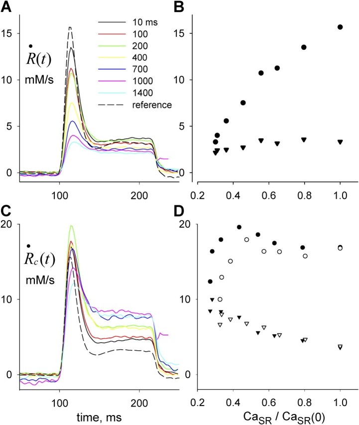
Release permeability changes with SR depletion. (A) Test release flux  ≲t
≲t
 following depleting pulses of various durations, as indicated. (B) Peak (circles) or steady value of level of
  ≲t
≲t
 , vs. CaSR normalized to its resting value. While the peak release flux is roughly proportional to CaSR, the steady value is nearly constant, indicating increase in steady permeability. (C) Corresponding
  c
c
 t
t
 , corrected according to Eq. 13 (“first approximation”). (D) Peak or steady values of
  c
c
 t
t
 , corrected according to Eq. 13 (filled) or Eq. A5 (open symbols). Both corrections yield qualitatively similar dependences. Identifier 1726.
Data from four fibers are shown in Fig. 9. On average, the steady value of permeability increased by a factor of 2.34 as the SR content went from 100 to 25%. Peak P was less sensitive: as CaSR was reduced to 50%, peak P underwent a slight potentiation; it increased more markedly as CaSR was reduced to 30%, and then decreased, in all fibers, with further depletion.
Figure 9.
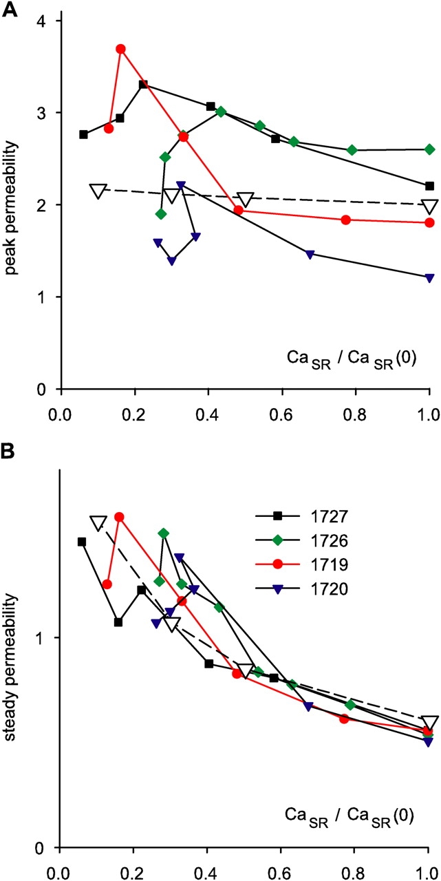
Release permeability and SR content. Peak (A) and steady (B)  c
c
 t
t
 for different degrees of depletion, vs. normalized CaSR. Different symbols represent different experiments. Points are connected by lines in monotonic order of conditioning durations. Correction procedure performed with the lower estimate of SR content (Eq. 15). Peak and steady values of individual experiments were normalized to the average steady value in all realizations of the same experiment. The ordinate is therefore permeability (peak or steady) normalized to average steady permeability. The open symbols plot the outcome of a simulation with the model described in discussion (Eqs. 18, 20, and 22). The simulation generated time courses during a test depolarization to −45 mV at varying degrees of depletion. The activation variable x (Eq. 18) had transition voltage −40 mV, steepness factor 10 mV, and activation rate constant 0.02 ms−1 at the transition voltage. n was set to 8. In Eq. 20, k
f was 1.33 ms−1, k
r was 0.01 ms−1, and K/c
1 was 0.25 for the fully loaded SR, and then scaled in inverse proportion to load, at CaSR = 50%, 30%, and 10% of CaSR(0).
for different degrees of depletion, vs. normalized CaSR. Different symbols represent different experiments. Points are connected by lines in monotonic order of conditioning durations. Correction procedure performed with the lower estimate of SR content (Eq. 15). Peak and steady values of individual experiments were normalized to the average steady value in all realizations of the same experiment. The ordinate is therefore permeability (peak or steady) normalized to average steady permeability. The open symbols plot the outcome of a simulation with the model described in discussion (Eqs. 18, 20, and 22). The simulation generated time courses during a test depolarization to −45 mV at varying degrees of depletion. The activation variable x (Eq. 18) had transition voltage −40 mV, steepness factor 10 mV, and activation rate constant 0.02 ms−1 at the transition voltage. n was set to 8. In Eq. 20, k
f was 1.33 ms−1, k
r was 0.01 ms−1, and K/c
1 was 0.25 for the fully loaded SR, and then scaled in inverse proportion to load, at CaSR = 50%, 30%, and 10% of CaSR(0).
Depletion Changed the Kinetics of Inactivation
As CaSR was reduced by increasing the duration of the depleting pulse, the decay of test P(t) after its peak became progressively slower. As shown in Fig. 10 A, a single exponential fitted well this decay. The rate constant of decay, plotted in Fig. 10 B for the data in A (red) and three other experiments, was found to increase linearly with CaSR. A naive two-state inactivation model, whereby the unidirectional inactivation rate is proportional to CaSR while the opposite transition coefficient is constant, would qualitatively explain the increase in steady permeability, as a consequence of slower inactivation upon increasing depletion. An only slightly more elaborate model, considered later, yielded the quantitative predictions represented with open symbols in Figs. 9 and 10.
The Effects Were Not Due To Changes in Intramembranous Charge Movement
The large pulses used in the protocol could have altered the voltage sensor movements in the test pulse. Intramembranous charge movements were examined in all fibers, and no major change in the charge transferred during the test pulse were found in any experiment. Fig. 11 A shows records of intramembranous charge movements for the reference pulse and for test pulses after the shortest and longest conditioning for the experiment of Figs. 5–8. Slight changes in the kinetics of the current were observed, sometimes resulting in a small change in charge transfer (plotted in Fig. 11 B). An estimation of the effect of this change on release flux is illustrated in Fig. 11 C, which plots the transfer function (González and Ríos, 1993) relating steady release flux to charge transfer, obtained in the same fiber under full SR load. The vertical bars mark charge transfer at the reference voltage, and the value measured after the longest depleting pulse. The corresponding ordinate values show that the increase in charge transfer would account for a 26% increase in steady P. In contrast, steady P increased by >150% in test pulses applied after the longest depleting pulses.
Figure 11.

Changes in intramembranous charge transfer accompanying SR depletion. (A) Intramembranous charge movement currents elicited by the reference pulse to −35 mV (black), or by test pulses to the same voltage, after depleting pulses of 10 ms or 1.4 s. Due to the long conditioning duration, the third record was terminated before completion of the OFF charge movement. (B) Corresponding charge transfer (time integrals Q(t)). (C) “Transfer function,” steady release flux measured from rest (i.e., full SR load) and corrected for depletion vs. Q(V) at the end of a pulse to voltage V. The two dashed vertical lines mark Q(−35 mV) transferred by the reference pulse or the test pulse after depletion. The corresponding values of release flux at these levels of charge are indicated by dashed horizontal lines, which are separated (as shown in the inset with expanded scales) by 26% of the lower value. Release flux should therefore increase by 26% due to the increase in Q. Identifier 1726.
DISCUSSION
Two Techniques Yield Consistent Estimates of Ca2+ Release
A first outcome of the present experiments is that optical absorption measurements of Ca2+ with the rapidly equilibrating dye ApIII, and of associated [H+] transients with phenol red, can be performed together, in the same cell, with minimal interference. Next, it was found that in the presence of 36 mM EGTA, when most released Ca2+ is bound to this buffer and the displaced H+ becomes a proportional measure of net Ca2+ release, both measurements yield consistent determinations of Ca2+ release flux.
The striking agreement between these independent evaluations of flux is illustrated in Fig. 6. The two evaluations, however, should be different by definition. As stated in materials and methods, the time derivative of [H+] in the ideal case of complete capture of released Ca2+ by EGTA is proportional to the net Ca2+ flux entering the cytosol. In contrast, R·≲t) is derived from ApIII absorbance transients as the voltage-dependent flux into the cytosol. They differ by the pump uptake (plus any voltage-independent leaks), terms that are one or two orders of magnitude smaller than the peaks of Ca2+ release but become comparable to the voltage-dependent flux in conditions of high depletion. An example of the difference can be seen comparing the Δ[H+](t) record in Fig. 7 A and the corresponding R·≲t) in Fig. 7 B. While R·≲t) is by definition zero in the intervals at resting potential, d[H+]/dt becomes negative after the pulses, proportional to the pump flux.
Overall, this kinetic similarity is reassuring of the assumptions underlying both methods. One particular concern was the ability of the displacement of H+ from EGTA to follow Ca2+ flux sufficiently rapidly. The proponents of the technique argued that Ca2+ binding to EGTA is a first order reaction, simultaneous with stoichiometric displacement of H+. At high [EGTA], the released Ca2+ is captured very close to release sites. Because [Ca2+] near release sites is proportional to release flux, it follows that the rate of Ca2+ binding to EGTA and production of H+ will be proportional to release flux. The present results support those arguments (Pape et al., 1995).
The removal method to derive Ca2+ release flux also depends on a number of assumptions. The method relies on a fit to OFF portions of the Ca2+ transients, using a model of Ca2+ removal. Therefore, its results will depend on the assumed structure of the model, and of course the values of its parameters. In spite of this inherent model dependence, it has been argued that the waveforms will be kinetically correct even if the parameters have little physical meaning, provided that the fit is good (Schneider et al., 1987a). The present results support these arguments as well.
Under conditions of high [EGTA], fitting the removal model becomes a simple fit of kinetic constants and actual concentration of EGTA. It is interesting that the OFF rate constant obtained in the fit is greater, by ∼10-fold, than the values reported in cuvette. This observation, first communicated by González and Ríos (1993), was confirmed by Schuhmeier et al. (2003) and Schuhmeier and Melzer (2004) for transients in mammalian adult cells and embryonic cells in culture.
Other differences were pointed out in results. While the removal method starts from a signal of free Ca2+, already similar in time dependence to release flux, the phenol red signal originally tracks total Ca2+ increase in the cytosol, and must be differentiated to produce flux records. This results in greater noise of high frequency. Conversely, the estimate of total release provided by EGTA/phenol red is superior, both because it avoids an integration step (which will increase the weight of any error in the late stages of R·≲t)) and because it depends on a single parameter, α, the H+ buffering power of the cytosol. The greater noise of the phenol red records upon differentiation was due in part to the simultaneous presence of ApIII, which absorbed a significant fraction of the 575-nm light carrying the [H+] signal.
A Large Conditioning Depolarization Set Ca2+ in the SR
The three-pulse protocol was designed to reduce CaSR in a controlled manner. Variations of this protocol have been used before in many studies. While in principle the intervening pulse might have multiple effects, these have been explained as resulting mainly from two processes, a rapid inactivation at the level of the release channels, which alters release kinetics (Schneider and Simon, 1988) and depletion of SR content, which scales down the release waveform (Schneider et al., 1987b). The conditioning pulse could in principle also cause inactivation of the T membrane voltage sensor, but this can be measured as charge interconversion (Brum and Ríos, 1987), requires at least 2 s to develop to any measurable extent (Brum et al., 1988), and in the present experiments did not result in significant changes of charge transfer (as shown with Fig. 11).
Additionally, the conditioning depolarization also caused acidification, by up to 0.3 pH units, which in different experiments corresponded to a 200–400 nM change in [H+]. These changes are not significantly greater than those reported by Pape et al. (1995) upon application of trains of action potentials or long-lasting voltage clamp depolarizations, in spite of the fact that the present experiments used a greater [EGTA] (36 instead of 20 mM) and a lower concentration of the pH buffer HEPES (2.8 instead of 10 mM). Technical differences notwithstanding, we did not expect a pH change significantly greater than that reported by Pape et al. (1995). Indeed, at 20 mM, EGTA already captures >95% of the released Ca2+ (Pape et al., 1995), therefore the greater [EGTA] used here should not increase the displacement of H+ by much. Additionally, the buffer power provided by HEPES, defined as the ratio of buffer-bound over free [H+], varied between 0.2 and 1.4 × 10³ (depending on pH), while an approximate calculation of the total buffering power of the cell, presented in Fig. S2 (available at http://www.jgp.org/cgi/content/full/jgp.200409071/DC1), puts it at 2 to 4 × 10⁴, which makes the contribution by extrinsic buffers insignificant. Pape et al. (1995) argued that the pH changes associated with the EGTA/phenol red technique should not affect Ca2+ release significantly. In the present application, the conclusion seems to apply. Indeed, there was no correlation between release kinetics and the initial pH recorded in these experiments, which varied between 6.32 and 6.97. Moreover, as documented in Fig. 6, the responses were reproducible in the lapse of individual experiments, when pH drifted steadily to lower values by up to 0.3 units.
In the removal analysis leading to our Ca2+ release flux records, the rate constants of Ca2+ binding to EGTA determine the result to a great extent, given the dominant role of EGTA in the removal of Ca2+. If the changes in pH modified the properties of EGTA, errors would be introduced in the calculation of release. We do not believe that this was the case, because of the reproducibility of the Ca2+ transients (which would have varied if EGTA changed its properties in the course of an experiment) and because the fitted rate constants of EGTA did not change with initial pH in a consistent manner.
Taking advantage of the fact that inactivation recovers fully in <900 ms (Schneider et al., 1987b), in the present application, the test pulse was positioned at a fixed interval of 1,100 ms after the end of the depleting pulse. Therefore, with this protocol, the duration of the depleting pulse set the amount of Ca2+ left in the SR, presumably without directly changing the gating properties of the release machinery or those of the dominant buffers. Accordingly, the observed changes in release kinetics were interpreted as consequences of the controlled depletion.
Two Kinetic Stages of Ca2+ Release Flux Are Altered by Changes in Intra-SR [Ca2+]
When CaSR was reduced, the steady phase of release flux was reduced in a less than proportional measure, indicating an increase in release permeability.1 This was quantified in the waveform R·≲t) of release flux corrected to constant Ca content of the SR, which is proportional to SR release permeability. The steady P during a test pulse increased gradually as SR content was decreased, reaching ∼2.5-fold increase upon depletion to 25% of the resting load. Pape and Carrier (1998) reported that P(t) elicited by clamp pulses of −70 to −60 mV, which was always devoid of kinetic peak, remained nearly unchanged as CaSR was reduced to 50% of CaSR(0), and then increased fivefold when the SR was depleted to 20%. The present results are similar qualitatively, but the effect was smaller here. Although we found effects in the whole depletion range, they also seemed more pronounced when CaSR fell below 50% of CaSR(0).
The peak of P was affected much less than its steady value. It increased ∼30% at 20% of CaSR(0). At lower SR loads, peak release permeability decayed from its maximum to a variable degree, as shown in Fig. 9. Pape et al. (1998) found that (CaSR-normalized) peak release flux elicited either by an action potential or by a short pulse to 0 mV, behaved very much as peak P in our study. Pape et al. (2002) reported that peak P elicited by a depolarization to −45 mV was resistant to depletion up to 30% of CaSR(0), and then decreased at lesser SR content. In summary, the present results and analysis are qualitatively consistent with earlier conclusions of the group that introduced the EGTA/phenol red technique (Pape et al., 1995, 1998, 2002), but yield quantitatively lesser effects of depletion on permeability. By contrast, it is difficult to reconcile these results with another established method of correction, considered in the next section.
The Present Results Are Inconsistent with the “Constant Permeability” Assumption
An alternative method to correct for the decaying driving force during Ca2+ release, introduced by Schneider et al. (1987b), essentially inverts the terms of the problem, starting from the notion that permeability becomes constant, dependent on voltage but not on SR content, after the fast inactivation ends. The procedure, which has been used repeatedly by us and other laboratories, starts from a simplified version of Eq. 8,
 |
(16) |
and attempts to find a value for CaSR (0) such that the corrected flux R·c(t) becomes constant after the peak.
For the present illustration, the method was applied to the example R·≲t) records of Fig. 6. For every record where the conditioning pulse had a sufficiently long duration, it was possible to find a value of CaSR (0) that led to an approximately constant value of R·c(t) late during the conditioning pulse. This is illustrated in Fig. 12 for the release record plotted in Fig. 7 B. In blue is R·≲t). In red is R·c(t) calculated according to Eq. 16, with CaSR (0) = 14.5 mM. It can be seen that the test portion of the corrected record has a much greater steady level than the reference. The constant permeability assumption, therefore, leads to an internal contradiction that the corrected level (i.e., permeability) of the −35-mV test is much greater than the reference obtained at the same voltage before depletion.
Figure 12.
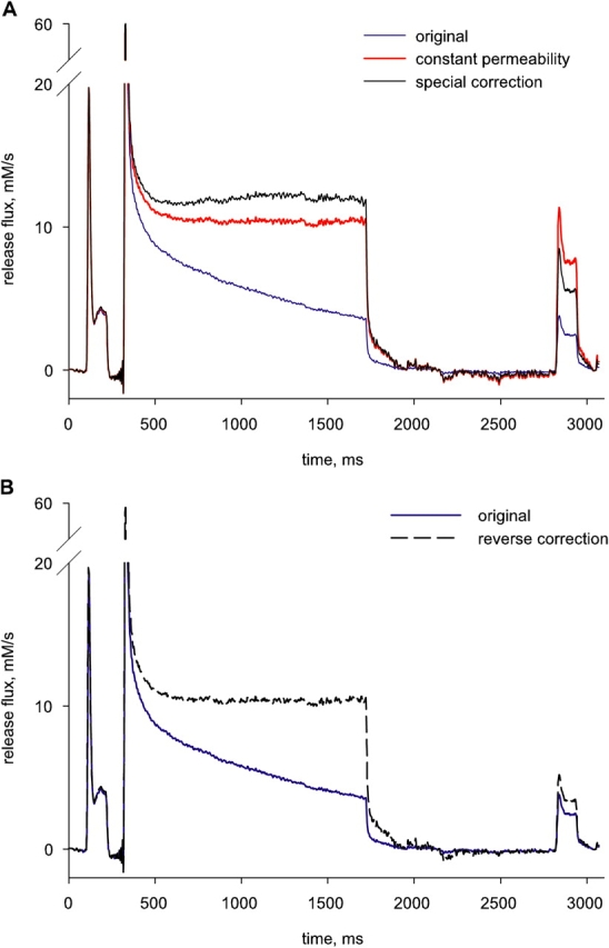
The “constant permeability” correction. (A) Blue trace:  ≲t
≲t
 , same as in Fig. 7 B. Red:
  c
c
 t
t
 , calculated according to Eq. 16. The choice of the value 14.5 mM for CaSR(0) led to a nearly constant corrected level during late portions of the conditioning pulse. Black: correction according to Eq. 17, with CaSR(0) = 11.5 mM and pump flux computed from the removal model, with best fit parameters given in the legend of Fig. 6. (B) Blue trace:
  ≲t
≲t
 , repeated from A. “Reverse correction” (black dashed) is obtained with Eq. 17, by increasing the term “pump flux” during the interval between conditioning and test, which increases the denominator in Eq. 17, until the corrected test release flux reaches the same steady level as the reference release flux (in accordance with the constant permeability hypothesis). An implausibly large 67% of the amount released during the conditioning pulse must return in order to reach this level.
A fair application of the constant permeability method requires the integration of net, rather than voltage-dependent, Ca2+ flux to compute CaSR(t). The difference is the pump flux, which must be added in the integrand of Eq. 16 to yield 17:
 |
(17) |
which is the same as Eq. 8.
Release and pump flux have opposite signs. If pump flux was substantial, its omission would lead to underestimating the SR content at the time of the test, hence yielding an erroneous increase in permeability. Pump flux is not known in general, but it can be approximated by the pump term in the removal model that leads to R·≲t). The constant permeability correction can be modified so that the corrected flux, generated by Eq. 17, reaches a constant value. Such technique, applied to the release flux record of Fig. 12, yielded the record in black (labeled “special correction”). Calculated this way, test permeability again was greater than reference.
In a third attempt to reconcile data with the constant permeability hypothesis, we tried a reverse approach, asking how much Ca2+ should have returned to the SR in the interval between conditioning and test pulses to explain the observed release flux without a permeability change. The answer is 6.25 mM, or 67% of the amount released by the conditioning pulse. A corrected release under such assumption is illustrated (as “reverse correction”) in Fig. 12 B, which also has the original release flux.
Clearly, that much could not have returned during the interpulse. The recovery of SR content takes many seconds (for example see Fig. 2 B of Schneider et al., 1987b). Here, where the SERCA pump must work at the very low [Ca2+]cyto set by the high concentration of EGTA, recovery should be even slower. One way or another, the constant permeability assumption leads to contradictions.
In conclusion, the constant permeability hypothesis cannot account for the present observations. It is worth noting, however, that the procedure has been used mostly for the correction of brief transients. In the present work, the increase in P during the high voltage pulses became noticeable only after the first 200 ms of the pulses. By then the SR content had dropped to <70% of its resting value. The constant permeability analysis should be valid within those bounds of CaSR.
While the present results confirm that release permeability increases upon depletion of the SR, they fail to reproduce the very large changes in P reported in previous work (e.g., Fénélon and Pape, 2002). One reason is that the previous studies usually reached greater degrees of depletion than those achieved here. The increased depletion may have caused a greater effect, but an overestimation of the depletion (i.e., underestimation of CaSR) would have exaggerated the increase in permeability. No provision for a remnant term, as in our Eq. A4, was made in the work cited. At the high degrees of depletion reached at the end of the pulses used by Fénélon and Pape (2002) to evaluate CaSR(0), the remnant could amount to a substantial fraction. Its omission would have overstated the value of P.
Ca2+-dependent Inactivation Must Operate at a Cytosolic, Rather Than Lumenal, Site
The present work provides additionally a glimpse of the transition from peak to steady permeability, showing that the first order rate constant of this inactivation is made slower by SR depletion, and that the relationship between SR content and inactivation rate is close to a direct proportionality (Fig. 10 B). An approximately linear dependence between inactivation rate and SR content immediately points at Ca2+ as driver of the inactivation process. That peak is affected less than steady P suggests that the channels must open for the effect to develop. In this view, the channels open first, rapidly reaching peak SR permeability before the effect on permeability develops. This is consistent with a cytosolic rather than SR-lumenal site of Ca2+-dependent inactivation. Any alternative explanation based on lumenal actions would have to include ad-hoc provisions to explain the resilience of the peak. Additionally, the simple proportionality between [Ca2+]SR and inactivation rate is explained naturally assuming a cytosolic Ca2+ target.
Most features of the effect can be modeled as secondary to the decrease in inactivation rate, if binding of Ca2+ to cytosolic sites inactivates release channels. We tested these ideas with an implementation by Jong et al. (1995) of the inactivation model of Schneider and Simon (1988).
In this implementation, the release channels, assumed all identical, have their open probability expressed by the product of activation and availability factors:
 |
(18) |
The first order activation variable a, which varies from 0 to 1, with 1 corresponding to the fully activated channel, is determined by membrane voltage acting on the voltage sensors of the T tubule, and is equated in this application to x(t)n, a first order Hodgkin and Huxley variable raised to a power (n = 8) suitable to reproduce the time course of release activation:
The inactivation process determines open probability through the availability b, the fraction of channels that are not inactivated. The evolution of b, which also varies between 0 and 1, depends on binding of Ca2+ to a receptor R on the channel, as represented in the diagram. Ca2+ binds to R in a fast reaction of dissociation constant K, to yield the complex “Ca R,” which may then undergo a first order conformational change with rate constants k f and k r to an inactivated state Ca R*. K, k f, and k r are assumed to be constant (independent of voltage and [Ca2+]).
Let CaR and R represent the fraction of channels in noninactivated states CaR and R, then b, which is the sum of CaR plus R, evolves according to
 |
(19) |
Eq. 19 can be rewritten as
 |
(20) |
When [Ca2+], the concentration of calcium sensed by the inactivation site, is nearly constant, then k app becomes approximately constant, implying that the evolution of b(t) will be approximately exponential.
The release permeability P(t) derived in the present experiments should evolve proportionally to the fraction of open channels, f(t). Hence the model succeeds in explaining the quasi-exponential time courses illustrated in Fig. 10.
Moreover, in the conditions of the present experiments, the presence of high concentrations of EGTA determines a rapid spatial decay of calcium concentration near open channels. The local increase in [Ca2+] will be proportional to the SR release flux (Ríos and Pizarro, 1991; Jong et al., 1995), which in turn should be proportional to the fraction of open channels f(t). Because these changes are expected to be much greater than the resting cytosolic concentration, the local [Ca2+] sensed at the inactivation site will be approximately proportional to f:
 |
(21) |
and the apparent first order rate constant of inactivation,
 |
(22) |
Eqs. 19–22 are restatements of Eqs. 2–8 of Jong et al. (1995). c 1 depends on the intensity of the source (i.e., the single channel current). Assuming a proportional dependence of unitary current on SR content, f(t) was simulated at different degrees of depletion simply by including CaSR(t)/CaSR(0) as a factor in c 1, and numerically solving differential Eq. 20, together with 18 and 22. The normalized P was derived from f and compared with the experimental values.
The open triangles in both panels of Fig. 9 represent values of peak and steady P obtained with this model (at Vm = −45 mV). In Fig. 10, the open symbols represent the rates of inactivation, from exponential fits to simulated f(t), showing a reasonable reproduction of the dependence of inactivation rate with SR content.
This model relies on multiple simplifications and is not meant to provide accurate simulations. Likewise, it cannot be claimed to be unique, as other models could conceivably reproduce the observations. It is, however, parsimonious, in the sense that it uses a prevailing view of Ca2+-dependent inactivation and the simple expectation that local [Ca2+] should be linked to release flux. The fact that it reproduces, albeit roughly, the depletion dependence of both peak and steady phases of release, as well as the effects on kinetics of decay, suggests that this simple concept captures essential aspects of the underlying mechanism.
The decay of peak permeability observed in some fibers with further reduction in SR content is consistent with “CICR”, a role of Ca2+ in channel activation (Fabiato, 1984; Ríos and Pizarro, 1988; Jacquemond et al., 1991; Pape and Carrier, 1998). That the effect was observed at very low CaSR is consistent with evidence that CICR requires lower [Ca2+] than inactivation. At these high levels of depletion, it is difficult to evaluate CaSR with accuracy, and an artifactual reason for the decay in peak P cannot be ruled out. Caveats aside, the idea that CICR contributes to release in frog muscle, and that this contribution is particularly important for the peak, is supported by many other lines of evidence.
The most solid conclusions from the present work, however, are two others. One is that both “removal” and “EGTA/phenol red” yield reliable pictures of Ca2+ release kinetics, and work well together. The other is that Ca2+ content in the SR determines kinetics of release flux and the transition into inactivation through a cytosolic effect of released Ca2+. This mechanism was first suggested by Baylor et al. (1983), later formalized by Schneider and Simon (1988), and then supported through many studies (Baylor and Hollingworth, 1988; Simon et al., 1991; Jong et al., 1995; Pape et al., 1998; Rengifo et al., 2002). Intriguing questions that remain are how this mechanism translates to the gating of single channels in situ, and how it is reflected in the magnitude and kinetics of Ca2+ sparks.
(SCHEME 1).

Supplemental Material
Acknowledgments
This work was supported by grants AR32808 and AR049184 from the National Institute of Arthritis and Musculoskeletal and Skin Diseases, National Institutes of Health.
Olaf S. Andersen served as editor.
APPENDIX
An Additional Term in the Correction of Ca2+ Release to Constant SR Ca2+ Content
The purpose of this appendix is to fully describe our preferred estimation of the time-dependent CaSR. As done by Pape et al. (1995) it computes CaSR(t) as proportional to the difference between the maximum measured change in [H+] and its time varying measure, but adds a constant term, the remnant after the longest depleting pulse.
The first approximation developed in the body of the paper, leading to Eq. 15, uses as estimate of CaSR (0) (the resting content), a value proportional to the asymptote of an exponential fitted to the evolution of [H+](t) in a prolonged depleting pulse. As stated before, prolonged depleting pulses lead eventually to a maximal, constant [H+] in the cytosol, which is a necessary condition to assure that the SR has been fully depleted. A steady [H+], however, only means that the net flux of Ca2+ is zero, that is, Ca2+ release and uptake into the SR are equal. The decay of [H+] after the pulse is turned off indicates the return of H+ to EGTA as its binding sites are freed from Ca2+. H+ may also be extruded from the cell, or taken into organelles, but given the narrow range of its concentration changes, the fluxes to and from other compartments should be proportional to Δ[H+]. Given its large concentration, EGTA should be the main sink for H+ ions as [Ca2+] dissociates after the pulse. Therefore, the evolution of [H+](t) should reflect the net Ca2+ flux into the cytosol during a pulse, as well as out of it and into the SR, when release stops. This is illustrated further in the online supplemental material (available at http://www.jgp.org/cgi/content/full/jgp.200409071/DC1), where Fig. S1 demonstrates a rough proportionality between Δ[Ca2+](t) and Δ[H+](t). Fig. 13 A plots the time derivative of the record [H+](t) in Fig. 7. That the OFF slope of [H+](t) was always finite and negative, even after the longest depleting pulses, evidences a measurable resequestration Ca2+ flux.
Figure 13.

Ca2+ remnant in the SR after the longest pulses. (A) Time derivative of Δ[H+](t) from the record in Fig. 7 A. Inset is same record at an expanded scale, to illustrate evolution at end of conditioning pulse. Horizontal bar in inset plots (d[H+]/dt)off, average over 100 ms following the end of the conditioning pulse. This value is used in Eqs. A2–A5. (B) Two estimates of CaSR(t). Black trace: (α/2)CaSR(t) according to Eq. 15. Red: (α/2)CaSR(t) according to Eq. A4. The estimates of CaSR(t) differ by a constant, the remnant CaSR(∞). (C) Release flux and its correction. Blue trace:  ≲t
≲t
 calculated by the removal method (same record as in Fig. 7 B). Black:
  c
c
 t
t
 , derived from
  ≲t
≲t
 by Eq. 13 (the “first approximation”). Red:
  c
c
 t
t
 from Eq. A5 (the “full correction”). Note that the two corrected records differ greatly at the end of the conditioning pulse, but not so during the test pulse. Identifier 1726.
That a substantial flux of uptake remains after the largest depletion pulses implies that there is a steady flux of release, R·≲∞), when [H+] reaches its steady maximum. CaSR (∞), the remnant in the SR when [H+] stabilizes, must be added to (α/2) Δ[H+]max.
The remnant Ca2+ cannot be measured by H+ displacement because it is by definition what is left after H+ displacement ends. However, the flux of removal can (as it should be proportional to d[H+]/dt at the OFF), and it should be equal and opposite to R·≲∞). According to Eq. 9,
 |
(A1) |
As shown in Fig. 7 A, [H+](t) can be well fitted by an exponential rise. This implies that [Ca2+] is equilibrating between two compartments through a membrane of approximately constant permeability. If this is the case, then 1/τ will equal P (a magnitude defined in the text, proportional to SR membrane permeability). The exponential thus affords an approximate estimate of permeability, and therefore of remnant CaSR at the end of the depleting pulse.
In sum, the remnant content satisfies the equation
 |
(A2) |
To reduce noise, d[H+]/dt was averaged during 100 ms after the end of the pulse (level illustrated by the bar in the inset of Fig. 13 A). The total content CaSR(0) therefore follows
 |
(A3) |
This can be inserted in Eq. 15 instead of Δ[H+]max, to obtain an improved estimate of the time-dependent (2/α) CaSR(t).
 |
(A4) |
Substituting this estimate, the correction formula 13 becomes
 |
(A5) |
The estimate of SR content provided by Eq. A4 is plotted in red in Fig. 13 B. The trace in black represents the SR content calculated by Eq. 15. The relative importance of the remnant is of course dependent on the value of CaSR(t). This is illustrated in Fig. 13 C comparing the original R·≲t) with R·c(t) corrected according to Eq. A5 (red) and the same correction, but using Eq. 13 (black). The large increase in R·c(t) in the black record at the end of the depleting pulse reflects a very small denominator in Eq. 13. Even after inclusion of the remnant, the corrected flux (red) increases greatly. Any errors in the estimation of the remnant (errors in the exponential fit, or in the measured slope, see Eq. A2) will affect the corrected release, hence the estimated permeability, disproportionately more at the time when depletion is greatest. Inclusion of this remnant in the estimate of CaSR(t) did not result in major changes of the corrected release flux during the test pulse. This should be clear from examination of Fig. 13, and especially Table III, where the magnitude of the remnant is seen to be smaller in the experiments not illustrated.
Abbreviations used in this paper: CICR, Ca2+-induced Ca2+ release; SR, sarcoplasmic reticulum; T, transverse.
Footnotes
This conclusion is inconsistent with the exponential fit analysis illustrated in Fig. 7 A, which implies a constant P. To clarify this issue, we fitted exponentials to separate sections of the depletion transient [H+](t), and found different rate constants. In the example shown, the rate constant of the fit to the entire transient was 2.4 s−1, while for the last 450 ms it was 3.5 s−1. The fits indicate an increase in permeability with increasing depletion, and are therefore in agreement with the time course of the corrected release waveform.
References
- Baylor, S.M., and S. Hollingworth. 1988. Fura-2 calcium transients in frog skeletal muscle fibres. J. Physiol. 403:151–192. [DOI] [PMC free article] [PubMed] [Google Scholar]
- Baylor, S.M., and S. Hollingworth. 1990. Absorbance signals from resting frog skeletal muscle fibers injected with the pH indicator dye, phenol red. J. Gen. Physiol. 96:449–471. [DOI] [PMC free article] [PubMed] [Google Scholar]
- Baylor, S.M., W.K. Chandler, and M.W. Marshall. 1983. Sarcoplasmic reticulum calcium release in frog skeletal muscle fibres estimated from Arsenazo III calcium transients. J. Physiol. 344:625–666. [DOI] [PMC free article] [PubMed] [Google Scholar]
- Brum, G., and E. Ríos. 1987. Intramembrane charge movement in frog skeletal muscle fibres. Properties of charge 2. J. Physiol. 387:489–517. [DOI] [PMC free article] [PubMed] [Google Scholar]
- Brum, G., R. Fitts, G. Pizarro, and E. Ríos. 1988. Voltage sensors of the frog skeletal muscle membrane require calcium to function in excitation-contraction coupling. J. Physiol. 398:475–505. [DOI] [PMC free article] [PubMed] [Google Scholar]
- Csernoch, L., V. Jacquemond, and M.F. Schneider. 1993. Microinjection of strong calcium buffers suppresses the peak of calcium release during depolarization in frog skeletal muscle fibers. J. Gen. Physiol. 101:297–333. [DOI] [PMC free article] [PubMed] [Google Scholar]
- Donoso, P., H. Prieto, and C. Hidalgo. 1995. Luminal calcium regulates calcium release in triads isolated from frog and rabbit skeletal muscle. Biophys. J. 68:507–515. [DOI] [PMC free article] [PubMed] [Google Scholar]
- Fabiato, A. 1984. Dependence of calcium-induced release from the sarcoplasmic reticulum of skinned skeletal muscle fibres from the frog semitendinosus on the rate of change of free Ca2+ at the outer surface of the sarcoplasmic reticulum. J. Physiol. 353:56P. [Google Scholar]
- Fénélon, K., and P.C. Pape. 2002. Recruitment of Ca2+ release channels by calcium-induced Ca2+ release does not appear to occur in isolated Ca2+ release sites in frog skeletal muscle. J. Physiol. 544:777–791. [DOI] [PMC free article] [PubMed] [Google Scholar]
- Francini, F., and E. Stefani. 1989. Decay of the slow calcium current in twitch muscle fibers of the frog is influenced by intracellular EGTA. J. Gen. Physiol. 94:953–969. [DOI] [PMC free article] [PubMed] [Google Scholar]
- González, A., and E. Ríos. 1993. Perchlorate enhances transmission in skeletal muscle excitation-contraction coupling. J. Gen. Physiol. 102:373–421. [DOI] [PMC free article] [PubMed] [Google Scholar]
- Gyorke, S., I. Gyorke, V. Lukyanenko, D. Terentyev, S. Viatchenko-Karpinski, and T.F. Wiesner. 2002. Regulation of sarcoplasmic reticulum calcium release by luminal calcium in cardiac muscle. Front. Biosci. 7:d1454–d1463. [DOI] [PubMed] [Google Scholar]
- Hamming, R.W. 1998. Digital Filters. 3rd ed. Dover Publications Inc., Mineola, NY. 196–200.
- Hollingworth, S., A.B. Harkins, N. Kurebayashi, M. Konishi, and S.M. Baylor. 1992. Excitation-contraction coupling in intact frog skeletal muscle fibers injected with mmolar concentrations of fura-2. Biophys. J. 63:224–234. [DOI] [PMC free article] [PubMed] [Google Scholar]
- Ikemoto, N., M. Ronjat, L.G. Meszaros, and M. Koshita. 1989. Postulated role of calsequestrin in the regulation of calcium release from sarcoplasmic reticulum. Biochemistry. 28:6764–6771. [DOI] [PubMed] [Google Scholar]
- Jacquemond, V., L. Csernoch, M.G. Klein, and M.F. Schneider. 1991. Voltage-gated and calcium-gated calcium release during depolarization of skeletal muscle fibers. Biophys. J. 60:867–873. [DOI] [PMC free article] [PubMed] [Google Scholar]
- Jong, D.S., P.C. Pape, S.M. Baylor, and W.K. Chandler. 1995. Calcium inactivation of calcium release in frog cut muscle fibers that contain millimolar EGTA or Fura-2. J. Gen. Physiol. 106:337–388. [DOI] [PMC free article] [PubMed] [Google Scholar]
- Kovacs, L., E. Ríos, and M.F. Schneider. 1983. Measurement and modification of free calcium transients in frog skeletal muscle fibres by a metallochromic indicator dye. J. Physiol. 343:161–196. [DOI] [PMC free article] [PubMed] [Google Scholar]
- Laver, D.R., T.M. Baynes, and A.F. Dulhunty. 1997. Magnesium inhibition of ryanodine-receptor calcium channels: evidence for two independent mechanisms. J. Membr. Biol. 156:213–229. [DOI] [PubMed] [Google Scholar]
- Maylie, J., M. Irving, N.L. Sizto, and W.K. Chandler. 1987. a. Calcium signals recorded from cut frog twitch fibers containing antipyrylazo III. J. Gen. Physiol. 89:83–143. [DOI] [PMC free article] [PubMed] [Google Scholar]
- Maylie, J., M. Irving, N.L. Sizto, G. Boyarsky, and W.K. Chandler. 1987. b. Calcium signals recorded from cut frog twitch fibers containing tetramethylmurexide. J. Gen. Physiol. 89:145–176. [DOI] [PMC free article] [PubMed] [Google Scholar]
- Melzer, W., E. Ríos, and M.F. Schneider. 1984. Time course of calcium release and removal in skeletal muscle fibers. Biophys. J. 45:637–641. [DOI] [PMC free article] [PubMed] [Google Scholar]
- Melzer, W., E. Ríos, and M.F. Schneider. 1987. A general procedure for determining the rate of calcium release from the sarcoplasmic reticulum in skeletal muscle fibers. Biophys. J. 51:849–863. [DOI] [PMC free article] [PubMed] [Google Scholar]
- Pape, P.C., and N. Carrier. 1998. Effect of sarcoplasmic reticulum (SR) calcium content on SR calcium release elicited by small voltage-clamp depolarizations in frog cut skeletal muscle fibers equilibrated with 20 mM EGTA. J. Gen. Physiol. 112:161–179. [DOI] [PMC free article] [PubMed] [Google Scholar]
- Pape, P.C., and N. Carrier. 2002. Calcium release and intramembranous charge movement in frog skeletal muscle fibres with reduced (<250 microM) calcium content. J. Physiol. 539:253–266. [DOI] [PMC free article] [PubMed] [Google Scholar]
- Pape, P.C., D.S. Jong, and W.K. Chandler. 1995. Calcium release and its voltage dependence in frog cut muscle fibers equilibrated with 20 mM EGTA. J. Gen. Physiol. 106:259–336. [DOI] [PMC free article] [PubMed] [Google Scholar]
- Pape, P.C., D.S. Jong, and W.K. Chandler. 1998. Effects of partial sarcoplasmic reticulum calcium depletion on calcium release in frog cut muscle fibers equilibrated with 20 mM EGTA. J. Gen. Physiol. 112:263–295. [DOI] [PMC free article] [PubMed] [Google Scholar]
- Pape, P.C., K. Fénélon, and N. Carrier. 2002. Extra activation component of calcium release in frog muscle fibres. J. Physiol. 542:867–886. [DOI] [PMC free article] [PubMed] [Google Scholar]
- Rengifo, J., R. Rosales, A. González, H. Cheng, M.D. Stern, and E. Ríos. 2002. Intracellular Ca2+ release as irreversible Markov process. Biophys. J. 83:2511–2521. [DOI] [PMC free article] [PubMed] [Google Scholar]
- Ríos, E., and G. Pizarro. 1988. Voltage sensors and calcium channels of excitation-contraction coupling. News Physiol. Sci. 3:223–227. [Google Scholar]
- Ríos, E., and G. Pizarro. 1991. Voltage sensor of excitation-contraction coupling in skeletal muscle. Physiol. Rev. 71:849–908. [DOI] [PubMed] [Google Scholar]
- Ríos, E., and M.F. Schneider. 1981. Stoichiometry of the reactions of calcium with the metallochromic indicator dyes antipyrylazo III and arsenazo III. Biophys. J. 36:607–621. [DOI] [PMC free article] [PubMed] [Google Scholar]
- Schneider, M.F., and B.J. Simon. 1988. Inactivation of calcium release from the sarcoplasmic reticulum in frog skeletal muscle. J. Physiol. 405:727–745. [DOI] [PMC free article] [PubMed] [Google Scholar]
- Schneider, M.F., E. Ríos, and W. Melzer. 1987. a. Determining the rate of calcium release from the sarcoplasmic reticulum in muscle fibers. Biophys. J. 51:1005–1007. [DOI] [PMC free article] [PubMed] [Google Scholar]
- Schneider, M.F., B.J. Simon, and G. Szucs. 1987. b. Depletion of calcium from the sarcoplasmic reticulum during calcium release in frog skeletal muscle. J. Physiol. 392:167–192. [DOI] [PMC free article] [PubMed] [Google Scholar]
- Schuhmeier, R.P., and W. Melzer. 2004. Voltage-dependent Ca2+ fluxes in skeletal myotubes determined using a removal model analysis. J. Gen. Physiol. 123:33–51. [DOI] [PMC free article] [PubMed] [Google Scholar]
- Schuhmeier, R.P., B. Dietze, D. Ursu, F. Lehmann-Horn, and W. Melzer. 2003. Voltage-activated calcium signals in myotubes loaded with high concentrations of EGTA. Biophys. J. 84:1065–1078. [DOI] [PMC free article] [PubMed] [Google Scholar]
- Shirokova, N., A. González, J. Ma, R. Shirokov, and E. Ríos. 1995. Properties and roles of an intramembranous charge mobilized at high voltages in frog skeletal muscle. J. Physiol. 486:385–400. [DOI] [PMC free article] [PubMed] [Google Scholar]
- Shirokova, N., J. García, G. Pizarro, and E. Ríos. 1996. Ca2+ release from the sarcoplasmic reticulum compared in amphibian and mammalian skeletal muscle. J. Gen. Physiol. 107:1–18. [DOI] [PMC free article] [PubMed] [Google Scholar]
- Simon, B.J., M.G. Klein, and M.F. Schneider. 1991. Calcium dependence of inactivation of calcium release from the sarcoplasmic reticulum in skeletal muscle fibers. J. Gen. Physiol. 97:437–471. [DOI] [PMC free article] [PubMed] [Google Scholar]
- Smith, P.D., G.W. Liesegang, R.L. Berger, G. Czerlinski, and R.J. Podolsky. 1984. A stopped-flow investigation of calcium ion binding by ethylene glycol bis(beta-aminoethyl ether)-N,N'-tetraacetic acid. Anal. Biochem. 143:188–195. [DOI] [PubMed] [Google Scholar]
- Song, L.S., J.S. Sham, M.D. Stern, E.G. Lakatta, and H. Cheng. 1998. Direct measurement of SR release flux by tracking ‘Ca2+ spikes’ in rat cardiac myocytes. J. Physiol. 512:677–691. [DOI] [PMC free article] [PubMed] [Google Scholar]
- Stern, M.D., G. Pizarro, and E. Ríos. 1997. Local control model of excitation–contraction coupling in skeletal muscle. J. Gen. Physiol. 110:415–440. [DOI] [PMC free article] [PubMed] [Google Scholar]
- Terentyev, D., S. Viatchenko-Karpinski, I. Gyorke, P. Volpe, S.C. Williams, and S. Gyorke. 2003. Calsequestrin determines the functional size and stability of cardiac intracellular calcium stores: mechanism for hereditary arrhythmia. Proc. Natl. Acad. Sci. USA. 100(20):11759–11764. [DOI] [PMC free article] [PubMed] [Google Scholar]
- Terentyev, D., S. Viatchenko-Karpinski, H.H. Valdivia, A.L. Escobar, and S. Gyorke. 2002. Luminal Ca2+ controls termination and refractory behavior of Ca2+-induced Ca2+ release in cardiac myocytes. Circ. Res. 91:414–420. [DOI] [PubMed] [Google Scholar]
Associated Data
This section collects any data citations, data availability statements, or supplementary materials included in this article.