Abstract
This article reports on a retinal stimulation system for long-term use in animal electrical stimulation experiments. The presented system consisted of an implantable stimulator which provided continuous electrical stimulation, and an external component which provided preset stimulation patterns and power to the implanted stimulator via a paired radio frequency (RF) coil. A rechargeable internal battery and a parameter memory component were introduced to the implanted retinal stimulator. As a result, the external component was not necessary during the stimulation mode. The inductive coil pair was used to pass the parameter data and to recharge the battery. A switch circuit was used to separate the stimulation mode from the battery recharging mode. The implantable stimulator was implemented with IC chips and the electronics, except for the stimulation electrodes, were hermetically packaged in a biocompatible metal case. A polyimide-based gold electrode array was used. Surgical implantation into rabbits was performed to verify the functionality and safety of this newly designed system. The electrodes were implanted in the suprachoroidal space. Evoked cortical potentials were recorded during electrical stimulation of the retina. Long-term follow-up using OCT showed no chorioretinal abnormality after implantation of the electrodes.
1. INTRODUCTION
Retinal prostheses are under investigation by several groups [1, 2], and some preclinical and clinical trials have been reported [3–6]. Preclinical experiments are intended to estimate the stimulation parameters and to evaluate the efficacy and the safety of the devices and the clinical trials are aimed at demonstrating the feasibility of the prosthesis. Although the electrical stimulation of the retina in preliminary clinical studies showed encouraging results such as the patient's perception of a small spot of light or basic shapes according to the stimulation pattern [4], there is much to be investigated and revised regarding retinal prostheses.
Before the implantation of a retinal prosthesis into the eye of a patient, the stimulation conditions, the long-term stability, and the durability of the retinal prostheses should be verified in vivo. Animal experiments are essential in developing retinal prosthesis because the characteristics and safety of prosthesis cannot be verified in human eyes for ethical reasons. Due to anatomical differences, devices for animal use cannot be used in humans, but design features can be tested in extended animal experiments, verifying the design features for a human device.
Previous reports showed long-term biocompatibility of various electrodes without electrical stimulation of the retina [7–10]. Thresholds of electrical stimulation were presented from acute implantation experiments [11–13] and also from chronic human studies [14, 15]. In previous studies, electrical stimulation systems needed a wired or a wireless external component to provide stimulation parameters and power to the internal electrodes. When those systems were used for long-term electrical stimulation in animals [16, 17], there were many problems that needed to be solved. Systems with a percutaneous connection to the external portion restricted the animals' movement and posed an infection risk. In systems having transcutaneous connections to an external controller worn by the animals, the external part usually separated from the animals or was damaged.
In this article, an implantable retinal prosthesis system is proposed for a chronic electrical stimulation test in an animal model. For this purpose, a small rechargeable battery and a parameter memory were introduced into the implanted stimulator so the external power supply and control part could be removed during a chronic stimulation experiment. The animal is then free of any external components. The external unit is then needed temporarily for two purposes only: passing the parameter and charging the battery. To our knowledge, this is the only retina stimulation system designed for use in animals with such a feature.
Animal experiments were done to show the feasibility of the implantation of this newly suggested stimulation system. To check whether the implanted electrode could induce appropriate cortical response upon electrical stimulation, we measured the electrically evoked cortical potentials (EECPs) from rabbits in which electrodes were implanted. The long-term biocompatibility of electrodes was also evaluated in vivo with OCT.
2. METHODS
2.1. Retinal prosthesis system design
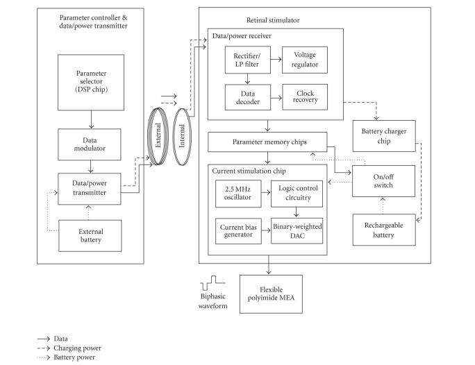
The implantable retinal prosthesis system for a chronic animal experiment consisted of an internal unit for retinal stimulation and an external unit for stimulation control and battery charging (see Figure 1). A paired RF coil links these two units for the transmission of data and power.
Figure 1.
System block diagram.
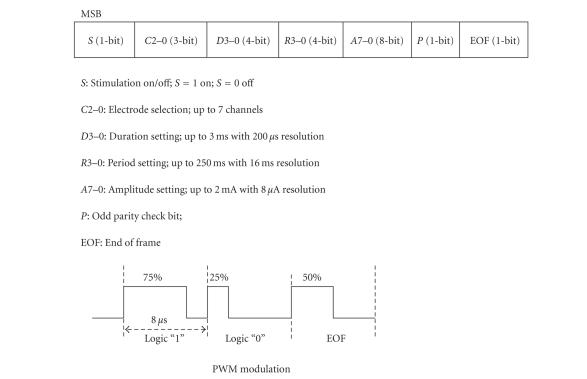
The external unit had a stimulation waveform parameter selector used to control the channel selection, amplitude, duration, and rate of stimulation. This parameter selector generated a parameter data frame and was implemented using a commercially available digital signal processing chip (TMS320VC5509, Texas Instruments, Dallas, Tex, USA). The control codes were implemented in-house using the C programming language, and the parameter data frame consisted of 22 bits as shown in Figure 2. The same stimulation waveform was simultaneously delivered to all selected channels. To transmit this parameter data into the internal stimulator, the pulse width modulation (PWM) encoding method was used (see Figure 2). Logic “1” and “0” were encoded to have a duty cycle of 75% and 25%, respectively, and the “end-of-frame (EOF)” bit had a 50% duty cycle. Such an encoding method enables easier synchronization and decoding because each bit had a uniform rising edge at its beginning [18]. The transmission data rate was 125 kbps. For transmission of PWM encoded data, a class-E tuned power amplifier (data/power transmitter) was used with amplitude shifted keying (ASK) modulation. The carrier frequency was 2.5 MHz.
Figure 2.
Data formats and PWM modulation.
The transmitted data were received by the internal coil and then the envelope was extracted through a half-wave rectifier and a lowpass filter. Using this envelope signal, a data decoder in the data/power receiver chip recovered the parameter data and saved it to the parameter memory chip. Using the same envelope signal, a voltage regulator generated power to be consumed by the data/power receiver chip (see Figure 1).
The internal unit, that is, the retinal stimulator, was implemented with a rechargeable battery and integrated circuit (IC) chips including the data/power receiver chip, current stimulation chip, parameter memory chips, and battery charging chip. The data/power receiver chip had data decoding and voltage regulation function blocks. Both the data/power receiver chip and the current stimulation chip are custom IC's designed by our laboratory (0.8 m complementary metal-oxide semiconductor (CMOS) technology, Austria Microsystems, Unterpremstaetten, Austria). The parameter memory and battery charging chips were off-the-shelf commercial products (see Figure 1). Except for the data/power receiver chip, the other chips in the stimulator were powered by a rechargeable battery. Therefore, once the parameters were passed to the parameter memory, the external unit can be removed from the animal during the electrical stimulation test. The retinal stimulator had two modes of function: a stimulation mode and a battery recharging mode.
In stimulation mode, the saved parameter data in the parameter memory component were provided to the current stimulation chip. The parameter memory component was composed of three 8-bit shift registers (SN54AHC595, Texas Instruments, Dallas, Tex, USA) for 22-bit data storing. The parameter data did not change unless a new parameter was transmitted from the external component. The current stimulation chip consisted of seven current sources and a timing logic circuitry. The current generator circuitry had current bias circuitry (8 μA) and an 8-bit binary current-weighted DAC (digital-to-analog converter). The timing logic circuitry had a 2.5 MHz oscillator and switch control logic circuitry for controlling the current stimulation waveform.
In the battery recharging mode, 2.5 MHz sinusoidal waves were transmitted with no data. A rechargeable coin-type lithium ion battery (PD2320, Korea Power cell Inc., Daejeon, Korea) was used as the power source for the internal implant. A charging chip (LTC4054L, Linear Technology Corporation, Milpitas, Calif, USA) was used to control the battery recharging.
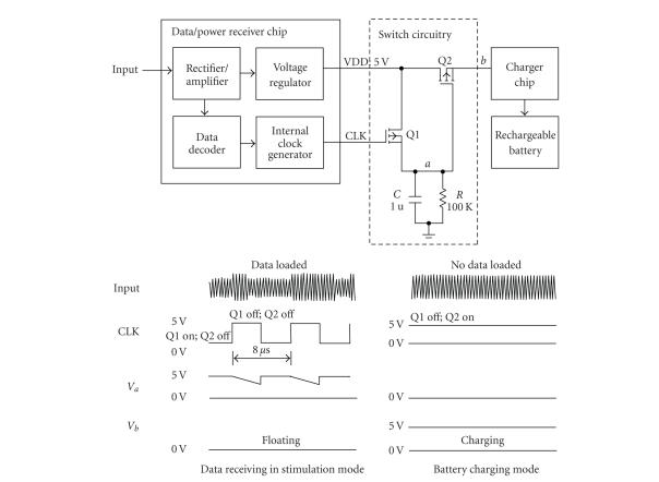
In this work, only one inductive coupling was used for data transmission and battery charging. Simultaneous transmission of the stimulation parameter and charging power is difficult because the battery charger circuit affects the precisely designed load value of the data/power receiving circuit and can induce the failure in data reception. To separate the stimulation mode and battery charging mode, a switch circuit was positioned between the voltage regulator in the data/power receiver chip and the battery charge chip to control the recharging of the battery. The introduced switch circuit consisted of two p-MOS transistors, one capacitor and one resistor (see Figure 3). The resistor and capacitor comprised a parallel connection with an RC time constant of 100 millisecons, which was very long compared to the 8-microsecond period of the clock of the data/power receiver chip. Therefore, the voltage of the “a” node was higher than the threshold of the Q2 switch when a data signal (PWM) was applied causing the Q2 to turn off. The data decoding could therefore be successfully carried out with no load effect. However, when only a sinusoidal wave without data was applied to the retinal stimulator through the inductive link, the level of CLK was logic high (see Figure 3). In this case, Q1 would be turned off and the voltage of node “a” would be logic low, so Q2 would be turned on. Therefore, the battery could be recharged.
Figure 3.
Operation of switch circuitry in stimulation and battery charging modes. When no data were loaded on 2.5 MHz carrier, CLK was logic high, therefore switch Q1 would be turned off, and the voltage of “a” node would be logic low, so switch Q2 would be turned on (battery recharging mode). If any data were loaded on 2.5 MHz carrier, the CLK would recover and the voltage of node “a” never went below the threshold of switch Q2, so Q2 was turned off, this would be disabling the charger chip period (stimulation mode).
To protect the ICs from body fluids and mechanical forces, the electronics of the stimulator were hermetically housed in a metal package which consists of biocompatible titanium housing, platinum feedthroughs, and a ceramic plate. The feedthroughs connected the electrode array and receiver coil to the retinal stimulator. A ceramic sintering process was used to fix the feedthroughs in the ceramic plate that provided electrical isolation. Brazing and laser welding techniques were employed to achieve hermetic sealing of the titanium housing [18].
A polyimide-based seven-channel, strip-shaped (750 300 m) gold electrode array was used as stimulating electrode. The stimulation sites were constructed in a 4 mm 4 mm area with a seven segmented configuration [17]. A large circle electrode in 1500 m diameter, also polyimide-based, was used as the reference electrode (see Figure 4). The thickness of polyimide/gold electrode array was 58 m. One side of this array was lengthened and connected to the stimulator via feedthroughs.
Figure 4.
A photograph of retinal electrical stimulator which consists of receiver coil, hermetically sealed metal package, and polyimide-based active and reference electrodes.
2.2. Surgical procedures for implantation of the prosthesis system into rabbits
New Zealand White rabbits weighing 2.02.5 kg were used to evaluate the proposed system. All procedures of animal experimentation were approved by the Institutional Review Board of Seoul National University Hospital Clinical Research Institute and followed the Association for Research in Vision and Ophthalmology (ARVO) Statement on Use of Animals in Ophthalmic and Vision Research. Implantation of the entire system was performed under general anesthesia achieved by repetitive intramuscular injection of 25 mg ketamine and 6 mg xylazine per kilogram of body weight.
The skin was prepared and a longitudinal incision was made at the right auscultation triangle of the back. Meticulous dissection was done between the subcutaneous and muscular layers. A subcutaneous tunnel was made by an elevator from the medial angle of the scapula to the inferior conjunctival fornix. The forniceal opening was created with a blade and the tip of the elevator was extruded from the forniceal opening thereby completing the subcutaneous tunnel. The internal stimulator was inserted into the subcutaneous tunnel from the opening of the back. The connection part and the polyimide electrode array were protected by a soft polyethylene tube and passed through the tunnel. After being introduced through the conjuctival forniceal opening, the connection wire was turned around the eyeball under the extraocular muscles and temporarily anchored onto the sclera with two 6-0 Prolene sutures, which is a process similar to Humayun's method [4].
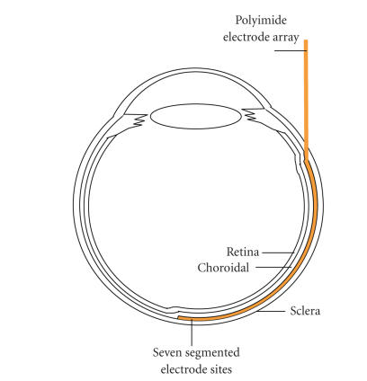
A 5 mm sized Scleral tunnel incision parallel to the limbus was made with a blade and scissors about 5 mm away from the limbus in the upper lateral quadrant of the eyeball. To prevent vitreous prolapse and to lower the intraocular pressure, 0.1–0.2 mL of aqueous humor was drained from the anterior chamber before the scleral opening was created. The polyimide electrode array was inserted through the scleral opening and slided into the suprachoroidal space to reach the visual streak. Figure 5 shows the position of the electrode array in the rabbit eye ball. The scleral opening was closed with 8-0 Vicryl sutures and the connection wire was permanently anchored onto the sclera with sutures. The reference electrode was left outside the eyeball to contact the sclera without fixation. The conjunctival incisions were repaired with 8-0 Vicryl sutures and the skin incision was repaired with 6-0 Catgut sutures. After the operation, the entire system was inside the body and was not exposed.
Figure 5.
A diagram showing the positioning of an electrode array in the rabbit eye ball. The electrode array is colored in yellow. (Figure 9(a) shows a fundus photography of rabbit retina with a suprachoroidal electrode.)
2.3. Recording of visually/electrically evoked cortical potentials
Stainless needle electrodes were used as recording electrodes. An active recording electrode was placed into the primary visual cortex 6 mm lateral and 6 mm anterior to lambda, which is the same location as in Okuno's method [19]. A reference recording electrode was placed into the cortex 20 mm anterior to lambda. The animal was grounded by an electrode on the ipsilateral ear. The visually evoked cortical potentials (VECPs) and electrically evoked cortical potentials (EECPs) elicited by stimulating one eye were recorded from the active recording electrode placed on the contralateral side.
An integrated hardware/software platform (TDT System 3, Tucker-Davis Technologies, Alachua, Fla, USA) was used for amplifying, acquisition, and storage of VECP and EECP signals. This platform could flexibly integrate devices for the intended purpose. In our recording system, there were a four-channel low-impedance headstage (RA4L1), a 16-channel preamplifier (RA16PA Medusa PreAmps), a DSP device (RA16BA Medusa Base Station), and a PC interface module (FI5/PI5-to-zBus). Signals were digitized at 25 kHz on the preamplifier and sent over a fiber optic link to a DSP device where they were filtered (0.5–300 Hz) and processed in real time. Ordinarily, 30 consecutive responses were summed and averaged on one VECP/EECP record.
For recording the VECP, a photopic stimulator (Neuropack 2 plus, Nihon Kohden, Tokyo, Japan) was positioned 3 cm above the rabbit eye. The stimulator intensity setting was 1.2J, and flash frequency was 1 Hz.
For recording the EECP, a cathodic-first biphasic constant current stimulus waveform was simultaneously applied to all selected active channels. Both pulse duration and interpulse delay were 1 millisecond and amplitudes were varied as noted. The repetition frequency was 4 Hz.
During the electrical stimulation, real-time signals also were recorded by a cornea contact electrode through another recording channel in the above recording system. From these recorded signals, the stimulation artifact signals were extracted and used as the trigger signal for EECP recording. In our measurements, the delay of the extracted trigger signal compared to the stimulation signal was less than 500 microseconds and had a constant value.
2.4. Long-term follow-up of rabbit retina and implanted electrodes
We observed the rabbits from 1 month to 16 months. We used OCT (optical coherence tomography, Stratus OCT Model 3000, Carl Zeiss Ophthalmic System, Dublin, Calif, USA) and fundus photography to evaluate the biocompatibility of the polyimide electrodes.
3. RESULTS
3.1. Retinal prosthesis system
A current mode, charge-balanced, cathodic-first biphasic stimulation waveform was generated in the stimulation mode and provided to a stimulation electrode array. The current stimulation chip could simultaneously deliver a stable current from 8 μA to 2 μA to all channels. The pulse width and the interphase delay could be changed up to 3 milliseconds. The interphase delay was designed to have the same time duration as the pulse width.
The fabricated polyimide electrode array was checked for electrode impedance in vitrousing a commercial potentiostat (Zahner Elektrik IM6e, Germany). Impedance for the strip-shaped electrode site (750 μm 300 μm) was typically 1.3 and for the reference electrode was typically 300 Ω in phosphate-buffered solution (pH 7.4) as measured at 1 kHz.
In vivo electrode impedance of the stimulation electrode site was checked for two weeks postsurgery. The potentiostat was connected to the sites through a percutaneous connector. Impedance between a strip-shaped site and the reference electrode was typically near 10 at 1 KHz and there was no significant change during the two-weeks monitoring period. The result is detailed in Table 1.
Table 1.
Measured impedance at 1 KHz in vivo for two weeks after implantation. The strip-shaped seven-segment electrode array was placed into the suprachoroidal space and reference electrode was placed on the surface of sclera. A strip-shaped electrode site was connected to the working electrode input, and the stimulating reference electrode served as the counter and reference electrode. 0 week means the day of implantation.
| Site No. | Impedence (kohm)/Phase (degree) | ||
|---|---|---|---|
| 0 week | 1 week | 2 weeks | |
| 1 | 10.50 (−42.8) | 9.50 (−44.5) | 9.99 (−45.7) |
| 2 | 14.10 (−40.3) | 13.30 (−35.0) | 13.00 (−29.3) |
| 3 | 9.01 (−43.2) | 9.48 (−41.6) | 11.23 (−39.7) |
| 4 | 13.70 (−41.3) | 10.40 (−38.9) | 11.80 (−39.4) |
| 5 | 9.29 (−38.0) | 10.94 (−40.9) | 9.08 (−36.9) |
| 6 | 10.25 (−45.9) | 9.67 (−43.0) | 8.98 (−40.7) |
| 7 | 8.94 (−43.8) | 10.08 (−46.7) | 12.60 (−39.2) |
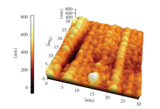
The surface of the gold stimulation site was checked with an atomic force microscopy (AFM) image (AFM, PSIA, XE-150) as shown in Figure 7. The surface average roughness of gold electrode array was 68 nm.
Figure 7.
An AFM image of gold/polyimide electrode surface. The average surface roughness was 68 nm.
The stimulation outputs were connected to 1.3 resistive loads, modeling the electrodes. The stimulator consumed around 2 mW when delivering 520-μA biphasic current pulse with 1-millisecond pulse width at a stimulation rate of 4 Hz.
The capacity of the battery was 75 mAh (4.2 V) and the battery could supply the power to the internal circuitries for over 30 hours under the 520-μA amplitude, 1-millisecond stimulation duration. The battery was fully recharged within three hours with 25 mA charging current through the RF inductive link when in the battery recharging mode.
Table 2 summarizes the implantable stimulator specifications and performance.
Table 2.
Specification summary of the implanted stimulator.
| Hermtically packaged stimulator | 35 mm(L) 26 mm (W) 8 mm (H) |
| Diameter of internal coil | 28 mm |
| Length of lead between electrode and stimulator | 20 cm |
| Stimulator electrode | 4 mm 4 mm |
| Stimulation site of the electrode | 750 um 300 um |
| Electrode site impedance | 1300 ± 106 ohm at PBS solution pH 7.4 |
| Number of current generator | 7 |
| Data packet | 22 bits |
| Stimulation duration (number of bits; minimum duration) | 4-bit (200 us) |
| Stimulation amplitude (number of bits; minimum amplitude) | 8-bit (8 uA) |
| Power consumption (520 uA, 1 ms, 4 Hz) | 2 mw |
| Rechargeable battery size | 20 mm (D) 4 mm (H) |
| Rechargeable battery capacity | 75 mAh (4.2 V) |
| Recharging time | 3 hours (25 mA charging current) |
3.2. Postoperative state of rabbits
Implantation of the stimulation system into the rabbit was successfully achieved. The internal portions were harbored safely and postoperatively remained in situ, as verified with fundus photography. There were no limitations in eye movements or shoulder movements on the implanted side and the entire stimulation system could be safely protected under the skin during the follow-up period. There was no need to anesthetize the rabbit while changing the stimulation parameters by attaching the external RF coil onto the skin overlaying the internal RF coil.
3.3. VECP & EECP
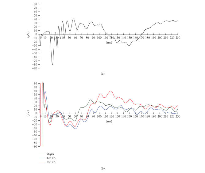
Figure 8 shows a typical VECP and EECP recording for a single rabbit with varying stimulus current. The overall shapes and latencies of VECP waves were similar to previous reports [19]. The EECP were well recorded upon electrical stimulation from the implanted electrodes. The EECP disappeared after the optic nerves were severed.
Figure 8.
(a) Visual-evoked cortical potential (VECP) recorded before implantation of electrodes. (b) Electrically evoked cortical potentials (EECP) following retinal stimulation with a suprachoroidal electrode.
Threshold current necessary to elicit the EECP's were also recorded from another animal for six weeks postsurgery. Seven channels were stimulated simultaneously using a biphasic pulse repeated at 4 Hz with a 1-millisecond duration/phase and a 1-millisecond interphase delay. The threshold ranged from 80 μA to 128 μA during the testing period but did not show any significant change. The detailed measured threshold currents and calculated charge density values are shown in Table 3. The threshold was the highest (128 μA) on the day of implantation but then fell and remained at lower values for the duration of monitoring. The threshold charge density was similar to the value reported in [20].
Table 3.
Threshold current to elicit the EECP. Seven channels were used simultaneously and the duration of the pulse was a biphasic current pulse, 1 ms/phase with a 1-millisecond interphase delay. The repetition rate was 4 Hz. 0 week means the day of implantation.
| Time after implantation | Threshold current (μA) | Threshold charge density per phase (μC/cm2) |
|---|---|---|
| 0 week | 128 | 48.64 |
| 1 week | 104 | 39.52 |
| 2 weeks | 80 | 30.40 |
| 3 weeks | 96 | 36.48 |
| 4 weeks | 80 | 30.40 |
| 5 weeks | 104 | 39.52 |
| 6 weeks | 80 | 30.40 |
3.4. Long-term follow-up results
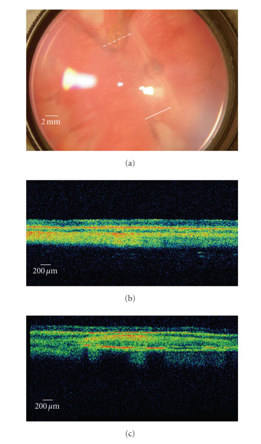
The fundus photography and OCT findings are shown in Figure 9. The Stratus OCT 3000 showed fine resolution of cross-sectional retinal images of rabbits. We can distinguish each layer of retina and choroid by OCT. All the implanted electrodes were detected in the suprachoroidal space, which was in the same location of the retina as immediately after surgery. The eyes with polyimide-based gold electrodes showed no chorioretinal reaction around the electrodes (see Figure 9(a)). The implanted electrodes did not cause any chorioretinal inflammation and structural deformity during 16 months of the follow-up period.
Figure 9.
(a) A digital fundus photography of rabbit retina implanted with a suprachoroidal electrode with two OCT (Stratus OCT 3000) scan paths (solid and dashed lines). A polyimide-based gold electrode had been implanted. Under gross inspection, the electrode is in its original position near the visual streak and no chorioretinal abnormalities can be found. (b) The OCT scan of the retina remote from the electrode (the solid line in the fundus photography). The normal structures of the rabbit retina and choroid is demonstrated. (c) The OCT scan passing the electrode vertically (the dashed line in the fundus photography). The electrode is observed in the suprachoroidal space and in tight contact with the choroid. The metal plates in the electrode are highly reflective and leave posterior shadowing. The overlying retina showed normal structures of layers.
4. DISCUSSION
In retinal prosthesis research, long-term electrical stimulation experiments in animal are needed to verify the long-term stability and durability of the system before clinical use. Retinal prosthesis systems for electrical stimulation usually consist of external and internal units [21, 22]. The external unit is necessary to change the stimulation parameters and to provide power for the implanted stimulator, but it is also burdensome especially in long-term animal electrical stimulation experiments.
The stimulation system presented in this article was intended to provide a useful tool for long-term animal experiments on retinal prostheses. To remove the external connection or the external unit from the animal during electrical stimulation, we used a small rechargeable battery in the implantable stimulator. This battery could be simply recharged using an RF inductive link while the system was idle. This system makes it possible to conduct chronic electrical stimulation tests in such a way that the animal can move and act freely without any external unit restriction during the stimulation test. Therefore, there is no need to anesthetize the animal frequently and the stimulation system is also protected from the animal's claws and teeth.
The implantable retinal stimulator was built using IC chips and discrete elements for this proof-of-concept. An IC chip can be developed to reduce power consumption and further miniaturize the implanted component of the device.
During the implantation of the polyimide electrode array into the eye and the inside of orbit, we adopted Humayun's method [4], making one turn of the electrode along the equator of the eye under the extraocular muscles to provide stability. The elongated polyimide electrode is flexible, thus simple folding of the connection part can provide much degrees of freedom, and this enables eye movement without limitation of motion.
There are pros and cons regarding the ocular location of implantation of the electrodes. To our thought, the suprachoroidal implantation of electrodes has many advantages over the conventional subretinal implantation.
First, as the electrode does not contact retinal cells directly, there is no risk of mechanical retinal damage from direct contact with electrode which could be initiated during surgical procedure. A past report comparing subretinal and suprachoroidal retinal implantation in rabbits also showed histologically proven retinal damage in the subretinal implantation while there was none in the suprachoroial implantation [12]. Second, in the suprachoroidal implantation method, the retina could be protected from heat damage generated from electrodes. As the choroidal blood flow is much larger than in other organs in human body, the large amount of choroidal blood flow will carry away the heat from the electrodes and protect the retina from heat damage [23]. Third, the surgical procedure of suprachoroidal implantation is more simple and safer than subretinal implantation. To introduce electrodes into the suprachoroidal space, it is not necessary to induce retinal tears and retinal detachment. In the case of retinal detachment during subretinal implantation, the electrode could inhibit retinal reattachement after implantation and could cause redetachement.
The suprachoroidal implantation also has weaknesses as compared to subretinal implantation. The threshold of suprachoroidal implantation was shown to be larger than the subretinal electrode [12]. The distance from the electrodes to inner retinal cells might influence the impedence of electric current and this may cause problems in making fine resolution pattern electrodes.
Our suprachoroidal approach was similar to the previous method [20] in many aspects. However, we placed the reference electrode on the outer scleral surface without penetrating vitreous cavity. In our result, the placement of the reference electrode in the extraocular space showed effective stimulation of the retina which was evidenced by EECP and was safer than the previous method [20] without risk of ocular damage from penetrating vitreous cavity.
In the present study, we confirmed the feasibility of our electrodes by observing the propagation of electrically induced signals to the visual cortex by a conventional recording method.
Moreover, the biocompatibility of the electrode was evaluated with OCT and fundus photography. The gold electrode was safe and biocompatible as late as 16 months after introduction. OCT gives in vivo cross-sectional retinal images of 10 μm resolution and is an in vivo biomicroscopy method [24, 25]. OCT was recently used to evaluate the subretinally implanted microphotodiode arrays in cats and pigs [26, 27] and epiretinal electrodes in dogs [8]. To our knowledge, we are the first to evaluate the biocompatibility of suprachoroidal electrodes which were implanted into rabbits. OCT was especially useful in detecting the subtle amount of retinal inflammation when no retinal pathology could be found with fundus photography.
In conclusion, we have demonstrated a new design for a retinal electrical stimulator which can be used safely in the long term. More animal experiments are needed to improve our system and to further develop an advanced system for use in humans.
Figure 6.
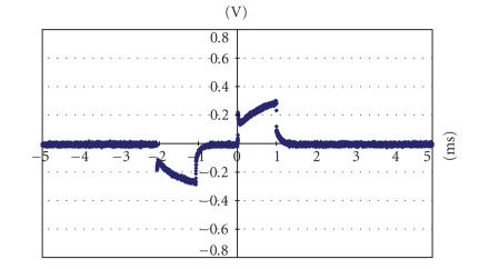
The voltage drop between a strip-shaped electrode (in the suprachoroidal space under visual streak) and the reference electrode (on the surface of sclera) with 104 uA current intensity (upon implantation.)
ACKNOWLEDGMENTS
This work was supported by the Korean Science and Engineering Foundation (KOSEF) through the Nano Bioelectronics and Systems Research Center (NBS-ERC) of Seoul National University under Grant No. R11-2000-075-01001-0 and by the Ministry of Health & Welfare (South Korea) through the Nano Artificial Vision Research Center under Grant of the Korea Health 21 R&D Project (A050251). This material was presented, in part, at The World Congress on Engineering (ICSBB 2007), July 2007.
References
- 1.Wickelgren I. A vision for the blind. Science. 2006;312(5777):1124–1126. doi: 10.1126/science.312.5777.1124. [DOI] [PubMed] [Google Scholar]
- 2.Hessburg PC, Rizzo JF., III The eye and the chip. World congress on artificial vision 2006. Journal of Neural Engineering. 2007;4(1) [PubMed] [Google Scholar]
- 3.Rizzo JF, III, Wyatt J, Loewenstein J, Kelly S, Shire D. Perceptual efficacy of electrical stimulation of human retina with a microelectrode array during short-term surgical trials. Investigative Ophthalmology & Visual Science. 2003;44(12):5362–5369. doi: 10.1167/iovs.02-0817. [DOI] [PubMed] [Google Scholar]
- 4.Humayun MS, Weiland JD, Fujii GY, et al. Visual perception in a blind subject with a chronic microelectronic retinal prosthesis. Vision Research. 2003;43(24):2573–2581. doi: 10.1016/s0042-6989(03)00457-7. [DOI] [PubMed] [Google Scholar]
- 5.Hornig R, Laube T, Walter P, et al. A method and technical equipment for an acute human trial to evaluate retinal implant technology. Journal of Neural Engineering. 2005;2(1):S129–S134. doi: 10.1088/1741-2560/2/1/014. [DOI] [PubMed] [Google Scholar]
- 6.Chow AY, Chow VY, Packo KH, Pollack JS, Peyman GA, Schuchard R. The artificial silicon retina microchip for the treatment of vision loss from reinitis pigmentosa. Archives of Ophthalmology. 2004;122(4):460–469. doi: 10.1001/archopht.122.4.460. [DOI] [PubMed] [Google Scholar]
- 7.Chow AY, Pardue MT, Perlman JI, et al. Subretinal implantation of semiconductor-based photodiodes: durability of novel implant designs. Journal of Rehabilitation Research and Development. 2002;39(3):313–322. [PubMed] [Google Scholar]
- 8.Güven D, Weiland JD, Maghribi M, et al. Implantation of an inactive epiretinal poly(dimethyl siloxane) electrode array in dogs. Experimental Eye Research. 2006;82(1):81–90. doi: 10.1016/j.exer.2005.05.008. [DOI] [PubMed] [Google Scholar]
- 9.Schanze T, Sachs HG, Wiesenack C, Brunner U, Sailer H. Implantation and testing of subretinal film electrodes in domestic pigs. Experimental Eye Research. 2006;82(2):332–340. doi: 10.1016/j.exer.2005.07.007. [DOI] [PubMed] [Google Scholar]
- 10.Seo JM, Kim SJ, Chung H, Kim ET, Yu HG, Yu YS. Biocompatibility of polyimide microelectrode array for retinal stimulation. Materials Science and Engineering C. 2004;24(1-2):185–189. [Google Scholar]
- 11.Walter P, Heimann K. Evoked cortical potentials after electrical stimulation of the inner retina in rabbits. Graefe's Archive for Clinical and Experimental Ophthalmology. 2000;238(4):315–318. doi: 10.1007/s004170050358. [DOI] [PubMed] [Google Scholar]
- 12.Yamauchi Y, Franco LM, Jackson DJ, et al. Comparison of electrically evoked cortical potential thresholds generated with subretinal or suprachoroidal placement of a microelectrode array in the rabbit. Journal of Neural Engineering. 2005;2(1):S48–S56. doi: 10.1088/1741-2560/2/1/007. [DOI] [PubMed] [Google Scholar]
- 13.Margalit E, Weiland JD, Clatterbuck RE, et al. Visual and electrical evoked response recorded from subdural electrodes implanted above the visual cortex in normal dogs under two methods of anesthesia. Journal of Neuroscience Methods. 2003;123(2):129–137. doi: 10.1016/s0165-0270(02)00345-x. [DOI] [PubMed] [Google Scholar]
- 14.Zrenner E, Besch D, Bartz-Schmidt KU, et al. Subretinal chronic multi-electrode arrays implanted in blind patients. Invesigative Ophthalmology & Visual Science. 2006;47:1538. [Google Scholar]
- 15.Humayun MS, Hopkins J, Greenwald SH, et al. Electrical effects and perceptual performance using a chronically implanted 16-channel epiretinal prosthesis in blind subjects. Invesigative Ophthalmology & Visual Science. 2006;47:3212. [Google Scholar]
- 16.Güven D, Weiland JD, Fujii G, et al. Long-term stimulation by active epiretinal implants in normal and RCD1 dogs. Journal of Neural Engineering. 2005;2(1):S65–S73. doi: 10.1088/1741-2560/2/1/009. [DOI] [PubMed] [Google Scholar]
- 17.Zhou JA, Kim ET, Seo JM, Chung H, Kim SJ. A seven segment electrode stimulation system for retinal prosthesis. Invesigative Ophthalmology & Visual Science. 2006;47:3178. [Google Scholar]
- 18.An SK, Park SI, Jun SB, et al. Design for a simplified cochlear implant system. IEEE Transactions on Biomedical Engineering. 2007;54(6):973–982. doi: 10.1109/TBME.2007.895372. [DOI] [PubMed] [Google Scholar]
- 19.Okuno T, Oku H, Ikeda T. The reproducibility and sensitivity of visual evoked potential testing in rabbits. Neuro-Ophthalmology. 2001;26(1):59–66. [Google Scholar]
- 20.Sakaguchi H, Fujikado T, Fang X, et al. Transretinal electrical stimulation with a suprachoroidal multichannel electrode in rabbit eyes. Japanese Journal of Ophthalmology. 2004;48(3):256–261. doi: 10.1007/s10384-004-0055-1. [DOI] [PubMed] [Google Scholar]
- 21.Suaning GJ, Lovell NH. CMOS neurostimulation ASIC with 100 channels, scaleable output, and bidirectional radio-frequency telemetry. IEEE Transactions on Biomedical Engineering. 2001;48(2):248–260. doi: 10.1109/10.909646. [DOI] [PubMed] [Google Scholar]
- 22.Liu W, Sivaprakasam M, Singh PR, Bashirullah R, Wang G. Electronic visual prosthesis. Artificial Organs. 2003;27(11):986–995. doi: 10.1046/j.1525-1594.2003.07306.x. [DOI] [PubMed] [Google Scholar]
- 23.Parver LM, Auker C, Carpenter DO. Choroidal blood flow as a heat dissipating mechanism in the macula. American Journal of Ophthalmology. 1980;89(5):641–646. doi: 10.1016/0002-9394(80)90280-9. [DOI] [PubMed] [Google Scholar]
- 24.Puliafito CA, Hee MR, Lin CP, et al. Imaging of macular diseases with optical coherence tomography. Ophthalmology. 1995;102(2):217–229. doi: 10.1016/s0161-6420(95)31032-9. [DOI] [PubMed] [Google Scholar]
- 25.Fujimoto JG, Huang D, Hee MR, et al. Physical principles of optical coherence tomography. In: Schuman JS, Puliafito CA, Fujimoto JG, editors. Optical Coherence Tomography of Ocular Diseases. 2nd edition. Thorofare, NJ, USA: SLACK; 2004. pp. 677–698. [Google Scholar]
- 26.Völker M, Shinoda K, Sachs HG, et al. In vivo assessment of subretinally implanted microphotodiode arrays in cats by optical coherence tomography and fluorescein angiography. Graefe's Archive for Clinical and Experimental Ophthalmology. 2004;242(9):792–799. doi: 10.1007/s00417-004-0935-6. [DOI] [PubMed] [Google Scholar]
- 27.Gekeler F, Szurman P, Grisanti S, et al. Compound subretinal prostheses with extra-ocular parts designed for human trials: successful long-term implantation in pigs. Graefe's Archive for Clinical and Experimental Ophthalmology. 2007;245(2):230–241. doi: 10.1007/s00417-006-0339-x. [DOI] [PubMed] [Google Scholar]


