

Abstract
Biodegradable synthetic matrices that resemble the size scale, architecture and mechanical properties of the native extracellular matrix can be fabricated through electrospinning. Tubular conduits may also be fabricated with properties appropriate for vascular tissue engineering. Achieving large cell infiltrate within the electrospun matrix in vitro remains time consuming and challenging. This difficulty was overcome by electrospraying smooth muscle cells concurrently with electrospinning of a biodegradable, elastomeric poly(ester urethane)urea (PEUU) small diameter conduit. Constructs were cultured statically or in spinner flasks. Hematoxylin and eosin (H&E) staining demonstrated qualitatively uniform SMC integration radially and circumferentially within the conduit after initial static culture. In comparison with static culture, samples cultured in spinner flasks indicated 2.4 times more viable cells present from MTT and significantly larger numbers of SMCs spread within the electrospun fiber networks by H&E image analysis. Conduits were strong and flexible with mechanical behaviors that mimicked those of native arteries, including static compliance of 1.6 ± 0.5 × 10⁻³ mmHg−1, dynamic compliance of 8.7 ± 1.8 × 10⁻⁴ mmHg−1, burst strengths of 1750 ± 220 mmHg, and suture retention. This method to rapidly and efficiently integrate cells into a strong, compliant biodegradable tubular matrix represents a significant achievement as a tissue engineering approach for blood vessel replacement.
Keywords: Blood Vessel, Electrospray, Electrospinning, Elastomer, Polyurethane, Smooth Muscle Cell
1. Introduction
Given the incidence of coronary and peripheral arterial disease - and the complications associated with treatment - the need for engineered tissue replacements for small diameter blood vessels is clear. Research has been pursued by a wide variety of groups aimed at creating a blood vessel tissue equivalent based upon cells and extracellular matrix alone (cultured into sheets and rolled) [1, 2], cells combined with natural materials (e.g. fibrin and collagen) [3–6], and cells combined with synthetic matrices (e.g. hydrolytically labile polyesters) [7–10]. Common to many of these approaches, particularly those that possess higher cell densities are inadequate vessel mechanical properties. Although a synthetic or processed natural matrix can provide mechanical support, this usually comes at the expense of long culture times which can be on the order of months [1, 2, 9].
A critical requirement of blood vessel replacements is accurate replication of the original vessel compliance. Compliance mismatch is a complex phenomenon involving the mechanical response of blood vessel walls to pulse waves. At the interfaces between native arteries and graft (anastomoses) [11] the flow can be perturbed causing altered-shear stress areas which favor platelet deposition and thrombosis. These complications can further lead to myointimal hyperplasia and consequent graft failure. Therefore, in developing an ideal blood vessel replacement, it is necessary to not only create a non-thrombogenic luminal surface but to also closely replicate the elastic properties of the vessel wall.
Biodegradable elastomers represent ideal scaffolding materials to utilize for replication of native vessel compliance behaviors. In particular, thermoplastic biodegradable polyurethanes offer a high degree of tunability achievable by appropriate selection of hard and soft segments. An elastomeric biodegradable poly(ester urethane)urea (PEUU) developed in our laboratory based on a poly(ε-caprolactone) diol soft segment and a hard segment of 1,4-diisocyanatobutane and putrescine has been shown to be cytocompatible, produce non-toxic degradation products, and be processable into scaffolding by an electrospinning technique [12, 13].
Electrospun PEUU nanofibers are attractive in that they possess extracellular matrix (ECM) similar architecture appropriate to serve as cell scaffolding [13]. Moreover, the electrospun PEUU matrix can be produced with the appropriate tissue mimicking mechanical anisotropy appropriate for tissue scaffolding [14]. To produce a highly cellularized construct, but to also provide substantial elastomeric mechanical support, we were the first to develop an approach wherein a meshwork of submicron elastomeric fibers was built during cellular placement [15]. This process, termed “microintegration,” utilized electrohydrodynamic atomization to simultaneously electrospray cells while electrospinning PEUU nanofibers. This process overcame inherent challenges in obtaining cell infiltration into the small pore sizes of an electrospun scaffold in vitro by literally surrounding cells with the fiber matrix as it was constructed. The resulting scaffold sheets were strong and flexible with large numbers of spread cells infiltrated throughout their bulk after only a few days of perfusion culture [15].
In this work, the microintegration process has been extended to fabrication of small diameter tubular conduits appropriate for blood vessel tissue engineering. Vascular smooth muscle cells were electrosprayed during electrospinning of a small diameter biodegradable and elastomeric PEUU tubular conduit. The objective was to utilize this combined electrohydrodynamic atomization method to produce highly cellularized small diameter conduits after only a few days in culture that possessed mechanical properties similar to native vessels. These constructs were cultured under appropriate static or spinner flask conditions and subsequently characterized for their cellularity and mechanical properties. Viable cell numbers were measured at each timepoint and cell morphologies within construct cross-sections were examined. Mechanical properties of the constructs such as static and dynamic compliance, stiffness index, burst pressure, ultimate tensile stress, stretch to failure, modulus, and suture retention were calculated as appropriate for vascular tissue engineering.
2. Materials and Methods
2.1 Polymer synthesis
Solvents dimethyl sulfoxide (DMSO) and N,N–dimethylformamide (DMF) were dried over 4-A molecular sieves. Polycaprolactone diol (PCL, Aldrich, MW = 2000) was dried under vacuum for 48h at 50°C. Putrescine (Sigma) and 1,4-diisocyanatobutane (Fluka) were distilled under vacuum. Stannous octoate (Sigma) catalyst and hexafluoroisopropanol (HFIP, Oakwood) solvent were used as received. Biodegradable and biocompatible PEUU was synthesized from BDI and PCL with putrescine chain extension as described previously [12]. Synthesis occurred as a solution polymerization with DMSO using a 2:1:1 BDI: PCL: putrescine molar ratio. PEUU cast films were prepared from a 3 wt% solution in DMF and dried under vacuum for 48 h.
2.2 Conduit cell microintegration/electrohydrodynamic atomization technique
Vascular smooth muscle cells (SMCs) isolated from rat aortas were expanded on tissue culture polystyrene (TCPS) culture plates under Dulbecco’s Modified Eagle Medium (DMEM) supplemented with 10% fetal bovine serum and 1% penicillin-streptomycin [16]. Cellular microintegration was performed similar to methods described previously with modifications to allow for fabrication of a small diameter tube as depicted in Fig. 1 [15].
Fig. 1.
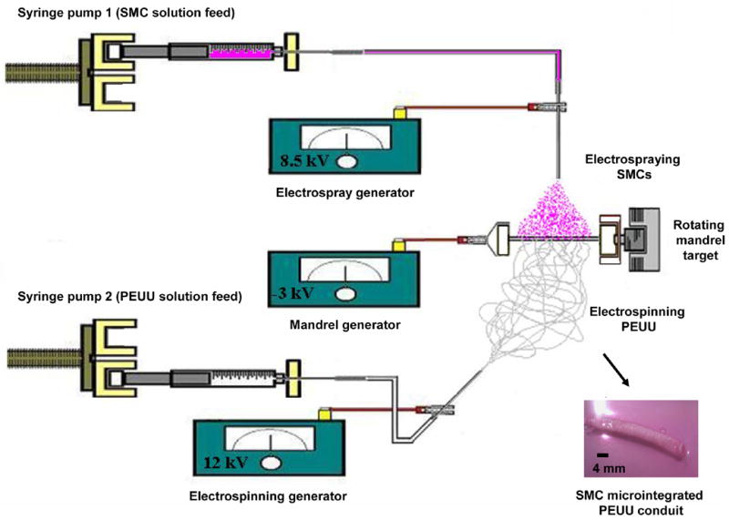
Schematic to illustrate cellular microintegration process as applied for small diameter blood vessel construct fabrication. A perpendicular nozzle configuration is utilized for electrospinning PEUU (6 wt% in HFIP at 1.5 mL/hr) and electrospraying SMCs (7.5 × 10⁶ SMCs/mL in medium at 0.1 mL/min) onto a rotating small diameter mandrel (4.7mm, 250 rpm) transversing on a linear stage (1.6 mm/s). The macroscale appearance of SMC microintegrated PEUU tubular constructs are illustrated after removal from the mandrel (bottom right hand corner).
SMCs (7.5 × 10⁶/mL) were subcultured in medium and fed by syringe pump (Harvard Apparatus PhD) at 0.1 mL/min into a sterile Type 316 stainless steel nozzle (I.D. = 1.2 mm) charged at 8.5 kV and located 4.5 cm above the target. 6 wt% PEUU in HFIP was fed at 1.5 mL/min through sterile tubing into a sterile nozzle (I.D. = 1.2 mm) charged at 12 kV and located 23 cm from the target in a perpendicular configuration with the electrospray nozzle. The target consisted of a sterile stainless steel mandrel (4.7 mm diameter) charged at −3 kV and rotating at 250 rpm while translating 8 cm along its axis at a rate of 1.6 mm/s. Mandrel rotation was achieved using a custom developed electrically insulated motor stand capable of vibration free rotation at high speeds. High voltage was supplied for each component using a combination of three high voltage generators (Gamma High Voltage Research).
A fabrication time of 30 min was used to produce each microintegrated conduit for analysis, one of which is shown in Fig. 1. After fabrication, 8 cm long conduits (n = 4 for SMC and biomechanical characterization, n = 3 for suture retention) on mandrels were covered with fresh media in roller bottles. After 30 min, media was replaced and samples were cultured statically for 1 day. After 1 day, samples were gently pulled from the mandrel and cut into 15 mm tubular section lengths, randomized and either characterized or placed under static culture in tissue culture polystyrene plates or spinner flask culture at 15 rpm for an additional 3 days.
2.3 Characterization of SMC growth and morphology
At timepoints of 1 and 4 days after fabrication constructs were characterized by removing randomly selected 15 mm long tubular sections from static or spinner culture (n = 4 of each sample type) and slicing each in half with one 7.5mm long segment each for MTT and H&E. The MTT mitochondrial activity assay was used to measure cell viability with each sample placed in 200 μL of media supplemented with 20 μL of MTT solution (5 mg of methylthiazolyldiphenyl-tetrazolium bromide per mL PBS, Sigma) into a single well of a 96-multiwell plate immediately after culture. The specimens were kept for 4 h at 37°C. Samples were then immersed in 0.04 N HCl in 2-propanol solution and kept for 48 h at 4°C. The absorbance was read at 570 nm with a 650 nm reference using a microplate reader (Bio-Rad) and normalized to the dry weight of each ring sample. The cell number was obtained utilizing a standard MTT absorbance curve for SMCs of known concentration. Results are displayed as mean ± standard deviation. One-factor analysis of variance (ANOVA) was used to compare means of cell viability with the Neuman-Keuls test for post hoc assessment.
For histological investigation, samples (n = 4, 7.5 mm long segments at each condition) were fixed in 10% neutral buffered formalin at room temperature. Samples were then embedded in paraffin, serially sectioned near construct edge and interior (12 μm thick sections) and stained with hematoxylin and eosin (H&E) using standard procedures. H&E image based analyses were performed with ImageJ software. A manual nuclei count was performed on 20 different squared fields of view (FOV = 0.15 mm2) randomly superimposed at 200x magnification at each experimental condition. In addition, cell density (average cell number per FOV) was compared using ANOVA among the static and spinner culture samples based on the ratio between area occupied by SMCs and the total scaffold area.
2.4 Characterization of conduit biomechanical properties
Biomechanical properties were characterized immediately after samples were removed from spinner flask culture at day 4 after fabrication. Properties measured included static and dynamic compliances, stiffness index, burst pressure, ring uniaxial properties, and suture retention. Static and dynamic compliances and burst pressure were assessed on 15 mm long segments of each construct immersed into a bath of PBS at 37°C within an established vascular testing apparatus (n = 3) [17, 18]. The samples were previously loaded with high viscosity freezing medium (TBS, Triangle Biomedical Sciences) to clog the pores avoiding transluminar flow for a more accurate reading. For static compliance, the constructs were subjected to a pressure ramp (0–200 mmHg) by means of a syringe pump (Harvard Apparatus), and the circuit was clamped downstream while the pump infused PBS at a constant rate (4 mL/min). For dynamic compliance measurements physiologic pulsatile intraluminal pressure (110/70 mmHg) was applied using a Biomedicus centrifugal pump within a closed perfusion loop. For both the static and dynamic compliance measurements the intraluminal pressure was monitored using standard in-line strain-gage pressure transducers (TruWave, Edward Lifesciences,), and outer diameter was measured with a He-Ne laser micrometer (Lasermike). Both signals were recorded at 30 Hz via an acquisition board connected to a personal computer. Compliance, C, was calculated from recordings of pressure, P and a computed inner diameter, Dpin, through the following
| (1) |
[19], where the inner diameter, Dpin, was estimated with the assumption of incompressibility from the cross sectional area, A, of the scaffold and the outer diameter, Dpext, measured via laser micrometer. The parameter, A, was measured using image-based techniques from histological assessment of the same construct. Once A was obtained, it was possible to retrieve the inner diameter at a given pressure from the relative outer diameter measurement by means of
| (2) |
Pressure-diameter relationships during static compliance measurements were also used to compute a dimensional stiffness index, β, via:
| (3) |
Burst pressure was measured by connecting the circuit with a high pressure gauge, clamping the downstream line, and increasing the pressure with a syringe pump infusing at a constant rate of 10 mL/min. The maximum pressure before failure was taken as the burst pressure.
To measure ring strength of the conduits [20], an uniaxial tensile tester (Series 1101, Applied Test Systems) mounted with a 10 lb force transducer (SM-10, Interface) was modified to surround the two clamps with a custom fabricated sealed PBS chamber. A recirculation circuit composed of a roller pump, PVC tubing, and heat exchanger was constructed in order to maintain a constant temperature of 37°C during the tests. A ring of each construct segment was cut (1–2 mm length) and diameter, thickness, and width were measured with a dial caliper. The rings were inserted with two stainless steel flat hooks that were subsequently fixed in the clamps of the testing device and pulled at 10 mm/min crosshead speed until sample failure (n = 4 rings from a 15mm long segment). All specimens were preconditioned prior to testing with 10 cycles at 5% circumferential stretch where stretch, λ, was defined as the sample length normalized to initial length. Load-displacement curves were computed to obtain stress-stretch relationships according to current length and cross-sectional area, A, with the assumption of incompressibility via
| (4) |
A0 was calculated as twice times the initial width and thickness of the ring segment (A0 = 2Wt). Initial sample and test parameters measured on ring segments during the ring test are illustrated in Fig. 2. Ultimate tensile stress and stretch to failure were considered respectively the maximum stress value before failure and its corresponding value of stretch. From the stress-stretch relationship, the respective first derivative curve was computed to demonstrate the instantaneous elastic modulus for each level of stretch. In order to calculate a physiologically relevant elastic modulus, values were taken at a corresponding stretch value to that recorded during inflations under physiological pulsatile conditions in the compliance tests. The maximum elastic modulus and the stretch at maximum elastic modulus were respectively the maximum value of the derivative curve and its corresponding stretch value.
Fig. 2.
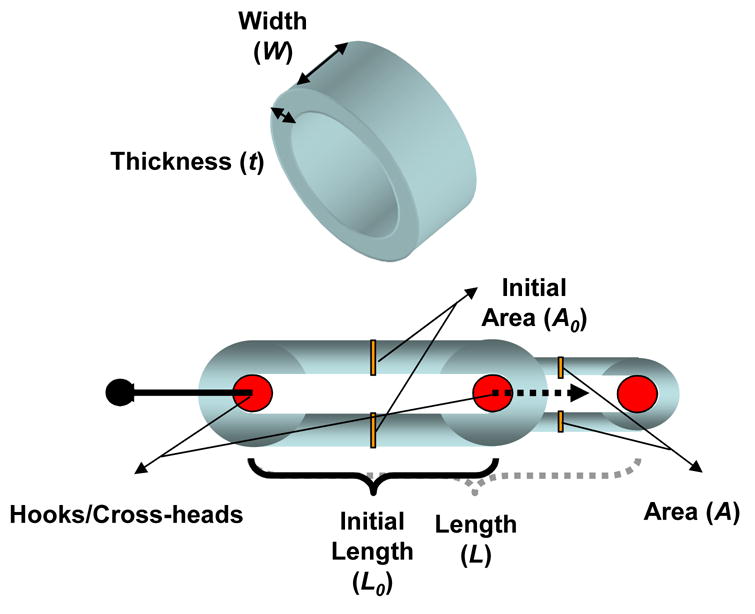
Ring tests were performed to assess stress-stretch tensile properties of microintegrated conduit segments. Sample parameters are illustrated that were used to calculate corresponding stress, stretch and modulus values.
Suture retention was measured at 1 day and 4 days for both static and spinner culture samples in saline at 37°C with the identical testing apparatus as for the uniaxial ring test. Briefly, each tubular construct segment was cut to obtain rectangular specimens (n = 4, length = 15 mm; width = 6 mm) with the short edge of the specimen lying on the circumference of the original segment edge. Wall thickness was measured via a precision dial caliper prior to each test. A single 6-0 prolene loop was created at 5 mm from the short edge of each sample and secured to a hook connected to the upper clamp of the testing device. Suture retention force was considered as the maximum force recorded prior to failure while the suture retention tension was obtained by normalizing the retention force by sample thickness.
3. Results
3.1 Conduit microintegration
In order to extend the technology of cellular microintegration to small diameter tubes, a 4.7 mm diameter stainless steel mandrel was used in the place of the previously employed 19 mm diameter mandrel for sheet microintegration [15]. To manufacture reproducible highly cellular and defect free small diameter tubular constructs, it was necessary to slightly decrease electrospraying distance from 5.0 cm to 4.5 cm and lower the mandrel negative charge from −10 kV to −3 kV from previous methods. During fabrication, conduits appeared pink and glistening on the mandrel indicative of uniform cellular electrospray. After removal from the mandrel, constructs were found to be mechanically robust in that they were suturable and retained their lumens after compression. An image depicting the macroscale appearance of SMC microintegrated PEUU conduits is shown in the bottom right corner of Fig. 1.
3.2 SMC growth and histology
SMC placement and viability in the microintegrated constructs was investigated initially after 1 day of static culture and again after an additional 3 days of static or spinner flask culture. MTT results indicated viable cells 1 day after fabrication with 2.7 ± 1.3 × 10⁴ SMCs/mg construct and at day 4 with 2.2 ± 0.2 × 10⁴ SMCs/mg construct from static culture. Constructs cultured in spinner flasks proliferated to significantly larger cell numbers with 5.4 ± 1.4 × 10⁴ SMCs/mg construct (p < 0.05). MTT viability data are summarized in Fig. 3(a).
Fig. 3.
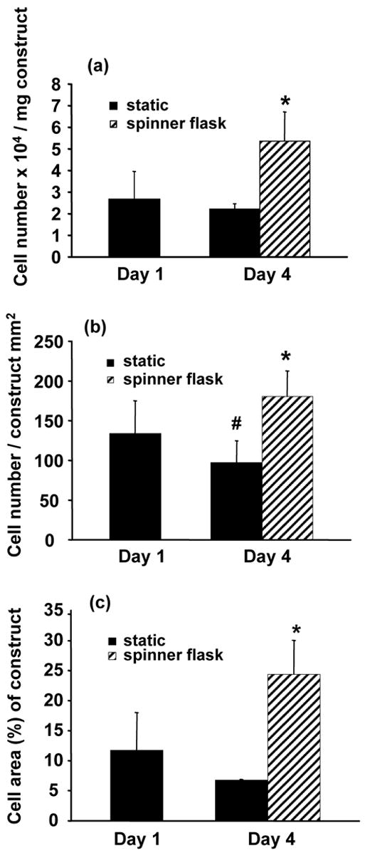
(a) SMC viability by MTT, and quantitative image analysis of H&E sections for (b) number of SMC nuclei and (c) percentage of SMC area relative to scaffold area on microintegrated conduits at 1 day and 4 days after fabrication after static or spinner flask culture at 15 rpm. Spinner flask culture of conduit sections was initiated after 1 day of static culture (*p < 0.05 greater than static 1 day and static 4 day samples, #p < 0.05 less than static 1 day samples).
Representative H&E stained sections were reconstructed to demonstrate radially and circumferentially uniform SMC integration after 1 day of static culture in a half tube section as shown in Fig. 4. These cell morphologies were representative along the spray length (8 cm) of the mandrel. SMC morphologies appeared similar with combinations of smaller rounded cells and some spread cells after either 1 day or 4 days of static culture as exhibited by characteristic images in Fig. 5(a) and Fig. 5(b) respectively. In contrast, significantly numbers of spread cells were evident within constructs at day 4 after spinner flask culture as displayed in Fig. 5(c) and quantified in Fig. 3. Fig. 3(b) and Fig. 3(c) demonstrated significantly higher SMC nuclei and SMC area percent of scaffold area with spinner culture relative to static culture at either timepoint respectively (p < 0.05).
Fig. 4.
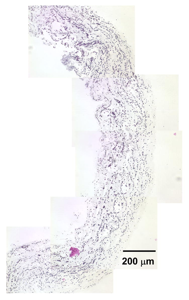
Representative combined images of a half-tube demonstrating radially and circumferentially uniform SMC placement in microintegrated PEUU conduit by H&E staining after 1 day of static culture (scale bar = 200 μm).
Fig. 5.
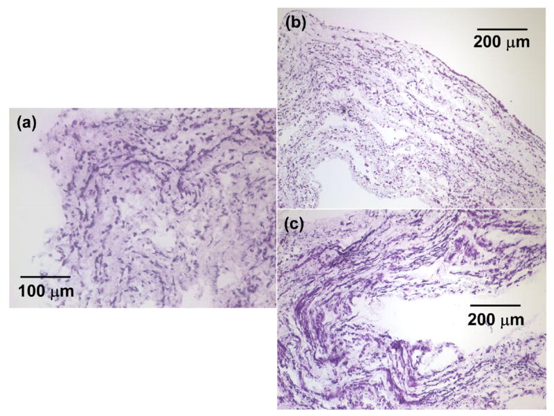
Representative H&E stains of SMC microintegrated PEUU conduits cross-sections after (a) 1 day of static culture (scale bar = 100 μm), (b) 4 days of static culture (scale bar = 200 μm), (c) 1 day of static culture and 3 days of spinner flask culture (scale bar = 200 μm).
3.3 Mechanical properties
Static and dynamic pressure-diameter values were measured on higher cell density SMC microintegrated PEUU tubes immediately after spinner flask culture. The averaged pressure-diameter curves are shown in Fig. 6(a) and Fig. 6(b). From these values, the static and dynamic compliances for SMC microintegrated conduits were found to be 1.6 ± 0.5 × 10⁻³ mmHg−1 and 8.7 ± 1.8 × 10⁻⁴ mmHg−1 respectively. From the dynamic pressure and diameter values in Fig. 6(b), the stiffness index was measured to be 16 ± 3. Constructs were also exposed to increasing pressure until failure to measure burst pressure. Microintegrated constructs were robust with burst pressure values of 1750 ± 220 mmHg.
Fig. 6.
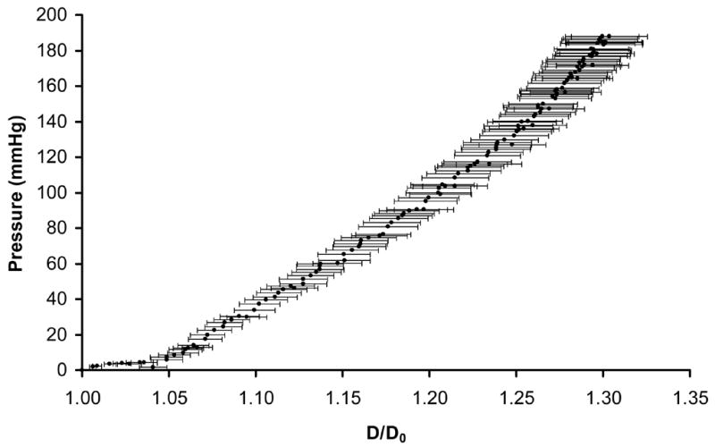

Pressure versus diameter values to depict the (a) static compliance after pressure ramping and (b) dynamic compliance under pulsatile flow of the SMC microintegrated PEUU tubular constructs.
Stress-stretch values were measured by subjecting microintegrated PEUU ring segments immediately after spinner flask culture to tensile testing as illustrated in Fig. 2. The stress-stretch response measured from the tubular sections under aqueous conditions at 37°C is displayed in Fig. 7. The constructs were strong and highly distensible with an ultimate tensile stress of 18 ± 3 MPa and stretch to failure of 3.1 ± 0.3. From the dynamic pressure versus diameter data indicated in Fig. 6(b) a stretch value was taken from D/D0 corresponding to physiological pressures of 110 mmHg and 70 mmHg respectively. This stretch value of 1.03 (corresponding to 3% circumferential stretch) was then used to measure an elastic modulus for the conduit from the first derivative of the stress-stretch curve. This elastic modulus for physiological level of circumferential stretch was 1.0 ± 0.3 MPa. In addition, the maximum elastic modulus was 26 ± 5 MPa and its respective value of stretch was 1.9 ± 0.1. Suture retention demonstrated no significant difference among the three groups but a positive trend was evident of increased retention force and tension for day 4 of spinner culture. Suture retention forces were 1.4 ± 0.2 N, 1.6 ± 0.3 N, 1.9 ± 0.5 N and suture retention tension values were 9400 ± 1600 N/m, 10500 ± 2400 N/m, and 11200 ± 2100 N/m for day 1 static, day 4 static, and day 4 spinner culture correspondingly. Samples possessed an average wall thickness of 163 ± μm. A summary of biomechanical values measured for SMC microintegrated PEUU conduits after day 4 of spinner flask culture is shown in Table 1.
Fig. 7.
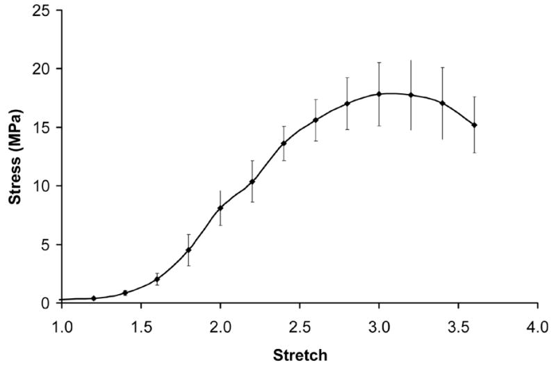
Averaged stress-stretch curve calculated from ring tests of SMC microintegrated PEUU electrospun constructs as illustrated in Fig. 2.
Table 1. Biomechanical properties of SMC microintegrated PEUU small diameter conduits*.
| n | Mean | Standard Deviation | |
|---|---|---|---|
| Static Compliance (mmHg−1) | 3 | 1.6E-03 | 5.3E-04 |
| Dynamic Compliance (mmHg−1) | 3 | 8.7E-04 | 1.8E-04 |
| Stiffness Index | 3 | 16 | 3 |
| Burst Pressure (mmHg) | 3 | 1750 | 220 |
| Ultimate Tensile Stress (MPa) | 4 | 18 | 3 |
| Stretch to Failure | 4 | 3.1 | 0.3 |
| Elastic Modulus (MPa) | 4 | 1.0 | 0.3 |
| Maximum Elastic Modulus (MPa) | 4 | 26 | 5 |
| Stretch at Maximum Elastic Modulus | 4 | 1.9 | 0.1 |
| Suture Retention Force (N) | 4 | 1.8 | 0.5 |
| Suture Retention Tension (N/m) | 4 | 11200 | 2100 |
properties measured after day 4 of spinner flask culture
4. Discussion
Efforts have been extensive in the tissue engineering community to develop a highly cellular and functional blood vessel replacement [1, 2, 5, 21–23]. Central to this theme of functionality was development of grafts that have adequate burst strength and compliance to function in an in vivo environment. Electrospinning technology in particular has been studied for its ability to fabricate small diameter tubular constructs with fiber sizes and architectures that mimic the extracellular matrix [24]. For example, Inoguchi et al. demonstrated the electrospinning of tubular and elastic poly(L-lactide-co-caprolactone) conduits [25]. The mechanical properties of these conduits were investigated and samples were exposed to pulsatile flow in vitro. Work by Vaz et al. demonstrated a multi-layering electrospinning technique to fabricate PCL and PLA composite scaffold conduits and seeded fibroblasts on the material surface [26]. However, to date there have been no reports on a method to simultaneously seed cells by electrohydrodynamic atomization to produce highly cellularized electrospun conduits that possess compliance values similar to native vessels. The objective of this work was to successfully fabricate a highly cellularized blood vessel construct that also provides substantial elastomeric mechanical support.
Previous results in achieving cellular infiltration by conventional seeding and culture methods in electrospun synthetics has been time consuming and difficult. Some believe cells slowly migrate and “push” their way through nanoscale fibers in vitro [27]. Yet, there does not seem to be much incentive for cells to migrate into regions of synthetic materials in vitro that would make diffusion of cell nutrients and waste more difficult. However, it would be expected that when implanted in vivo electrospun scaffolds would be more quickly infiltrated with cells as a result of the highly dynamic environment including potential inflammatory responses. To assess this concept, Telemeco et al. subcutaneously implanted synthetic electrospun materials and compared these with electrospun collagen and gelatin [28]. The most rapid and adequate cellular infiltration was observed for electrospun collagen. Slow infiltration and some fibrous encapsulation occurred on the synthetic PGA and PLA electrospun materials. While this study was only for 1 wk, it did demonstrate that cellular infiltration was relatively slow in vivo as well for electrospun synthetics.
Since the ability to seed cells into electrospun synthetics in vitro is limited by the small pore sizes of the electrospun scaffold, we have previously reported a microintegrated approach wherein cells are electrosprayed into the submicron fiber networks concurrent with the electrospinning process [15]. A novel perpendicular nozzle set-up was utilized to maximize the combination of cells and fibers at the mandrel surface. This method produced highly cellularized elastomeric scaffolds. Cells were viable after fabrication and proliferated under perfusion culture. No adverse effects were observed as an effect of either processing voltage or solvent with one hypothesis being that the positively charged cells and fibers repelled each other and avoided contact until they were at the mandrel surface. Given the relatively large electrospinning distance of 20 cm, electrospun PEUU would likely be devoid of highly volatile processing solvent at the mandrel surface.
In order to effectively microintegrate cells into small diameter tubular constructs some process variables were modified from the previous approach. For example, to adequately target cells onto the smaller diameter mandrel it was necessary to decrease the electrospray distance between the nozzle and mandrel compared with the distance used for the larger diameter mandrel previously [15]. Also, applying a high negative charge to the rotating 4.7 mm mandrel target resulted in polymer protrusion defects, “spikes,” in the construct which could disrupt conduit integrity and cell viability. Therefore, we decreased the negative mandrel charge magnitude to result in more reproducible and homogenous cell infiltrate and fibrous tubular conduits.
These constructs were then placed under static culture for a short time period to allow for cell attachment and prevent cell washout that could occur under dynamic conditions. After static culture randomized samples were placed in spinner flask culture to encourage better exchange of nutrients, waste, and oxygen to the cells in the conduit interior. MTT results and H&E staining indicated viable cells present throughout the constructs after fabrication and static or spinner flask culture. With static conditions, SMCs appeared more rounded and less spread. This effect may have been due to poor exhange of nutrients, waste, and oxygen in the construct interior or increased cell and fiber alignment in the axial direction of the tubes. However, processing conditions were such that mandrel translation speed was kept low (1.6 mm/s) relative to rotation (250 rpm) to influence better fiber and cell orientation around the circumference and not axial direction. A similar SMC morphology was not observed from spinner flask culture. In particular, spinner flasks led to significantly improved cell number and increased spread cell morphologies within the constructs as expected. While it must be noted that MTT can in some cases not directly correlate with cell number given potential variances in mitochondrial activity with different culture media and conditions [29], H&E image analysis corroborated significant trends in cell number observed by the MTT data. Also, while the SMC microintegration results observed were very promising in terms of the large cell densities cultured within the constructs, further analysis is warranted to better understand the effects of the fabrication process on SMC function and phenotype.
Given the larger cell numbers observed in the constructs after spinner culture, these samples were examined for their biomechanical properties as they would be expected to be most relevant for vascular tissue engineering. The biomechanical properties of these SMC microintegrated tubes were assessed and found to be strong and flexible with compliances, stiffness, and burst strengths appropriate for blood vessel replacement. Values can be compared with those of Tajaddini et al. who recently provided a thorough mechanical characterization of human coronary arteries, [30] which represent the main targets for future clinical applications of small-diameter engineered vessels. According to those published data the microintegrated tubular constructs appear to have very similar mechanical properties to those of healthy coronary arteries (compliance = 14.1 ± 5.9 × 10⁻⁴ mmHg, stiffness index = 16.9 ± 7.1, elastic modulus = 1.41 ± 0.72 MPa). In addition, the burst pressures of the microintegrated conduit were similar to those reported for the human saphenous vein (1680 ± 307 mmHg) which is a current preferred replacement graft [1]. Suture retention force of the microintegrated conduit were similar to those reported for either the human coronary artery (1.96 ± 1.1 N) or saphenous vein (1.92 ± 0.02 N) [2]. The relatively slow in vitro degradation rate for these materials previously reported also would lead one to expect a gradual decrease in mechanical properties over time [12, 13]. Also, given the strength and flexibility observed in the ring test, the constructs should be resistant to catastrophic failure in vivo due to any large perturbation in mechanical loading. However, it is important to note that in vivo phenomena such as inflammation and fibrosis might alter the mechanical properties of the constructs with time in a manner unpredicted by in vitro studies. For culture under cyclic mechanical training in vitro, the elastomeric properties of these conduits appear to be appropriate for a mechanically demanding environment.
The conduits fabricated in this study were highly cellularized with SMCs throughout their interior. However, in order to serve as a blood vessel replacement the conduit would most likely also require a non-thrombogenic luminal surface. Such a surface could be achieved in vitro by either luminal seeding or sequential microintegration of appropriate endothelial cells. Fast and repeatable luminal seeding of electrospun PEUU small diameter tubes has already been demonstrated using a custom designed rotating vacuum device [31]. This method could easily be used for microintegrated electrospun PEUU as well. Another method to seed endothelial cells in the material lumen would be to sequentially microintegrate first endothelial cells and then smooth muscle cells into the electrospun PEUU with a PEUU thin lamina to separate the layers. This sequentially cell integrated construct could also be subsequently luminal seeded using the reported vacuum device.
5. Conclusions
Cellular microintegration offers a means to simultaneously seed cells and fabricate nanofibrous tubular scaffolding. More specifically, SMCs were electrosprayed concurrent with PEUU electrospinning to produce a hybrid tissue engineered blood vessel construct that was highly cellular and reinforced with an elastomeric fiber matrix. These conduits were demonstrated to be cytocompatible, strong, and possess compliance values similar to native vessels. These methods represent a significant advance over conventional electrospinning technologies and provide a means to electroprocess cells in a viable manner.
Acknowledgments
This work was supported by the Commonwealth of Pennsylvania and the National Institutes of Health, (#HL069368). We sincerely acknowledge Drs. Jianjun Guan, Alejandro Nieponice, and Michael Sacks for their support and guidance on this project. In addition, we thank Dan McKeel for his assistance in refining the rotating target used during fabrication.
Footnotes
Publisher's Disclaimer: This is a PDF file of an unedited manuscript that has been accepted for publication. As a service to our customers we are providing this early version of the manuscript. The manuscript will undergo copyediting, typesetting, and review of the resulting proof before it is published in its final citable form. Please note that during the production process errors may be discovered which could affect the content, and all legal disclaimers that apply to the journal pertain.
References
- 1.L’Heureux N, Paquet S, Labbe R, Germain L, Auger FA. A completely biological tissue-engineered human blood vessel. Faseb J. 1998;12:47–56. doi: 10.1096/fasebj.12.1.47. [DOI] [PubMed] [Google Scholar]
- 2.L’Heureux N, Dusserre N, Konig G, Victor B, Keire P, Wight TN, et al. Human tissue-engineered blood vessels for adult arterial revascularization. Nature Med. 2006;12(3):361–5. doi: 10.1038/nm1364. [DOI] [PMC free article] [PubMed] [Google Scholar]
- 3.Weinberg CB, Bell EB. A blood vessel model constructed from collagen and cultured vascular cells. Science. 1986;231:397–400. doi: 10.1126/science.2934816. [DOI] [PubMed] [Google Scholar]
- 4.L’Heureux N. In vitro construction of a human blood vessel from cultured vascular cells: a morphologic study. J Vasc Surg. 1993;17:499–509. doi: 10.1067/mva.1993.38251. [DOI] [PubMed] [Google Scholar]
- 5.Ratcliffe A. Tissue engineering of vascular grafts. Matrix Biol. 2000;19:353–7. doi: 10.1016/s0945-053x(00)00080-9. [DOI] [PubMed] [Google Scholar]
- 6.Cummings CL, Gawlitta D, Nerem RM, Stegemann JP. Properties of engineered vascular constructs made from collagen, fibrin, and collagen-fibrin mixtures. Biomaterials. 2004;25:3699–706. doi: 10.1016/j.biomaterials.2003.10.073. [DOI] [PubMed] [Google Scholar]
- 7.Badylak SF, Lantz G, Coffey A, Geddes LA. Small intestinal submucosa as a large diameter vascular graft in the dog. J Surg Res. 1989;47:74–80. doi: 10.1016/0022-4804(89)90050-4. [DOI] [PubMed] [Google Scholar]
- 8.Hoerstrup SP, Zund G, Sodian R, Schnell AM, Grunenfelder J, Turina MI. Tissue engineering of small caliber vascular grafts. Eur J Card Thor Surg. 2001;20:164–9. doi: 10.1016/s1010-7940(01)00706-0. [DOI] [PubMed] [Google Scholar]
- 9.Niklason LE, Gao J, Abbott WM, Hirschi KK, Houser S, Marini R, et al. Functional arteries grown in vitro. Science. 1999;284(5413):489–93. doi: 10.1126/science.284.5413.489. [DOI] [PubMed] [Google Scholar]
- 10.Yue X, Schakenraad JM, van Oene GH, Kuit JH, Feijen J. Smooth muscle cell seeding in biodegradable grafts in rats: a new method to enhance the process of arterial wall regeneration. Surgery. 1988;103:206–12. [PubMed] [Google Scholar]
- 11.Greisler H, Zilla P. Tissue Engineering of Vascular Prosthetic Grafts. Austin; Landes: 1999. [Google Scholar]
- 12.Guan J, Sacks MM, Beckman EJ, Wagner WR. Synthesis, characterization, and cytocompatibility of elastomeric, biodegradable poly(ester-urethane)ureas based on poly(caprolactone) and putrescine. J Biomed Mater Res. 2002;61:493–503. doi: 10.1002/jbm.10204. [DOI] [PubMed] [Google Scholar]
- 13.Stankus J, Guan J, Wagner WR. Fabrication of biodegradable elastomeric scaffolds with sub-micron morphologies. J Biomed Mater Res. 2004;70A:603–14. doi: 10.1002/jbm.a.30122. [DOI] [PMC free article] [PubMed] [Google Scholar]
- 14.Courtney T, Sacks MS, Stankus J, Guan J, Wagner WR. Analysis and design of tissue engineered scaffolds that mimic soft tissue mechanical anisotropy. Biomaterials. 2006;27:3631–8. doi: 10.1016/j.biomaterials.2006.02.024. [DOI] [PubMed] [Google Scholar]
- 15.Stankus JJ, Guan J, Fujimoto K, Wagner WR. Microintegrating smooth muscle cells into a biodegradable, elastomeric fiber matrix. Biomaterials. 2006;27:735–44. doi: 10.1016/j.biomaterials.2005.06.020. [DOI] [PMC free article] [PubMed] [Google Scholar]
- 16.Ray JL, Leach R, Herbert JM, Benson M. Isolation of vascular smooth muscle cells from a single murine aorta. Methods Cell Sci. 2002;23:185–8. doi: 10.1023/a:1016357510143. [DOI] [PubMed] [Google Scholar]
- 17.Raghavan ML, Webster MW, Vorp DA. Ex vivo biomechanical behavior of abdominal aortic aneurysm: assessment using a new mathematical model. Annals of Biomedical Engineering. 1996;24(5):573–82. doi: 10.1007/BF02684226. [DOI] [PubMed] [Google Scholar]
- 18.Severyn D, Muluk S, Vorp D. Effects of arterial hemodynamics and cyclic strain on platelet deposition to human saphenous vein segments perfused ex-vivo. Adv Bioeng. 1996;33:479–80. [Google Scholar]
- 19.Pham SJDS, Johnson R, Endean ED, Vorp DA, Borovetz H, Greisler HP. Compliance changes in bioresorbable vascular prostheses after implantation. Surg Forum. 1988;29:330–2. [Google Scholar]
- 20.Hayashi K, Takamizawa K, Saito T, Kira K, Hiramatsu K, Kondo K. Elastic properties and strength of a novel small-diameter, compliant polyurethane vascular graft. J Biomed Mater Res. 1989;23:229–44. [PubMed] [Google Scholar]
- 21.Greisler H. Biointeractive polymers and tissue engineered blood vessels. Biomaterials. 1996;17:329–36. doi: 10.1016/0142-9612(96)85571-2. [DOI] [PubMed] [Google Scholar]
- 22.Hamilton D, Vorp D. Encyclopedia of Biomaterials and Biomedical Engineering. New York: Marcel Dekker; 2004. Tissue engineering of blood vessel. [Google Scholar]
- 23.Isenberg BC, Williams C, Tranquillo RT. Small-Diameter Artificial Arteries Engineered in Vitro. Circ Res. 2006;98:25–35. doi: 10.1161/01.RES.0000196867.12470.84. [DOI] [PubMed] [Google Scholar]
- 24.Annis D, Bornat A, Edwards RO, Higham A, Loveday B, Wilson JT. An elastomeric vascular prosthesis. Am Soc Art Int Org. 1978;24:209–14. [PubMed] [Google Scholar]
- 25.Inoguchi H, Kwon IK, Inouse E, Takamizawa K, Maehara Y, Matsuda T. Mechanical responses of a compliant electrospun poly(L-lactide-co-caprolactone) small-diameter vascular graft. Biomaterials. 2006;27:1470–8. doi: 10.1016/j.biomaterials.2005.08.029. [DOI] [PubMed] [Google Scholar]
- 26.Vaz CM, Van Tuijl S, Bouten CVC, Baaijens FPT. Design of scaffolds for blood vessel tissue engineering using a multi-layering electrospinning technique. Acta Biomat. 2005;1:575–82. doi: 10.1016/j.actbio.2005.06.006. [DOI] [PubMed] [Google Scholar]
- 27.Li WJ, Laurencin CT, Caterson EJ, Tuan RS, Ko FK. Electrospun nanofibrous structure: a novel scaffold for tissue engineering. J Biomed Mater Res. 2002;60:613–21. doi: 10.1002/jbm.10167. [DOI] [PubMed] [Google Scholar]
- 28.Telemeco TA, Ayres C, Bowlin GL, Wnek GE, Boland ED, Cohen N, et al. Regulation of cellular infiltration into tissue engineering scaffolds composed of submicron diameter fibrils produced by electrospinning. Acta Biomat. 2005;1:377–85. doi: 10.1016/j.actbio.2005.04.006. [DOI] [PubMed] [Google Scholar]
- 29.Ng KW, Leong DTW, Hutmacher DW. The Challenge to measure cell proliferation in two and three dimensions. Tiss Eng. 2005;11(12):182–91. doi: 10.1089/ten.2005.11.182. [DOI] [PubMed] [Google Scholar]
- 30.Tajaddini A, Kilpatrick DL, Schoenhagen P, Tuzcu EM, Lieber M, Vince DG. Impact of age and hyperglycemia on the mechanical behavior of intact human coronary arteries: an ex vivo intravascular ultrasound study. Am J Physiol Heart Circ Physiol. 2005 Jan;288(1):H250–5. doi: 10.1152/ajpheart.00646.2004. [DOI] [PubMed] [Google Scholar]
- 31.Soletti L, Nieponice A, Guan J, Stankus JJ, Wagner WR, Vorp D. A seeding device for tissue engineered tubular structures. Biomaterials. 2006;27:4863–70. doi: 10.1016/j.biomaterials.2006.04.042. [DOI] [PubMed] [Google Scholar]