Abstract
The study of interactions between carbon nanotubes and cellular components, such as membranes and biomolecules, is fundamental for the rational design of nanodevices interfacing with biological systems. In this work, we use molecular dynamics simulations to study the electrophoretic transport of RNA through carbon nanotubes embedded in membranes. Decorated and naked carbon nanotubes are inserted into a dodecane membrane and a dimyristoylphosphatidylcholine lipid bilayer, and the system is subjected to electrostatic potential differences. The transport properties of this artificial pore are determined by the structural modifications of the membrane in the vicinity of the nanotube openings and they are quantified by the nonuniform electrostatic potential maps at the entrance and inside the nanotube. The pore is used to transport electrophoretically a short RNA segment and we find that the speed of translocation exhibits an exponential dependence on the applied potential differences. The RNA is transported while undergoing a repeated stacking and unstacking process, affected by steric interactions with the membrane headgroups and by hydrophobic interaction with the walls of the nanotube. The RNA is structurally reorganized inside the nanotube, with its backbone solvated by water molecules near the axis of the tube and its bases aligned with the nanotube walls. Upon exiting the pore, the RNA interacts with the membrane headgroups and remains attached to the dodecane membrane while it is expelled into the solvent in the case of the lipid bilayer. The results of the simulations detail processes of molecular transport into cellular compartments through manufactured nanopores and they are discussed in the context of applications in biotechnology and nanomedicine.
INTRODUCTION
Recent advances at the interface of nanotechnology and molecular biology present us with new opportunities for the development of devices such as nanoscale biosensors, molecular motors, and nanosyringes for application domains ranging from bioengineering to nanomedicine (1,2). Biological cells rely on nanoscale components such as ion channels and pumps that regulate key transport processes across cell membranes (3,4). Molecular transport across membranes may also be inflicted by actions of external agents such as viruses binding and puncturing the cell membrane to transfect it with their nucleic acids (5).
The critical role of transmembrane channels and pores in cell biology has prompted several efforts to develop synthetic structures (1,6), with characteristics such as ion and membrane selectivity, voltage and ligand gating, and blockage. Several techniques have been developed for the synthesis of artificial channels based on unimolecular macromolecules, micellar pores, and barrel-stave and barrel-hoop supramolecules (6). The requirements for these channels include structural stability, appropriate trans-membrane orientation, and regulated channel activity (1). These requirements are not always easy to achieve by self-organizing structures; at the same time, the activity regulation of these channels remains an ambitious goal. Alternatively, we may consider the implantation of artificial channels and pores in cell membranes by processes such as conjugation of biological molecules and synthetic polymers as well as by and in situ forming implants (7).
The requirements for structural reliability and low reactivity are met by silica and carbon nanotubes, which are envisioned as prototypes of artificial transmembrane channels and nanosyringes for targeted drug delivery (2). Transmembrane transport in natural ion channels, however, is largely controlled by the structure of membrane proteins whose structure and precise molecular actions may not be easily reproducible with today's nanofabrication techniques. Simpler structures, such as silica-based nanopores (8), can be manufactured, which may provide us with enhanced capabilities for molecular sequencing and selective molecular transport. This possibility has been thoroughly investigated in a series of recent articles (9–13) that reported on the electrophoretically driven transport of DNA in nanometer-size silica pores. In Fyta et al. (14), the molecular dynamics (MD) simulations have been coupled with Lattice-Boltzmann models to study DNA translocation through a pore for extended timescales. The interface between biological systems and artificial nanopores was recently assessed by means of coarse-grained simulations (15–17). These simulations demonstrated that a generic, hydrophobic nanotube functionalized with hydrophilic ends can be spontaneously inserted into a lipid bilayer. In this work, we consider a specific carbon nanotube and we analyze the detailed molecular interactions of the membrane components with the nanotube using molecular dynamics.
Carbon nanotubes are consistent with the requirements for a model nanopore (17), as they are hydrophobic and can be decorated for insertion in membranes. Their low reactivity (18,19) suggests their use as nanometer-size syringes for drug and DNA gene delivery (20) and storage (21). In addition, CNTs can withstand a broad range of voltages and they have been suggested as artificial membranes for DNA sequencing and as stabilizing pores in biological membranes during electroporation. Several recent studies have assessed the interaction of small CNTs with water (22–26), ions (27,28), and nucleic acids (29–31). The regulated channel activity by nanotubes remains a challenge, however, because it requires the integration of suitable gating molecules during their manufacturing. At the same time, the relatively simple structure of the nanotubes, reminiscent of pores consisting of unimolecular macromolecules, can help us to assess the role of complex gating structures in biological channels.
In this study, we use MD simulations to characterize the behavior of decorated and naked CNTs embedded in membranes and assess the role of the CNT decoration for its stabilization in the membrane. We analyze the electrophoretic transport of RNA through these CNTs and quantify interactions of the membrane constituents with the carbon nanotubes. We find that the interplay between the lipid heads and the opening of the nanotube characterizes the electrostatic potential of the CNT, particularly during the electrophoretic transport of biomolecules. The article is structured as follows: In Methods, we describe the setup of the molecular dynamics simulations and present a novel method for inserting and stabilizing CNTs in membranes. In The Electrostatic Potential, we discuss the electrostatics of the CNT embedded in the dodecane membrane and the lipid bilayer, followed by RNA Translocation in Transmembrane CNTs with results from the simulations of the electrophoretic transport of RNA across a membrane-mimetic and a lipid bilayer. In the final section, we conclude with a summary of our findings and their implications for applications at the interface of biology and nanotechnology.
METHODS
Molecular dynamics
Molecular dynamics is a key methodology for the evaluation of new technologies and biological systems at the nanoscale (32). In this study, we employed the MD package FASTTUBE (33), developed in our group for the simulation of carbon nanotubes in aqueous environments, and we visualized the results using VMD (34). The electrostatic interactions were computed using the smooth particle-mesh Ewald method (35). A 32 × 32 × 48 grid was used and validation studies using a 48 × 48 × 64 grid did not show any significant differences in quantities such as the electrostatic potential maps and the structure and speed of translocation of the RNA. The van der Waals interactions and the real-space contribution to the Coulomb interaction were calculated using a cutoff of 1 nm. All systems were kept at a temperature of 323 K by applying a Berendsen thermostat and equilibrated to atmospheric conditions using a Berendsen barostat with a characteristic timestep of 0.1 ps (36).
These MD simulations rely on potentials from the AMBER 96 force field (37) with the extensions proposed in Smondyrev and Berkowitz (38) for modeling phospholipids. Dodecane was modeled using a united atom approach similar to the modeling of lipid tails in Smondyrev and Berkowitz (38). All membrane simulations were carried out at constant area and temperature. A time step of 2 fs was used and all bonds involving hydrogen were kept rigid throughout the simulations. Water was modeled using the TIP3P water model (39). The carbon nanotubes were modeled using the Lennard-Jones parameters for aromatic sp2-carbon of the AMBER 96 force field (37). The bond, angle, and dihedral interaction potentials for the CNT were modeled following Walther et al. (40). In the case of decorated CNTs, the hydroxyl and hydrogen termini are modeled according to corresponding groups in tyrosine in the AMBER 96 force field (37). The charges of the hydroxyl and hydrogen termini were locally balanced on the carbon atoms where the terminal groups are attached to the CNT (0.159 e for the hydroxyl groups and −0.166 for the hydrogen termini).
We note that, even though charged molecules are being transported through the nanotube, we did not model polarizability effects. In an earlier work (25), we have found that the inclusion of dipole terms in the potentials of the nanotubes can alter drastically the transport of water molecules. These effects were found to be significant near the entrance of short nanotubes, leading to L-defects in the water chains, but they were negligible for nanotubes with a diameter wider than 2.5 nm. Several works have considered the polarizability of carbon nanotubes interacting with water (41) and peptides (42). In Lu et al. (41), the polarizability of CNTs has been empirically modeled using atomic partial charges, derived from DFT calculations and a tight-binding model to describe the dielectric response of the CNT. This model was applied to the transport of a nonpolarizable water molecule demonstrating that polarizability influences the water molecules and polar solutes as they are transported by CNTs. In Tomasio and Walsh (42), a polarizable force field has been developed for the interactions of CNTs and peptides and it has been validated by DFT calculations and experiments. The inclusion of polarizability effects was shown to be important for describing the stacking interactions between the aromatic peptide side groups and the CNT. In that work, however, the effects of water were modeled by using an effective continuum solvent. At the moment, there is no force field that has been shown to adequately represent the interaction of the membrane molecules used in this study with the carbon nanotube and the RNA. In addition, as we consider the molecular description of water, nanotubes, RNA, and membranes, the inclusion of polarizability effects in this study would have amounted to prohibitively costly simulations. The absence of polarizability in our modeling is further discussed in RNA Translocation in Transmembrane CNTs, when we present the results of the simulations.
System setup
The dodecane membrane mimetic was set up in a 6.1 nm × 6.1 nm × 10 nm computational box. A slab of 192 dodecane molecules in random orientation with a height of 2.5 nm were placed between two slabs of 3610 water molecules, each ∼3.1 nm thick. After energy minimization, this system was equilibrated by a Berendsen thermostat and a Berendsen barostat acting only in the direction orthogonal to the membrane for 180 ps (36) each, with characteristic times of 0.1 ps. Using the Berendsen barostat, after equilibration, the system was relaxed at constant temperature for another 20 ps. The final extent of the computational domain was 6.1 nm × 6.1 nm × 8.214 nm. The coordinates for the dimyristoylphosphatidylcholine (DMPC) lipid bilayer were obtained from the Tieleman group (PDB file dmpc_npat.pdb from http://moose.bio.ucalgary.ca/index.php?page=Downloads). These coordinates are the result of a 1-ns-long simulation of 128 DMPC molecules solvated in 3655 water molecules.
The carbon nanotubes are based on a (14,14) armchair-CNT with a length of 2.35 nm and a 1.87-nm carbon-to-carbon diameter corresponding to a pore size of ∼1.5 nm (29). We considered two variations of this CNT: The “naked” CNT (with unfilled valences at the ends) and a decorated/doped CNT, where alternating hydroxyl and hydrogen termini were added at its edges (H/OH CNT). The CNT diameter is comparable with the constriction region of the α-hemolysin channel (9,29,43,) and the CNT length is selected so that it minimizes the hydrophobic mismatch with the DMPC membrane (44,45). Due to the limited size of the computational domain, the membrane could not compensate for the effects of a hydrophobic mismatch, which led to destabilization of the lipid bilayer structure.
In these simulations, we considered the transport of single-stranded RNA consisting of 20 adenosine nucleotides. The RNA is hydroxylated at both ends and the charge of the whole system is neutralized by randomly adding potassium counterions to the solvent.
Membrane-CNT setup and equilibration
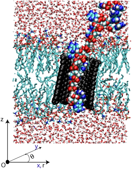
We present a snapshot (Fig. 1) from the simulations of the insertion of the RNA into the CNT to define the geometry of the configuration. Using a cylindrical coordinate system (r, θ, z), the nanotube axis is nominally aligned along the z axis while the membrane surface is largely parallel to the (r, θ) plane.
FIGURE 1.
Illustration of the system after the insertion of RNA (colored spheres) into the CNT (black spheres). The CNT is embedded in a DMPC lipid bilayer. The whole system is solvated in a 1 M potassium chloride aqueous solution. In a cylindrical coordinate system (r, θ, z) the membrane is largely parallel to the (r, θ)-plane while the axis of the nanotube is nominally parallel to the z-axis.
Embedding the CNT in a membrane
The embedding of a CNT in a membrane is hindered by the irregular, unsteady distribution of the lipids. To address this difficulty, Faraldo-Gomez et al. (46) presented a two-stage method, first generating a cavity in a lipid bilayer and then using steered molecular dynamics to insert in it a protein structure.
We introduce a novel technique for the insertion of CNTs into preequilibrated membranes. As a first step, the solvent around the membrane is removed and the bilayer structure is adjusted to accommodate the CNT. In the case of the DMPC bilayer, 14 lipid molecules were removed from the central area of the bilayer corresponding to the nominal volume that would be occupied by a (14,14) CNT. No molecules were removed from the dodecane membrane. Subsequently, a scaling technique was used to insert the CNT: the CNT was initially contracted to a single line of carbon atoms, threaded into the cavity opened in the DPMC bilayer or into the unaltered dodecane membrane. The length-scale parameters σ of all the Lennard-Jones interactions of the CNT molecules were initially set to zero and then linearly scaled to their original value during a period of 2 ps. In the next 28 ps, the radius of the CNT was grown back to its original size. During this process, the positions of the CNT atoms were adjusted so that they correspond to a linear scaling of the CNT radius. Furthermore, the motion of the membrane atoms was restricted to the two in-plane dimensions and the respective velocity components of the membrane atoms were capped at a maximal value of 0.3 nm ps−1. The system was equilibrated for 1 ns and subsequently samples were taken every 1 ps during the course of 1 ns.
We note that this approach differs from the insertion technique presented in Faraldo-Gómez et al.(46) in that it does not require any surface triangulation and it relies on quantities that are computed routinely in MD simulations.
Solvation
After the insertion of CNT into the membrane, the system is solvated by two slabs of ∼1 molar potassium chloride solution. In both cases, 150 potassium and 150 chlorine ions were added to 8127 (for the dodecane membrane) and 8211 (for the DMPC bilayer) water molecules.
For the DMPC bilayer, during the first 40 ps of solvation all phosphorous atoms are kept fixed and the water is relaxed to wet the membrane. This is followed by 4 ps of dynamics where the phosphorous atoms are restricted to move only within the plane of the membrane. After further relaxation and a total simulation time of 60 ps, the system is relaxed using a Berendsen barostat during 200 ps. This is followed by a further relaxation at constant volume for 40 ps.
In the case of the dodecane membrane, its molecules were kept fixed during the first 40 ps of simulation and the water was relaxed to wet the membrane. Subsequently, the velocity of the dodecane molecules was capped at 0.3 nm ps−1 for 4 ps. After a total simulation time of 80 ps, the system was coupled to a Berendsen barostat for 120 ps. The system was further equilibrated at constant volume for another 100 ps to obtain a total of 300 ps for solvation, relaxation, and equilibration.
Insertion of RNA into CNTs
The simulations of RNA transport through the CNT were initialized by placing the RNA in the solvent so that the first phosphorous atom from the 3′-terminus is situated 0.8 nm outside the CNT and on the tube axis. The whole RNA was initially restrained for 46 ps and subsequently only the first phosphorous atom from the 3′-terminus was restrained, while the rest of the RNA was allowed to move freely. Both, the RNA and the membrane were solvated simultaneously.
After solvation and relaxation, the RNA was steered into the CNT (47). A harmonic guiding potential with a force constant of 30,000 kJ nm−2 mol−1 was applied to the first phosphorous atom from the 3′-terminus. The RNA was threaded into the CNT by moving the reference point of the steering potential along the CNT axis during 280 ps. After the steering, the phosphorous atom was restrained at the opening of the CNT to allow for relaxation of structural strain imposed during the steering.
THE ELECTROSTATIC POTENTIAL
The electrostatic potential maps are used to characterize the transport in transmembrane pores (48). We study naked and H/OH-decorated carbon nanotubes, embedded in a dodecane membrane and a lipid bilayer and subjected to an electrostatic potential difference. The random distribution of dodecane molecules and the ordered structure of the lipid molecules are reflected on the electrostatic potential of the system. In the interior of the membrane, the lipid tails of the DMPC have a composition similar to that of the molecules in the dodecane membrane, but their lipid headgroups carry partial charges. The headgroups interact with the decorated rims of the CNT and alter the electrostatic potential in the vicinity of the membrane and near the openings of the transmembrane pore, as detailed later.
The electrostatic potential is assessed following the approach of Aksimentiev et al. (9). We evaluate the electrostatic potential using the method of SPME (33,35). The instantaneous electrostatic potential is radially averaged over 1 ns and presented as an axisymmetric electrostatic potential map. In the related figures, the electrostatic potential map is complemented with the contour lines of the number density for characteristic atoms of the respective setup. These density profiles serve to illustrate the location and mobility of the membrane and the carbon nanotubes.
Electrostatics of a CNT in a membrane
We first present the electrostatic characteristics of a CNT embedded in a membrane without the application of an external potential. The distribution of the electrostatic potential helps us to assess the characteristics of the CNT as a transmembrane channel.
CNT in a dodecane membrane
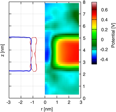
The electrostatic potential map of an H/OH-CNT in an ∼2.5 nm thick dodecane membrane is presented in Fig. 2 along with radially averaged density profiles of their constituent atoms. The hydroxyl and hydrogen termini stabilize the CNT in its transmembrane position and the hydrophilic interaction between the water solution and the termini prevents the dodecane molecules from creeping around the tube rim. The CNT interior forms a channel of low electrostatic potential across the membrane. The electrostatic potential map exhibits distinct zones of high and low potential that are highly correlated with the location of the membrane and the CNT. We measure a potential difference of 0.65 V between the bulk of the ionic solution and the interior of the dodecane membrane, in close agreement with the potential difference found between bulk water and the interior of a lipid bilayer (38).
FIGURE 2.
Radially averaged electrostatic potential map (right) and density profile (left) on the (r, z) plane for a CNT in a dodecane membrane and in the absence of an imposed transmembrane potential difference. The radially averaged density profile indicates the dodecane molecules (blue) and the CNT (red).
CNT in DMPC bilayer
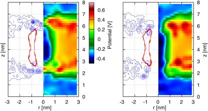
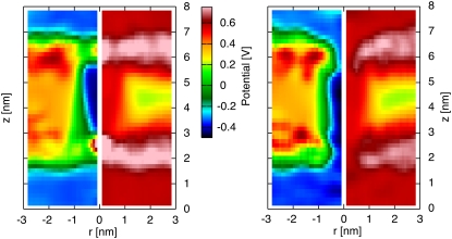
The electrostatic potential maps for the decorated H/OH-CNT and for the naked CNT in a DMPC lipid bilayer are shown in Fig. 3. The H/OH-CNT exhibits a channel of low electrostatic potential connecting both sides of the membrane. On both ends of the membrane, zones of high electrostatic potential protrude into the nanotube and constrict the effective channel opening by 50%, to ∼1 nm in diameter. For the naked CNT these effects are more pronounced, and we observe zones of high electrostatic potential extending across the whole channel and forming barriers (Fig. 3).
FIGURE 3.
Potential maps and density profiles on the (r, z)-plane for a naked CNT (left panel) and a decorated H/OH CNT (right panel) acting as nanopores in a DMPC lipid bilayer in the absence of an imposed electrostatic transmembrane potential difference. The electrostatic potential map (right half in each figure), and density profile (left half in each figure) are plotted to demonstrate correlations between the distribution of the lipid heads and the resulting potential. The density profiles indicate the CNT-carbon atoms (red) and the DMPC-nitrogen atoms (blue). There is no electrostatic potential difference acting across the membrane. Zones of high electrostatic potential protrude slightly into the pore area for the decorated CNT (left), whereas for the case of a naked CNT (right) they form a barrier across the entrance of the tube.
The CNT-DMPC electrostatic potential maps are significantly different from the ones reported for the CNT in the dodecane membrane. The differences are attributed to the DMPC lipid heads that extend further into the solution to access water molecules to satisfy their hydrophilicity. The lipid molecules are arranged into an hourglass shape around the CNT, widening above the area of constriction, while the lipid headgroups are fanning out over the tube rims partially covering the pore openings. This effect is well illustrated by the radially averaged density profiles shown in Fig. 3.
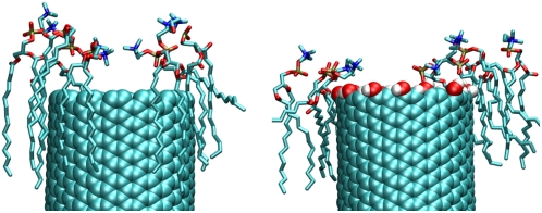
The differences between the naked and the H/OH-CNT are attributed to the solvation of the ester groups of the lipids. The ester groups are stabilized by forming hydrogen bonds with the hydrogen and the hydroxyl groups at the decorated tube rim (Fig. 4). In the case of the naked CNT, this interaction is lacking and the lipids slide along the CNT and toward the water phase, so that the ester groups come into contact with the water at the tube rim (Fig. 4). This configuration is energetically more favorable, allowing for solvation of the carbonyl groups, while at the same time the lipid headgroups extend further over the tube rim, allowing the ammonium groups to leap into the area of the tube opening (Figs. 3 and 4).
FIGURE 4.
Sample snapshot of the lipids at the rims of a naked CNT (left) and a decorated H/OH-CNT (right). The membrane lipids in the vicinity of the naked CNT leap farther into solution and into the tube area. For the H/OH-CNT the hydroxyl groups form hydrogen bonds with the lipids, thus satisfying their solvation requirements and preventing them from fanning over the entrance of the CNT.
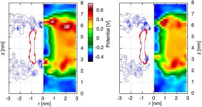
The fanning of the lipid heads into the tube opening is reflected in the distribution of the standard deviation of the electrostatic potential (Fig. 5) having large values in the zone occupied by the lipid headgroups. The charge separation of the choline group promotes significant fluctuations (of ∼5 ns−1) of the electrostatic potential, which are more pronounced for the naked CNT than for the H/OH-CNT. These oscillations are attributed to the strongly correlated reorientation of the lipid headgroups (Fig. 6).
FIGURE 5.
Potential maps on the (r, z)-plane for a naked CNT (left panel) and decorated H/OH CNT (right panel), acting as nanopores in a DMPC lipid bilayer. Standard deviation (right half of each figure) and averaged mean value (left half of each figure) of the electrostatic potential maps on the (r, z) plane. The standard deviation is largest in the area occupied by the lipid heads, indicating their enhanced fanning in the presence of the CNT and lowest in the center of the lipid bilayer.
FIGURE 6.
Two snapshots of the radially averaged electrostatic potential map (right half of each snapshot) and density profiles (left half of each snapshot) of the ammonium group of the dodecane (blue) and the CNT (red) molecules, on the (r, z) plane. The results indicate that the averaged electrostatic potential in the tube opening correlates with the density of the headgroups. As the density is shifted from the center of the tube toward the tube rims, the strength of the electrostatic potential in the tube center diminishes, while the electrostatic potential protruding into the tube area retracts.
We note that the hydrophilicity of membrane heads and the corresponding CNT rim decorations are critical in determining the access to the nanotube entrance. This finding hints at possible regulation and gating mechanisms that may be accomplished by specifying the molecules for the CNT rims so as to control their interactions with the corresponding lipid heads.
Application of a transmembrane voltage difference
A transmembrane voltage difference (8,9,48) is applied to drive a single-stranded RNA segment of 20 adenosine nucleotides through the CNT pore embedded in the membrane.
We first demonstrate that the electrostatic voltage differences induce an asymmetry on the lipid head arrangement on the entrance and on the end-side of the CNT, and affect the overall electrostatic potential maps. We then discuss the electrophoretic transport of the RNA through the CNT and identify a stacking process that depends on steric interactions with lipid heads at the tube entrance and hydrophobic interactions with the walls of the nanotube.
CNT in a dodecane and a DMPC membrane
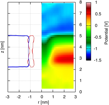
An electrostatic potential of 0.95 V is applied across the system of the H/OH-CNT embedded in the dodecane membrane. The electrostatic potential (Fig. 7) is largely uniform on either side of the membrane, although it changes sharply within the transmembrane nanopore. The potential maps are qualitatively similar to the corresponding maps of solid-state nanopores presented by Heng et al. (10).
FIGURE 7.
CNT in a dodecane membrane. Averaged electrostatic potential map (right), and the corresponding radially averaged density profile for the dodecane (blue) and the CNT (red) molecules on the (r, z) plane. A potential difference of 0.955 V acts across the dodecane membrane.
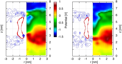
In the case of the DMPC membrane, an electrostatic potential difference of 1.05 V is applied, resulting in the electrostatic potential maps shown in Fig. 8 for both naked and H/OH CNTs. We observe a constant electrostatic potential for the H/OH-CNT on both sides of the membrane accompanied by a high barrier on the side of high electrostatic potential just outside the opening of the CNT (Fig. 8). On the side of low electrostatic potential, a similar barrier is absent for the H/OH-CNT, leading to an opening reflected in a bay of low electrostatic potential extending into the pore. This distribution is due to the absence of lipid headgroups in the area of that tube opening, which is also confirmed by the radially averaged density profiles (Fig. 8).
FIGURE 8.
A naked CNT (left panel) and a decorated CNT (right panel) in a DMPC membrane subject to a electrostatic potential difference of 1.05 V. Radially averaged electrostatic potential map (right half of each figure) and density profile (left side of each figure) on the (r, z) plane of the nitrogen of the DMPC (blue) and the CNT (red) molecules.
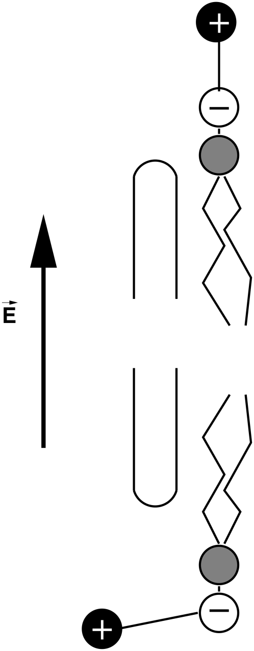
A high barrier on the side of the high potential is also observed in the case of the naked CNT. In contrast, however, with the H/OH-CNT, this barrier is inside the CNT opening. The asymmetry of the electrostatic potential map of the H/OH-CNT is attributed to a reorientation of the membrane, subject to the electrostatic potential differences in the vicinity of the tube entrance. The positively charged ammonium groups of the lipids (38) on the side of high electrostatic potential are pushed by ∼0.7 nm into the area of the H/OH-CNT opening (compare Fig. 9). For the naked CNT, we observe a similar effect with an ammonium density peak just outside the tube opening that is pushed ∼0.7 nm into the tube (Figs. 3 and 8) On the membrane side with low electrostatic potential, the ammonium groups are subject to electrostatic forces which, in turn, pull them away from their equilibrium position, leading to their upright position close to the tube entrance (Fig. 9).
FIGURE 9.
Schematic indicating the reorientation of the headgroups of the lipids close to the carbon nanotube, due to the application of the transmembrane electric field. On the side where the electric field points away from the membrane, the ammonium group of the phospholipid (black) is pushed toward the membrane and thus also over the carbon nanotube rim (indicated by an arc). On the other side, the headgroups of the lipids are stretched and the ammonium group is pulled away from the membrane. The phosphate group is indicated by a white sphere.
In the case of the H/OH-CNT, the lipid headgroups are hardly leaping into the tube area even in the absence of an electrostatic potential difference (Fig. 4). As a consequence, the electrostatic potential difference has a negligible effect on their density distribution on the side of low electrostatic potential (Figs. 3 and 8). Contrastingly, for the naked CNT in the absence of an electrostatic potential difference, the lipid headgroups are leaping into the area of the tube opening (3). As the electrostatic potential difference is applied, the ammonium density retracts by ∼0.5 nm away from the tube axis. The electrostatic barrier reported in the absence of an electrostatic potential difference across the membrane is weaker but still persists in the presence of a potential difference.
We note that the electrostatic potential maps persist for potential differences between 0.2 V and 1.5 V and they are significantly different from the maps obtained for a CNT in a dodecane membrane (Fig. 7) and for solid-state nanopores (11). The lipid headgroups reorient when they are subjected to an electrostatic potential difference leading to different barriers of electrostatic potential for H/OH and naked CNTs. These differences are an essential feature of the steric interactions between an artificial nanopore and a lipid bilayer, and they need to be taken into consideration when designing the insertion of synthetic nanopores (2) in biological membranes. The sensitivity of the lipid head arrangement in naked and decorated CNTS can provide guidance for the design of suitable unsteady voltage differences across the CNT that may regulate access to its entrance. The interplay of nanotube-based pores and the lipid heads is further exemplified in the following section presenting the translocation of RNA through a CNT.
RNA TRANSLOCATION IN TRANSMEMBRANE CNTS
The translocation of ions, DNA, and RNA through biological and synthetic pores has been investigated recently by large-scale MD simulations (10,11,27,32,49) to provide guidance for the design of innovative sequencing devices. In this article, we present MD simulations of RNA transport through a CNT embedded in a dodecane membrane and a DMPC bilayer to study the interplay of the lipid bilayers and the CNT in the translocation of RNA molecules. These simulations provide insight for applications ranging from drug delivery (50) to molecular machines (1,51), where artificial pores are implanted in lipid bilayers.
RNA across a dodecane membrane
A single-stranded piece of RNA consisting of 20 adenosine nucleotides is transported through a naked and H/OH-CNT embedded in a dodecane membrane. The transport is driven by transmembrane potential differences of 1.50–2.10 V in steps of 0.1 V. The potential differences employed in this study are significantly lower than potential differences employed for DNA translocation across synthetic pores (27,49) as the bilayer membrane is ruptured for potential differences of 2.4 V and beyond.
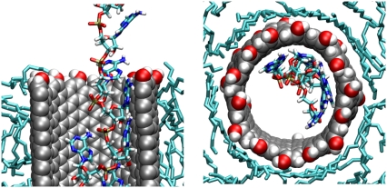
During the translocation, the entrance and exit of the RNA bases in the nanotube is affected by steric interactions of the CNT with the heads of the lipid bilayers, with the RNA bases folding backward with regard to the direction of translocation (52). The transport inside the pore is characterized by hydrophobic interactions between the nucleotide bases (29,30) and the walls of the carbon nanotube (Fig. 10).
FIGURE 10.
Cross section (left) and top view (right) of a single-stranded RNA translocating inside a H/OH-CNT embedded in a dodecane membrane. In the top view, only the RNA fragments within the tube are shown. The nucleotide bases are aligned flat with the tube walls and are folded backward, with respect to the direction of transport. The RNA backbone is exposed toward the center of the tube.
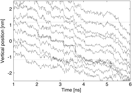
Inside the tube, the RNA bases maximize contact with the CNT, sliding across the pore with their plane largely parallel to the tube walls (Fig. 11). Single and stacked pairs of nucleotide bases are observed, unstacking at the entrance of the CNT, while small groups of RNA bases are observed to restack at their exit from the CNT. During the translocation, the RNA backbone is exposed toward the tube center (Fig. 12), solvating the phosphate and sugar groups of the backbone by the water inside the CNT. This arrangement of the RNA is persistent throughout the simulations and suggests the possibility of using functionalized nanotubes to identify and interact with the RNA bases.
FIGURE 11.
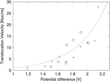
Translocation speed in nucleotides per nano second plotted versus the potential difference across the membrane. Both translocations in an H/OH-CNT (+) and a naked CNT (○) are plotted. An exponential is fitted to the data.
FIGURE 12.
The trajectories of the RNA phosphate groups within the CNT. The two ends of the CNT are indicated by dashed lines. A bold dashed line indicates a steplike motion between 2 ns and 3.5 ns. Afterwards, the RNA gets trapped for a relatively long time span from ∼4 ns until 5.2 ns.
We quantify the translocation of the RNA by relating the speed of translocation with the potential differences applied across the membrane. The speed of translocation is defined by the time between the exit of nucleotide 3 from the tube and the exit of nucleotide 16. This definition was chosen to exclude contributions by end-effects such as nucleotides being expelled from the tube entrance and reduced hydrophobic interactions at the end of the simulation when the RNA is not extended across the whole CNT. For potential differences of 1.20 V and beyond, the RNA was driven through the CNT in relatively short time spans of ∼10 ns. For potential differences between 1.20 and 2.15 V we observe a correlation with the speed of translocation measured in nucleotides per nanosecond (Fig. 11). The measurements were fitted with an exponential function, common in kinetic theories and in drift-diffusion models of molecular translocations in pores (29). The parameters of this exponential were determined by a least-squares fit resulting in an empirical relation between the activation voltage difference (ΔV) and the translocation speed (v),  The speed of translocation exhibits large fluctuations (Fig. 12) and a staircase pattern for potential differences <1.55 V with the longest stop of translocation lasting for ∼1.2 ns. These events are attributed to repeated conformational changes of the RNA during its transport through the CNT. The RNA bases form stacks as they approach the entrance of the CNT, as their hydrophobic interactions intensify. This layering of the RNA chain is broken when a base enters the CNT and the interfacial area is hydrated. In turn, a secondary hydrophobic interaction takes place between the base and the walls of the CNT. The base approaches the CNT wall and aligns itself parallel to it while, at the same time, water molecules are being expelled from that region. The RNA bases are folding backward with regard to the direction of transport, leading to short temporal trappings. This is manifested in the steplike behavior of the trajectories as the RNA bases overcome the energy barrier and unstack.
The strength of the electrostatic potential difference controls the stacking and unstacking of the bases, and the switch between their hydrophobic interaction outside the entrance of the CNT and their hydrophobic alignment with the walls inside the CNT. At electrostatic potential differences of 0.955 V, the RNA gets trapped after 1 ns, as the first two nucleotides are expelled from the tube. In the next eight nanoseconds, no noticeable motion was observed, although the RNA inside the CNT exhibits spatial fluctuations of ∼0.2 nm along the tube axis. The RNA outside the entrance of the CNT moves similarly to free RNA in solution, until, after another seven nanoseconds, one of the terminal attaches to the membrane and remains attached to the membrane throughout the rest of the simulation.
We note that, even at higher electrostatic potential, the RNA bases do not leave the CNT spontaneously, but are eventually pushed away by the remaining RNA bases sliding down within the CNT. One of the first nucleotides, however, usually reattaches quickly to the outside of the tube or the dodecane membrane. The RNA leaving the tube, buckles and forms a loop, which eventually turns into a coiled-up structure. The expelled RNA remains coiled-up at the tube exit during these limited simulation times of 5–10 ns. The RNA was not detached completely from the CNT in any of the simulations conducted in this study that had one or two of the terminal bases always hydrophobically attached to the CNT. (This is similar to the results reported in (8) for synthetic pores.)
For larger potential differences, we observe similar trappings and attachments of the RNA with intermittent periods of fast translocation with speeds of four nucleotides per nanosecond for an electrostatic difference of 1.2 V. For potential differences larger that 1.55 V, we observe trapping of the RNA, but we did not observe any events where individual nucleotides leaving a stacked geometry and entering the tube could be identified by a steplike trajectory as found for smaller potential differences (Fig. 12). The strong driving forces at large potential differences mask the signature of the sequential breaking of the stacking.
RNA across a DMPC bilayer
Simulations of RNA transport are performed for a tube embedded in a DMPC bilayer, to study the effects induced by the structure of the lipid bilayer membrane. The same single-stranded piece of RNA consisting of 20 adenosine nucleotides is transported through a naked CNT and an H/OH-CNT embedded in a DMPC bilayer, which was subject to a potential difference of 1.6 V.
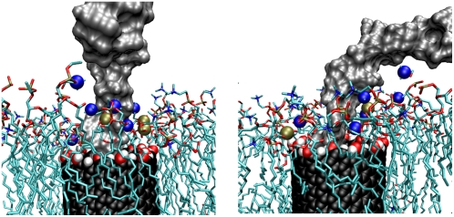
The lipid headgroups of the DMPC membrane extend over the CNT and interact with the RNA (Fig. 13), slowing down its translocation in the tube. In addition, the motion of the RNA is sterically hindered as the lipid heads obstruct the pore opening, similar to the effect described by de Groot et al. (53) and comparable to the entropic barriers reported in Lim et al. (54).
FIGURE 13.
Snapshot of lipid headgroups interacting with RNA (gray) in a transmembrane H/OH-CNT (black/red/white). The lipids are indicated with a colored stick model, and the phosphorous (gold) and nitrogen (blue) atoms within 7 Å of the RNA are indicated with spheres. Both figures show the same snapshot at an angle of 90°.
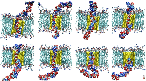
The RNA structure within the CNT in the DMPC lipid bilayer does not significantly differ from the structure in the case of the dodecane membrane. The RNA bases are folded backward with regard to the direction of transport, and they are hydrophobically attracted to the walls of the CNT exposing the bases toward the center of the tube. The translocation (Fig. 14) of the RNA through the tube takes ∼12 ns with an average speed of translocation of 1.5 nucleotides/ns. This speed is significantly lower than the one observed in the case of the dodecane membrane, for similar voltage differences. This effect is attributed to the increased steric interactions of the lipid heads with the RNA. And contrary to the case of dodecane membrane, the RNA does not reattach to CNT as the lipid molecules shield the exterior of the CNT. The RNA leaves the exit area and protrudes into solution while after ∼10 ns the foremost nucleotides get into contact with the lipid bilayer. The RNA, however, is not adsorbed on the lipid bilayer surface but readily diffuses back into solution.
FIGURE 14.
Translocation of RNA through an H/OH-CNT in a DMPC lipid bilayer. The snapshots are taken every 1.4 nanoseconds from 1.4 ns until 11.2 ns.
It is important to recall here that polarizability effects have not been accounted for in these simulations, largely due to their computational expense. We estimate, however, based on previous findings (41,42), that the inclusion of polarizability effects in this configuration would have increased the affinity of the RNA with the walls of the CNT, thus further enhancing hydrophobic effects and further delaying the transport of the RNA through the CNT. The study of polarizability effects in the electrophoretic translocation of RNA in pores and channels, and the embedding of the MD simulations in a multiscale framework where solvation effects are accounted for by these mean-field theories, is a subject of our current investigations.
SUMMARY AND CONCLUSIONS
We use MD simulations to study the electrophoretic transport of a short, single-stranded RNA segment through naked and decorated carbon nanotubes embedded in lipid bilayer and dodecane membranes. These simulations rely on a novel method to insert nanotubes in bilayers. The results enable observations with molecular detail for the interactions of the nanotube with the membrane components. Simulations with dodecane membranes and DMPC lipid bilayers demonstrated that lipid heads, and their coordination with the molecules at the rim of the nanotube, determine to a large extent the transport properties of the nanotube. These properties are further quantified by presenting electrostatic potential maps in the vicinity of the nanotube with and without electrostatic potential differences. We note in particular that the lipid heads of the DMPC bilayer extend above the CNT rims to be solvated by water, thus blocking the entrance of the nanotube and forming an electrostatic potential barrier. This effect may help explain the structure of biological transmembrane pores that exited into the solution.
The transport properties of the CNTs were further quantified by measuring the speed of translocation of a short, single-stranded RNA segment. During the electrophoretic transport of RNA, the lipid heads in the DMPC membrane were found to interact sterically with the transported RNA bases and reduce by half its speed of translocation when compared to the case where the CNT is embedded in a dodecane membrane. In addition, the RNA was found to stay attached to the dodecane membrane, after its exit from the CNT, similar to a behavior that has been observed for other artificial pores. In contrast, it appears that the DMPC lipid heads help the RNA to overcome an entropic barrier so that it enters the solvent after its exit from the CNT. We note, however, that even at strong transmembrane potential differences a few of the terminal nucleotide bases remain hydrophobically attached to the CNT. Chemical modifications to the CNT interior and the tube rims that weaken the hydrophobic interaction of RNA bases and the CNT could promote the detachment of the RNA from the CNT. Possible applications may, however, benefit from the fact that RNA does not detach from the CNT, since the sustained attachment may allow the retraction of the RNA after exposing it to the cell interior. The transport of RNA across a carbon nanotube transmembrane pore compares well with results reported on synthetic silica nanopores (10) and the effects of constriction are similar to results on α-hemolysin (11). While transport velocities in transmembrane CNTs seem to exceed those of an α-hemolysin, they seem to be slower than those observed in synthetic silica pores (10).
Inside the nanotube, the CNT exhibits a strong hydrophobic interaction with the RNA bases, which align themselves to the walls of the nanotube, leading to a stacking and unstacking process during the transport of the RNA. The preferential orientation of the RNA bases inside the nanotube may form the basis of rational functionalization of the CNT interior for rapid sequencing protocols and the development of novel molecular assembly scaffolds.
The results of these simulations help to demonstrate that embedding carbon nanotubes inside membranes requires a careful consideration of their functionalization and their interactions with the surrounding membrane components. The interaction of suitably decorated CNT rims and membrane components may be exploited to regulate the transport properties of the nanotube, an important feature for biomedical applications such as artificial nanosyringes, controlled release drugs (50), and vectors for transfection (55).
Finally, we note that the design of devices based on the interface of biological molecules with carbon nanotubes has to take into account the toxicity of the nanotubes and identify processes by which the administered CNTs (56) and fullerenes (57,58) will leave the body. Recent studies have shown that water-soluble fullerenes do not enter membranes. The results of these simulations indicate that decorated CNTs are well accommodated in lipid bilayers, resulting in well-defined transmembrane channels that, at the same time, may lead to increased toxicity and cell lysis.
Current work is geared toward modeling and assessing polarizability effects in membrane-CNT systems and the embedding of these MD simulations in a multiscaling framework. As imaging technologies are progressing toward capturing the motion of single molecules in motion inside CNTs (59), we are entering an era where the results of MD simulations of translocating molecules may be validated by experimental works.
Acknowledgments
We wish to thank Professor Andrew Pohorille (UCSF) for many helpful discussions at the inception of this project.
Editor: Tamar Schlick.
References
- 1.Pohorille, A., and D. Deamer. 2002. Artificial cells: prospects for biotechnology. Trends Biotechnol. 20:123–128. [DOI] [PubMed] [Google Scholar]
- 2.Moghimi, S. M., A. C. Hunter, and J. C. Murray. 2005. Nanomedicine: current status and future prospects. FASEB J. 19:311–330. [DOI] [PubMed] [Google Scholar]
- 3.Simon, S. M., C. S. Peskin, and G. F. Oster. 1992. What drives the translocation of proteins. Proc. Natl. Acad. Sci. USA. 89:3770–3774. [DOI] [PMC free article] [PubMed] [Google Scholar]
- 4.Dreiseikelmann, B. 1994. Translocation of DNA across bacterial membranes. Microbiol. Rev. 58:293–316. [DOI] [PMC free article] [PubMed] [Google Scholar]
- 5.Marsh, M., and A. Helenius. 2006. Virus entry: open sesame. Cell. 124:729–740. [DOI] [PMC free article] [PubMed] [Google Scholar]
- 6.Sisson, A. L., M. R. Shah, S. Bhosale, and S. Matile. 2006. Synthetic ion channels and pores (2004–2005). Chem. Soc. Rev. 35:1269–1286. [DOI] [PubMed] [Google Scholar]
- 7.Borner, H. G., and H. Schlaad. 2007. Bioinspired functional block copolymers. Soft Matter. 3:394–408. [DOI] [PubMed] [Google Scholar]
- 8.Aksimentiev, A., and K. Schulten. 2004. Extending molecular modeling methodology to study insertion of membrane nanopores. Proc. Natl. Acad. Sci. USA. 101:4337–4338. [DOI] [PMC free article] [PubMed] [Google Scholar]
- 9.Aksimentiev, A., and K. Schulten. 2005. Imaging α-hemolysin with molecular dynamics: ionic conductance, osmotic permeability, and the electrostatic potential map. Biophys. J. 88:3745–3761. [DOI] [PMC free article] [PubMed] [Google Scholar]
- 10.Heng, J. B., A. Aksimentiev, C. Ho, P. Marks, Y. V. Grinkova, S. Sligar, K. Schulten, and G. Timp. 2005. Stretching DNA using the electric field in a synthetic nanopore. Nano Lett. 5:1883–1888. [DOI] [PMC free article] [PubMed] [Google Scholar]
- 11.Heng, J. B., A. Aksimentiev, C. Ho, P. Marks, Y. V. Grinkova, S. Sligar, K. Schulten, and G. Timp. 2006. The electromechanics of DNA in a synthetic nanopore. Biophys. J. 90:1098–1106. [DOI] [PMC free article] [PubMed] [Google Scholar]
- 12.Gracheva, M. E., A. Xiong, A. Aksimentiev, K. Schulten, G. Timp, and J.-P. Leburton. 2006. Simulation of the electric response of DNA translocation through a semiconductor nanopore-capacitor. Nanotechnology. 17:622–633. [Google Scholar]
- 13.Gracheva, M. E., A. Aksimentiev, and J.-P. Leburton. 2006. Electrical signatures of single-stranded DNA with single base mutations in a nanopore capacitor. Nanotechnology. 17:3160–3165. [Google Scholar]
- 14.Fyta, M. G., S. Melchionna, E. Kaxiras, and S. Succi. 2006. Multiscale coupling of molecular dynamics and hydrodynamics: application to DNA translocation through a nanopore. Multiscale Model. Sim. 5:1156–1173. [Google Scholar]
- 15.Srinivas, G., and M. L. Klein. 2004. Computational approaches to nanobiotechnology: probing the interaction of synthetic molecules with phospholipid bilayers via a coarse grain model. Nanotechnology. 15:1289–1295. [Google Scholar]
- 16.Lopez, C. F., S. O. Nielsen, P. B. Moore, and M. L. Klein. 2004. Understanding nature's design for a nanosyringe. Proc. Natl. Acad. Sci. USA. 101:4431–4434. [DOI] [PMC free article] [PubMed] [Google Scholar]
- 17.Lopez, C. F., S. O. Nielsen, B. Ensing, P. B. Moore, and M. L. Klein. 2005. Structure and dynamics of model pore insertion into a membrane. Biophys. J. 88:3083–3094. [DOI] [PMC free article] [PubMed] [Google Scholar]
- 18.Lu, D. Y., Y. Li, S. V. Rotkin, U. Ravaioli, and K. Schulten. 2005. Modeling the polarizability of carbon nanotube molecular channels. Biophys. J. 88:182A. [Google Scholar]
- 19.Roy, S., H. Vedala, and W. Choi. 2006. Vertically aligned carbon nanotube probes for monitoring blood cholesterol. Nanotechnology. 17:14–18. [DOI] [PubMed] [Google Scholar]
- 20.Pantarotto, D., R. Singh, D. McCarthy, M. Erhardt, J.-P. Briand, M. Prato, K. Kostarelos, and A. Bianco. 2004. Functionalized carbon nanotubes for plasmid DNA gene delivery. Angew. Chem. Int. Ed. 43:5242–5246. [DOI] [PubMed] [Google Scholar]
- 21.Okada, T., T. Keneko, R. Hatakeyama, and K. Tohji. 2006. Electrically triggered insertion of single-stranded DNA into single-walled carbon nanotubes. Chem. Phys. Lett. 417:288–292. [Google Scholar]
- 22.Hummer, G., J. C. Rasaiah, and J. P. Noworyta. 2001. Water conduction through the hydrophobic channel of a carbon nanotube. Nature. 414:188–190. [DOI] [PubMed] [Google Scholar]
- 23.Waghe, A., J. C. Rasaiah, and G. Hummer. 2002. Filling and emptying kinetics of carbon nanotubes in water. J. Chem. Phys. 117:10789–10795. [Google Scholar]
- 24.Zhu, F., and K. Schulten. 2003. Water and proton conduction through carbon nanotubes as models for biological channels. Biophys. J. 85:236–244. [DOI] [PMC free article] [PubMed] [Google Scholar]
- 25.Zimmerli, U., P. Gonnet, J. H. Walther, and P. Koumoutsakos. 2005. Curvature induced L-defects in water conduction in carbon nanotubes. Nano Lett. 5:1017–1022. [DOI] [PubMed] [Google Scholar]
- 26.Majumder, M., N. Chopra, R. Andrews, and B. J. Hinds. 2005. Nanoscale hydrodynamics—enhanced flow in carbon nanotubes. Nature. 438:44. [DOI] [PubMed] [Google Scholar]
- 27.Peter, C., and G. Hummer. 2005. Ion transport through membrane-spanning nanopores studied by molecular dynamics simulations and continuum electrostatics calculations. Biophys. J. 89:2222–2234. [DOI] [PMC free article] [PubMed] [Google Scholar]
- 28.Kalra, A., S. Garde, and G. Hummer. 2003. Osmotic water transport through carbon nanotube membranes. Proc. Natl. Acad. Sci. USA. 100:10175–10180. [DOI] [PMC free article] [PubMed] [Google Scholar]
- 29.Yeh, I.-C., and G. Hummer. 2004. Nucleic acid transport through carbon nanotube membranes. Proc. Natl. Acad. Sci. USA. 101:12177–12182. [DOI] [PMC free article] [PubMed] [Google Scholar]
- 30.Gao, H., Y. Kong, and D. Cui. 2003. Spontaneous insertion of DNA oligonucleotides into carbon nanotubes. Nano Lett. 3:471–473. [Google Scholar]
- 31.Lu, G., P. Maragakis, and E. Kaxiras. 2005. Carbon nanotube interaction with DNA. Nano Lett. 5:897–900. [DOI] [PubMed] [Google Scholar]
- 32.Lu, D. Y., A. Aksimentiev, A. Y. Shih, E. Cruz-Chu, P. L. Freddolino, A. Arkhipov, and K. Schulten. 2006. The role of molecular modeling in bionanotechnology. Phys. Biol. 3:S40–S53. [DOI] [PMC free article] [PubMed] [Google Scholar]
- 33.Werder, T., J. H. Walther, R. L. Jaffe, T. Halicioglu, and P. Koumoutsakos. 2003. On the water-graphite interaction for use in MD simulations of graphite and carbon nanotubes. J. Phys. Chem. B. 107:1345–1352. [Google Scholar]
- 34.Humphrey, W., A. Dalke, and K. Schulten. 1996. VMD: visual molecular dynamics. J. Mol. Graph. 14:33–38. [DOI] [PubMed] [Google Scholar]
- 35.Essmann, U., L. Perera, M. L. Berkowitz, T. Darden, H. Lee, and L. G. Pedersen. 1995. A smooth particle mesh Ewald method. J. Chem. Phys. 103:8577–8593. [Google Scholar]
- 36.Berendsen, H. J. C., J. P. M. Postma, W. F. van Gunsteren, A. DiNola, and J. R. Haak. 1984. Molecular dynamics with coupling to an external bath. J. Chem. Phys. 81:3684–3690. [Google Scholar]
- 37.Cornell, W. D., P. Cieplak, C. I. Bayly, I. R. Gould, K. M. Merz, Jr., D. M. Ferguson, D. C. Spellmeyer, T. Fox, J. W. Caldwell, and P. A. Kollman. 1995. A second generation force field for the simulation of proteins, nucleic acids, and organic molecules. J. Am. Chem. Soc. 117:5179–5197. [Google Scholar]
- 38.Smondyrev, A. M., and M. L. Berkowitz. 1999. United atom force field for phospholipid membranes: constant pressure molecular dynamics simulation of dipalmitoyl phosphatidycholine/water system. J. Comput. Chem. 20:531–545. [Google Scholar]
- 39.Jorgensen, W. L., J. Chandrasekhar, J. D. Madura, R. W. Impey, and M. L. Klein. 1983. Comparison of simple potential functions for simulating liquid water. J. Chem. Phys. 79:926–935. [Google Scholar]
- 40.Walther, J. H., R. Jaffe, T. Halicioglu, and P. Koumoutsakos. 2001. Carbon nanotubes in water: structural characteristics and energetics. J. Phys. Chem. B. 105:9980–9987. [Google Scholar]
- 41.Lu, D. Y., Y. Li, U. Ravaioli, and K. Schulten. 2005. Empirical nanotube model for biological applications. J. Phys. Chem. B. 109:11461–11467. [DOI] [PMC free article] [PubMed] [Google Scholar]
- 42.Tomasio, S. D., and T. R. Walsh. 2007. Atomistic modeling of the interaction between peptides and carbon nanotubes. Mol. Phys. 105:221–229. [Google Scholar]
- 43.Song, L., M. R. Houbaugh, C. Shustak, S. Cheley, H. Bayley, and J. E. Gouaux. 1996. Structure of staphylococcal α-hemolysin, a heptameric transmembrane pore. Science. 274:1859–1865. [DOI] [PubMed] [Google Scholar]
- 44.Kandasamy, S. K., and R. G. Larson. 2006. Molecular dynamics simulations of model trans-membrane peptides in lipid bilayers: a systematic investigation of hydrophobic mismatch. Biophys. J. 90:2326–2343. [DOI] [PMC free article] [PubMed] [Google Scholar]
- 45.Nielsen, S. O., B. Ensing, V. Ortiz, P. B. Moore, and M. L. Klein. 2005. Lipid bilayer perturbations around a transmembrane nanotube: a coarse grain molecular dynamics study. Biophys. J. 88:3822–3828. [DOI] [PMC free article] [PubMed] [Google Scholar]
- 46.Faraldo-Gómez, J. D., G. R. Smith, and M. S. P. Sansom. 2002. Setting up and optimization of membrane protein simulations. Eur. Biophys. J. 31:217–227. [DOI] [PubMed] [Google Scholar]
- 47.Isralewitz, B., J. Baudry, J. Gullingsrud, D. Kosztin, and K. Schulten. 2001. Steered molecular dynamics investigations of protein function. J. Mol. Graph. Model. 19:13–25. [DOI] [PubMed] [Google Scholar]
- 48.Crozier, P. S., R. L. Rowley, and D. Henderson. 2001. Molecular-dynamics simulations of ion size effects on the fluid structure of aqueous electrolyte systems between charged model electrodes. J. Chem. Phys. 114:7513–7517. [Google Scholar]
- 49.Aksimentiev, A., J. B. Heng, G. Timp, and K. Schulten. 2004. Microscopic kinetics of DNA translocation through synthetic nanopores. Biophys. J. 87:2086–2097. [DOI] [PMC free article] [PubMed] [Google Scholar]
- 50.Gross, M. 2007. Nano-pumpkins fitted for drug delivery. Chemical World. 4:26. [Google Scholar]
- 51.Kinbara, K., and T. Aida. 2005. Toward intelligent molecular machines: directed motions of biological and artificial molecules and assemblies. Chem. Rev. 105:1377–1400. [DOI] [PubMed] [Google Scholar]
- 52.Mathé, J., A. Aksimentiev, D. R. Nelson, K. Schulten, and A. Meller. 2005. Orientation discrimination of single-stranded DNA inside the α-hemolysin membrane channel. Proc. Natl. Acad. Sci. USA. 102:12377–12382. [DOI] [PMC free article] [PubMed] [Google Scholar]
- 53.de Groot, B. L., P. Tieleman, P. Pohl, and H. Grubmüller. 2002. Water permeation through gramicidin A. Desformylation and the double helix: a molecular dynamics study. Biophys. J. 82:2934–2942. [DOI] [PMC free article] [PubMed] [Google Scholar]
- 54.Lim, R. Y. H., N.-P. Huang, J. Köser, J. Deng, K. A. Lau, K. Schwarz-Herion, B. Fahrenkrog, and U. Aebi. 2006. Flexible phenylalanine-glycine nucleoporins as entropic barriers to nucleocytoplasmic transport. Proc. Natl. Acad. Sci. USA. 103:9512–9517. [DOI] [PMC free article] [PubMed] [Google Scholar]
- 55.Nakamura, E., H. Isobe, N. Tomita, M. Sawamura, S. Jinno, and H. Okayama. 2000. Functionalized fullerene as an artificial vector for transfection. Angew. Chemie Int. Ed. 39:4254. [DOI] [PubMed] [Google Scholar]
- 56.Singh, R., D. Pantarotto, L. Lacerda, G. Pastorin, C. Klumpp, M. Prato, A. Bianco, and K. Kostarelos. 2006. Tissue biodistribution and blood clearance rates of intravenously administered carbon nanotube radiotracers. Proc. Natl. Acad. Sci. USA. 103:3357–3362. [DOI] [PMC free article] [PubMed] [Google Scholar]
- 57.Li, L. W., H. Davande, D. Bedrov, and G. D. Smith. 2007. A molecular dynamics simulation study of c-60 fullerenes inside a dimyristoylphosphatidylcholine lipid bilayer. J. Phys. Chem. B. 111:4067–4072. [DOI] [PubMed] [Google Scholar]
- 58.Spurlin, T. A., and A. A. Gewirth. 2007. Effect of c-60 on solid supported lipid bilayers. Nano Lett. 7:531–535. [DOI] [PubMed] [Google Scholar]
- 59.Koshino, M., T. Tanaka, N. Solin, K. Suenaga, H. Isobe, and E. Nakamura. 2007. Imaging of single organic molecules in motion. Science. 316:853. [DOI] [PubMed] [Google Scholar]


