Abstract
We report the detection of nuclear magnetic resonance (NMR) using an anisotropic magnetoresistive (AMR) sensor. A “remote-detection” arrangement was used in which protons in flowing water were prepolarized in the field of a superconducting NMR magnet, adiabatically inverted, and subsequently detected with an AMR sensor situated downstream from the magnet and the adiabatic inverter. AMR sensing is well suited for NMR detection in microfluidic “lab-on-a-chip” applications because the sensors are small, typically on the order of 10 μm. An estimate of the sensitivity for an optimized system indicates that ≈6 × 10¹³ protons in a volume of 1,000 μm3, prepolarized in a 10-kG magnetic field, can be detected with a signal-to-noise ratio of 3 in a 1-Hz bandwidth. This level of sensitivity is competitive with that demonstrated by microcoils in superconducting magnets and with the projected sensitivity of microfabricated atomic magnetometers.
Keywords: anisotropic magnetoresistance, microfluidics, NMR, adiabatic fast passage
The three essential elements of a nuclear magnetic resonance (NMR) or magnetic resonance imaging (MRI) experiment—nuclear spin polarization, encoding, and detection—can be spatially separated; this is referred to as “remote detection” of NMR or MRI (1). One important potential advantage of this approach is that encoding and detection can occur in a near-zero magnetic field; however, conventional inductive detection has poor sensitivity at low frequencies, necessitating the use of alternative techniques for detection. Superconducting quantum-interference device (SQUID) magnetometers (2) and alkali-vapor atomic magnetometers (3, 4) have been used successfully for this purpose. Magnetoresistance of thin films is a promising technology for sensitive magnetometry in small packages (5), and hybrid sensors involving superconducting pickup loops and magnetoresistive sensors have recently reached sensitivities on the order of (6, 7), approaching the sensitivities demonstrated by SQUIDs or atomic magnetometers (8). At room temperature, sensitivities on the order of 0.1–1 have been achieved by using spin valves or magnetic tunnel junctions with an area of ≈100 μm2 (9). Here we report the use of anisotropic magnetoresistive (AMR) sensors, operating at room temperature, for a remote-NMR experiment. Such thin-film magnetoresistive sensors may be particularly attractive for microfluidic applications because they are small and require neither cryogenics nor vapor-cell heating (in contrast to SQUIDs and atomic magnetometers, respectively).
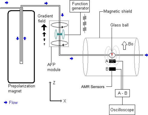
The experimental setup is shown in Fig. 1. Tap water, prepolarized by flowing through a Bruker 17-T magnet, then flows through an adiabatic inversion region where its polarization is periodically reversed, after which it flows past an AMR detector. The adiabatic polarization inverter incorporates a set of coils in anti-Helmholtz configuration to supply a gradient of Bz along the direction of the water flow. A second set of Helmholtz coils is used to apply a 5.5-kHz oscillating field in the x direction, resonant with the protons' Larmor frequency in the center of the inverter. When the oscillating field is on, the proton magnetization is adiabatically reversed as the water flows through the device. Switching the oscillating field on and off results in magnetization either parallel or antiparallel to the bias field. After the adiabatic inverter, the water flows into the detection region, consisting of a 0.5-cm3 glass ball adjacent to a pair of Honeywell HMC1001 AMR sensors arranged as a gradiometer to cancel the common-mode magnetic field noise. The active part of the sensor is a thin film with an area of ≈1.5 × 1.5 mm, packaged in a chip with dimensions 10 × 3.9 × 1.5 mm. The manufacturer's specifications for the HMC1001 sensor give a single-shot resolution of 40 μG with a read-out rate of 1 kHz, corresponding to a sensitivity of , assuming white noise. In our experimental setup, we realized a sensitivity of at 20 Hz (per sensor); however, the low-frequency performance was considerably worse, on the order of at 1 Hz, necessitating signal averaging. The detection region is housed inside a single layer of magnetic shielding with open ends. The water-carrying tube had an i.d. of in, and the flow rate was 3.8 cm3/s, corresponding to an average speed of water of ≈2 m/s. The average travel time from the magnet to the inverter is ≈1.5 s and from the inverter to the detector is ≈0.5 s.
Fig. 1.
Experimental setup. Water is prepolarized by flowing it through the magnet. The magnetization is periodically inverted by passing the liquid through the adiabatic fast passage (AFP) module and is detected with a gradiometer consisting of two AMR sensors.
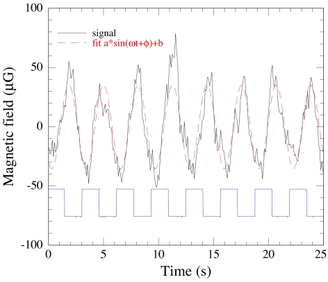
Data were recorded on a digital oscilloscope, averaging for ≈20 min for modulation frequencies in the range 0.3–1.7 Hz. Because there was considerable low-frequency drift in the signal (due to either ambient field drifting or intrinsic drift in the magnetometers), we subtracted from the raw data a slow-varying background approximated by a third-order polynomial. The resulting signal for a modulation frequency of 0.3 Hz is shown in Fig. 2. Neglecting fluid mixing in the transfer tube and detection volume, one would expect that the signal should be a square wave for low modulation frequencies. However, considerable mixing produced signals well approximated (above the cutoff frequency) by a sinusoid, as indicated by the dashed line in Fig. 2.
Fig. 2.
Adiabatic inversion signal (blue trace) and resulting magnetometer signal (black trace) for 0.3-Hz modulation frequency. Overlying the magnetometer signal is a fit to a sinusoidal function. The phase in the fit accounts for the time required for water to travel from the encoding region to the detection region. The lower trace shows the on/off pattern of the adiabatic inverter. The signal was averaged over 20 min.
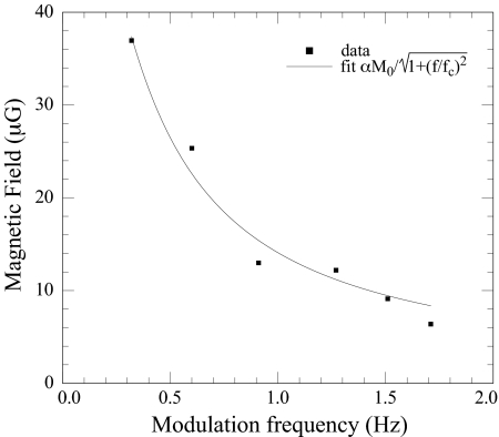
All of the data were fit to sinusoidal profiles, and the resulting amplitudes are shown as a function of frequency in Fig. 3. The rapid drop in amplitude is due to mixing of the magnetization as it propagates from the AFP device through the detection volume, effectively integrating the magnetization. A simple model for the spectral response of the system is that of a low-pass resistive–capacitive filter, where the frequency dependence of the signal is . Here, α is a dimensionless proportionality constant depending on geometry relating the magnetic field at the sensor to the magnetization of the sample, and fc is a cutoff frequency. Overlaying the data in Fig. 3 is a fit to this model function with αM0 = 67 μG and fc = 0.2 Hz.
Fig. 3.
Amplitude of the modulated water signal and a fit to a resistance–capacitance-filter transfer function.
We now briefly consider the performance of an optimized system. If we assume that the sample and sensor are approximately equal in size and located a small distance apart, the field at the sensor is approximately equal to the magnetization M = nμ2B/(kT), where μ is the nuclear magnetic moment of interest, B is the prepolarizing field, and n is the nuclear spin density of the sample. To achieve a SNR of 3 for a sensor with sensitivity δB measuring with bandwidth Δf, we then require a minimum density of nuclei
When measured over a bandwidth of 1 Hz, assuming protons at room temperature, a prepolarizing field of 10 kG (easily produced by permanent magnets) and a sensitivity , we find δn = 6 × 1022 cm−3. If we assume that Eq. 1 is correct for a cubic sample with edges of length 10 μm, this corresponds to a total number of protons δN = 6 × 10¹³. This proton-number sensitivity is similar to the detection limits demonstrated by microcoils in superconducting magnets (10–12). The projected proton-number detection limit of millimeter-scale atomic magnetometers (4) is also similar; however, in that case the density sensitivity is considerably better (≈1017 protons per cubic centimeter).
We suspect that the low-frequency performance of our AMR sensor was limited by the open-ended magnetic shields used in the experiment. Optimization of geometry will lead to substantial gains in signal size by reducing the distance from the sample to the magnetometer, as well as dramatically improved bandwidth (by minimizing the volume of the detected water so that less mixing occurs at high frequencies). In principle, the detected volume could be a microfluidic channel built into the sensor package, similar to the construction in ref. 13 where magnetic microparticles were detected. The higher bandwidth has the additional benefit of moving the signal above the 1/f knee of the sensor. Higher sensitivity and spatial resolution may also be achieved by using an array of sensors, as in ref. 14.
We have demonstrated detection of NMR signals by using an AMR sensor at room temperature. The technique may be useful for spatial localization (MRI), relaxometry, diffusometry, or spin labeling in chemical analysis (15). With anticipated future advances in AMR sensors and related solid-state technologies such as tunneling magnetoresistance (16), solid-state, chip-scale magnetometers may eventually reach the sensitivity level at room temperature (17). Incorporation of built-in microfluidic channels at the chip level will allow the construction of dedicated lab-on-a-chip devices. With these improvements, room-temperature solid-state devices appear to be an inexpensive and robust alternative for detection of both in situ and remote NMR/MRI without the need for cryogenics.
ACKNOWLEDGMENTS.
This work was supported by Office of Naval Research Multidisciplinary University Research Initiative Grant FD-N00014-05-1-0406 and by the Director, Office of Science, Office of Basic Energy Sciences, Nuclear and Materials Sciences Divisions, of the U.S. Department of Energy under Contract DE-AC03-76SF00098.
Footnotes
The authors declare no conflict of interest.
References
- 1.Moulé AJ, et al. Amplification of xenon NMR and MRI by remote detection. Proc Natl Acad Sci USA. 2003;100:9122–9127. doi: 10.1073/pnas.1133497100. [DOI] [PMC free article] [PubMed] [Google Scholar]
- 2.Wong-Foy A, et al. Laser-polarized Xe-129 NMR and MRI at ultralow magnetic fields. J Magn Reson. 2002;157:235–241. doi: 10.1006/jmre.2002.2592. [DOI] [PubMed] [Google Scholar]
- 3.Xu S, et al. Magnetic resonance imaging with an optical atomic magnetometer. Proc Natl Acad Sci USA. 2006;103:12668–12671. doi: 10.1073/pnas.0605396103. [DOI] [PMC free article] [PubMed] [Google Scholar]
- 4.Ledbetter MP, et al. Zero-field remote detection of NMR with a microfabricated atomic magnetometer. Proc Natl Acad Sci USA. 2008;7:2286–2290. doi: 10.1073/pnas.0711505105. [DOI] [PMC free article] [PubMed] [Google Scholar]
- 5.Tsymbal EY, Pettifor DG. Perspectives of giant magnetoresistance. In: Ehrenreich H, Spaepen F, editors. Solid State Physics: Advances in Research and Applications. Vol 56. San Diego: Academic; 2001. pp. 113–237. [Google Scholar]
- 6.Pannetier M, Fermon C, Le Goff G, Simola J, Kerr E. Femtotesla magnetic field measurement with magnetoresistive sensors. Science. 2007;304:1648–1650. doi: 10.1126/science.1096841. [DOI] [PubMed] [Google Scholar]
- 7.Pannetier-Lecoeur M, Fermon C, Biziere N, Scola J, Walliang AL. RF response of superconducting-GMR mixed sensors: Application to NQR. IEEE Trans Appl Supercond. 2007;17:598–601. [Google Scholar]
- 8.Kominis IK, Kornack TW, Allred JC, Romalis MV. A subfemtotesla multichannel atomic magnetometer. Nature. 2003;422:596–599. doi: 10.1038/nature01484. [DOI] [PubMed] [Google Scholar]
- 9.Freitas PP, Ferreira R, Cardoso S, Cardoso F. Magnetoresistive sensors. J Phys Condens Matter. 2007;19:165221–165241. [Google Scholar]
- 10.Olson DL, Peck TL, Webb AG, Margin RL, Sweedler JV. High-resolution microcoil H-1-NMR for mass-limited, nanoliter-volume samples. Science. 1995;270:1967–1970. [Google Scholar]
- 11.Webb A. Nuclear magnetic resonance of mass-limited samples using small RF coils. Anal Bioanal Chem. 2007;388:525–528. doi: 10.1007/s00216-007-1178-2. [DOI] [PubMed] [Google Scholar]
- 12.Minard KR, Wind RA. Picoliter H-1 NMR spectroscopy. J Magn Reson. 2002;154:336–343. doi: 10.1006/jmre.2001.2494. [DOI] [PubMed] [Google Scholar]
- 13.Pekas N, Porter MD, Tondra M, Popple A, Jander A. Giant magnetoresistance monitoring of magnetic picodroplets in an integrated microfluidic system. Appl Phys Lett. 2004;85:4783–4785. [Google Scholar]
- 14.Wood DK, Ni KK, Schmidt DR, Cleland AN. Submicron giant magnetoresistive sensors for biological applications. Sens Actuators A. 2005;120:1–6. [Google Scholar]
- 15.Anwar MS, et al. Spin coherence transfer in chemical transformations monitored by remote detection NMR. Anal Chem. 2007;79:2806–2811. doi: 10.1021/ac062327+. [DOI] [PubMed] [Google Scholar]
- 16.Gomez P, Litvinov D, Khizroev S. A method to design high SNR nanoscale magnetic sensors using an array of tunnelling magneto-resistance (TMR) devices. J Phys D Appl Phys. 2007;40:4396–4404. [Google Scholar]
- 17.Ferreira R, et al. Tuning of MgO barrier magnetic tunnel junction bias current for picotesla magnetic field detection. J Appl Phys. 2006;99 8K706. [Google Scholar]


