Abstract
No technique has been consistently successful in the repair of large focal defects in cartilage, particularly in older patients. Tissue-engineered cartilage grown on synthetic scaffolds with appropriate mechanical properties will provide an implant, which could be used to treat this problem. A means of monitoring loads and pressures acting on cartilage, at the defect site, will provide information needed to understand integration and survival of engineered tissues. It will also provide a means of evaluating rehabilitation protocols. A “sensate” scaffold with calibrated strain sensors attached to its surface, combined with a subminiature radio transmitter, was developed and utilized to measure loads and pressures during gait. In an animal study utilizing six dogs, peak loads of 120N and peak pressures of 11 MPa were measured during relaxed gait. Ingrowth into the scaffold characterized after 6 months in vivo indicated that it was well anchored and bone formation was continuing. Cartilage tissue formation was noted at the edges of the defect at the joint–scaffold interfaces. This suggested that native cartilage integration in future formulations of this scaffold configured with engineered cartilage will be a possibility.
Keywords: scaffolds, sensor, tissue engineering, hydroxy(1)lapatite, articular cartilage
INTRODUCTION
Joint pain and loss of mobility represents the most common cause of impairment in the US patient population.1 Although numerous procedures have been developed for the treatment of damaged articular cartilage, none exist that consistently restore the long term function of articular cartilage.2,3 This may be the reason that of the 500,000 articular cartilage defects diagnosed in 2001, less than 5% were treated with repair techniques.4 Although considered one of the most successful techniques developed to date, autologous chondrocyte implantation (ACI), which involves the harvest of chondrocytes, their extension in culture, and their injection under a periosteal flap attached to the patients cartilage, has shown no marked improvement compared with the results of leaving an empty defect, when studied in an animal model.5 While recent long term clinical follow-up6 suggests that stable tissues with a hyaline-like appearance are visible in 80% of lesions treated with ACI, the quality of the tissue is questionable. Even if this technique offers advantages to selected patients, it currently cannot be effectively applied in older patients or highly loaded areas such as the patellar surface. In addition, it requires long rehabilitation times.7
Tissue-engineered cartilage covered scaffolds offer a potential solution to resurfacing damaged cartilage in both young and old patients who want to remain active.8,9 Earlier studies have shown that porous polymer and calcium phosphate ceramic (CPC) scaffolds can be produced with various pore sizes and shapes and that ingrowth can anchor them in bone.10–14 These early studies primarily described scaffold morphology as a function of production techniques, but did not evaluate the factors affecting ingrowth. In particular, the effect of loading on bone formation around and into scaffold structures has not been examined. Indeed, no study has directly measured in vivo loading experienced by scaffolds, although one study15 punctuated the need for this type of measurement by showing that strains in bench top loaded test coupons made from scaffolds can vary significantly.
Strains due to loading of scaffolds will affect tissue formation and consequently the potential success of both scaffold anchorage and integration of the engineered cartilage tissue with native tissue. A benefit of measuring loading of scaffolds directly in vivo is that it will provide more accurate measurements of loads acting on cartilage during gait and various other activities. Cyclically loading dedifferentiated cells to strains estimated to represent those noted during stance has been shown to induce some degree of cell alignment.16 Cell alignment noted in the layers within cartilage is likely responsible for the stratified tissue structure and is necessary for the growth of functional tissue, which mimics the structure of native articular cartilage. As such, in vivo measurements are beneficial for developing techniques that allow growth of functional tissue-engineered cartilage.
The development of a technique to measure loading in vivo also provides the ability to continuously monitor loading. Currently, no technique exists to monitor loading of implanted tissue-engineered constructs. A scaffold with embedded sensors coupled with a short range transmitter will be able to provide real-time feedback to patients acting as a “sensate” scaffold. A “sensate” scaffold offers the potential for patients to monitor their tissue-engineered cartilage during exercise, allowing them to protect the tissue from activities that may over load it.
It was the goal of this study to develop, calibrate, and test an implantable scaffold load monitoring system and use it in an animal model to collect in vivo load measurements. This is a first step toward developing an implantable cartilage-covered “sensate” scaffold to be used in patients.
METHODS
Scaffold Preparation and Calibration Procedure
Polybutylene terephthalate (PBT) scaffolds were manufactured using an extrusion freeform fabrication rapid prototyping process, which has previously been reported.17 A grid pattern formed with PBT, which had been noted to develop good bone ingrowth in a previous study,18 was modified slightly so that strands within the scaffold were rotated 45° between layers (Figure 1). This pattern provided an interconnected porous structure, which was expected to insure rapid bone ingrowth in vivo. The overall outer shape of the scaffold (Figure 2) was designed with a domed surface on which a cartilage layer could ultimately be grown, a solid layer within the scaffold to act as a barrier to bone through growth (expected to act in the way a subchondral plate acts), and a cylindrical porous bone interfacing region (Figure 2) to encourage bone ingrowth.
Figure 1.
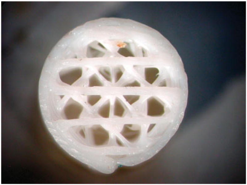
This picture shows the basic strand pattern used in the implanted scaffolds. The outer ring provided confinement of the porous structure and insured reproducible strain transfer to gauges attached to the scaffold surface [Color figure can be viewed in the online issue, which is available at www.interscience.wiley.com.].
Figure 2.
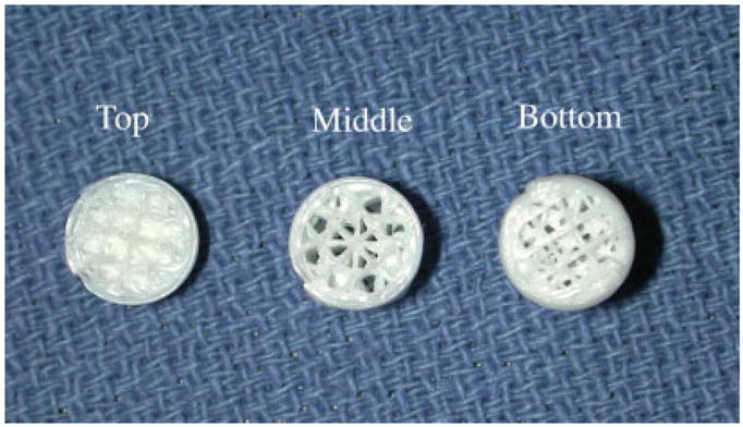
A picture of a representative scaffold, which was sectioned to show the variation in porosity in the bottom and middle sections of the scaffold, and a solid layer below the joint interfacing domed (top) region of the scaffold. [Color figure can be viewed in the online issue, which is available at www.interscience.wiley.com.].
The scaffold design was initially prepared in SolidWorks (Concord, MA), and the data set was exported in stereolithographic format to Quickslice (Microsoft, Redmond, WA), which produced the files that controlled a Statasys FDM 1650 modeler (Statasys, Eden Prairie, MN). The scaffold was built one layer at a time, using a 1.778 mm (0.07 inch) diameter filament created from Valox 312 resin (GE Plastics, Pittsfield, MA), which was heated and extruded through a 0.3048 mm (0.012 inch) tip. The completed scaffold was 8.9 mm in diameter with a cylindrical section that was 11.3 mm long and a domed section that had a radius of curvature of 4.4 mm. Scaffolds had an interconnected pore structure that resulted in an average porosity of (78 ± 2)% when evaluated with the μCT scanner.19
Scaffolds were cleaned with ethanol and deionized water prior to coating the interior pores with β-tricalcium phosphate (TCP) particles, using a published latexing procedure.18 This procedure utilized polycaprolactone (PCL) mixed with sodium dodecylsulfate (Fluka Chemika, Switzerland) in deionized water. The solution was frothed, cooled, centrifuged, and dried prior to blending it with TCP powder (Fluka Chemika, Switzerland) in a 2:1 ratio. A slurry formed from the powder and deionized water was cooled with an ice bath in an ultrasonic cleaner, and scaffolds were dipped into it and then allowed to dry at room temperature. They were baked at 75°C for 12 h, then cleaned with deionized water, 70% ethanol, and finally rinsed in deionized water.
Three 1000 ohm FAE-12–100-S6ET single element strain gauges (Micro-Measurements, Raleigh, NC) were aligned and attached to the surface along the long axis of the scaffold with a 120° separation (Figure 3). This configuration was selected based on bench top testing that showed consistent load determination when this configuration was used to evaluate mid-stance loading.20 The exterior surfaces of scaffolds were coated with a blend of CPC particles (Biointerfaces, San Diego, CA), which have shown favorable bone-to-CPC bonding21 while providing excellent CPC-to-gauge interface strength.22 These coatings have previously been used in long-term animal and clinical strain gauge studies.23,24 This procedure utilized a 15 wt % solution of medical-grade polysulfone (Amoco, Huntington Beach, CA) dissolved in 1,1,2,2-tetrachloroethane (Kodak, Rochester, NY), which was baked at 90°C following application of the CPC particle blend.
Figure 3.
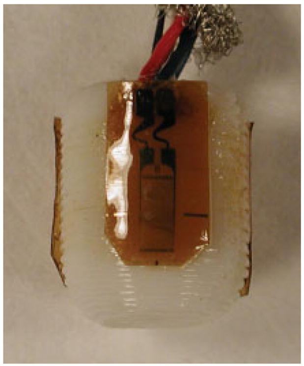
A strain-gauged scaffold showing the gauge locations on a scaffold surface. [Color figure can be viewed in the online issue, which is available at www.interscience.wiley.com.].
Gauges were wired to a cable and waterproofed using a published procedure.23 Scaffolds were loaded in confined compression, using a synthetic bone support, based on experiments,20 indicating that this configuration provided measurements consistent with those collected from scaffolds in joints. Loading was carried out with a servo-hydraulic materials testing system (MTS, MI) at three load rates, 100, 150, and 200 N/s. These rates were chosen to simulate loading at a series of gait speeds. Load vs. strain calibration curves were prepared for each strain-gauged scaffold. Wired scaffolds were cleaned, sterilized using ethylene oxide, and aerated prior to implantation.
Surgical Placement and Monitoring of Scaffold
Six tall male hounds weighing between 29 and 35 kg were selected for implantation surgery. The NIH guidelines for animal care and use were observed during all animal experiments. Following preparation of one hind limb of each of the six hounds, an incision was made exposing the medial femoral condyle and a scaffold was implanted (Figure 4a,b) by drilling two concentric holes, one for the cable and the second for the scaffold. The cable exited the lateral aspect of the femur and was coiled subcutaneously near the trochanter for later retrieval. Following a 3-month holding period, retrieved wires were connected to a male nine pin connector, which could be attached to either a hard wired system or a subminiature radio transmitter system.
Figure 4.
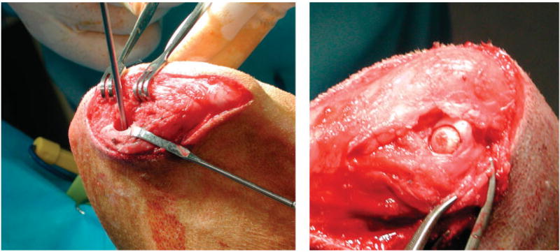
(a) Picture showing a 9-mm hole prepared during surgery for scaffold placement with the guide drill in place. (b) Picture of a scaffold inserted in medial femoral condyle of a dog. [Color figure can be viewed in the online issue, which is available at www.interscience.wiley.com.].
Hard wired measurements were collected using a previously described setup.24 In preparation for measurement collection, the nine pin connector was attached to a mating connector wired to a series of signal conditioners (Vishay, 2300 Strain Gage Conditioners, Measurements Group, Raleigh, NC). Measurements were collected through an NB-MIO-16 Data Translation board (National Instruments, Austin, TX) into a Macintosh G4 computer (Apple, Cupertino, CA) running LabView Version 5 (National Instruments, Austin, TX). After zeroing and calibrating each channel, each animal was walked on a Trotter variable speed inclining treadmill (United Medical Company, Millis, MA), which was oriented horizontally and run at speeds up to 2.54 m/s (5.7 mph) while strain measurements were collected. Calibration curves were used to assess loading from the strain measurements. Measurements were also collected using a subminiature telemetry unit following a previously described procedure, which had been utilized to collect measurements from a patient.25 Data collection was carried out using custom data acquisition and analysis software running on a Macintosh G3 laptop computer. A power coil, tuned to the frequency of the pickup coil on the transmitter unit, was energized. Once a signal had been established from the transmitter, measurements were collected into Excel spreadsheets and saved for later analysis.
All dogs were exercised daily and were allowed food and water ad libidum. Twenty days prior to sacrifice, 15 mg/kg doses of tetracycline were administered orally 3 times a day, for 3 days. This procedure was repeated 10 days after the completion of the first dosing cycle, creating bone labels with a 10 day separation. Following 6 months of in vivo monitoring, animals were euthanized, and their bones were explanted.
Bench Top Testing Procedure
Explanted bones were loaded as part of a bench top testing experiment, which has previously been reported.20 As part of the procedure, both hind limbs of each dog were removed and the stifle joints excised, leaving the capsules and soft tissues in the region of the joint intact. Femurs and tibias were cut and mounted on fixtures attached to an MTS. Low pressure, high sensitivity Fuji film (Pressurex, Hanover, NJ) was placed into both medial and lateral compartments of the menisco-femoral joints and a load was applied at a rate of 200 N/s at 30°, 50°, and 70° flexion, to simulate paw strike, stance, and toe off during gait. Five impressions were taken at each angle, scanned, and processed. Films were scanned using a LaCie Silverscanner II (LaCie, France). ImageJ 1.28 v (National Institutes of Health, Bethesda, MD) was used following a published procedure20,26 to determine scaffold contact areas to assess contact pressures from in vivo load data.
Joint Preparation, Histology and Image Collection
Prior to mechanical testing, both the control and experimental, explanted stifle joints were radiographed with a Faxitron high resolution cabinet X-ray unit (Hewlett Packard, CA). In each case, a lateral and an AP radiograph were taken to accurately identify the location of the scaffold in the joint. Films were digitized by photographing them with a Nikon Coolpix 990 camera (Nikon, Tokyo, Japan).
The stifle joints were separated after mechanical testing by transecting the ligaments and patellar tendon. All soft tissues were carefully removed with a scalpel and gross images of femoral surfaces and tibial plateaus were collected. The medial femoral condyles and the medial tibial plateaus of the joints were separated and dehydrated using a published procedure27 utilizing sequentially higher concentrations of ethanol solutions beginning with a 70% solution. Following complete dehydration, both the experimental and the control femoral condyles were embedded in poly-methyl methacrylate.27,28
A sagittal section was taken through the embedded joints, using a diamond waffering saw (Bronwill Industries, Rochester, NY). This section separated the medial from the lateral condyles. Next, up to five slices were made in the sagittal plane through the middle of the scaffold to provide a reasonable representation of bone in and around the scaffold. Using a Reickert-Jung Polycut-e and an Ultra milling machine (Cambridge Instruments, Germany), the sections were milled to a section thickness of 100 μm and polished to a 0.05 μm finish. Sections of the control knee were prepared in the same manner. Care was taken to cut slices from the identical locations to those cut on the experimental femur.
Sections were stained with a mineralized bone stain, M.I.B.S. (Harrington Center, Phoenix, AZ) and were photographed at 1.4 × original magnification using transmitted light and 2.8 × original magnification, using fluorescent light, through a Nikon Optiphot microscope (Nikon, Tokyo, Japan) with an Olympus MagnaFire SP digital image viewing and recording system (Olympus, Tokyo, Japan) and saved in Adobe Photoshop (Adobe, San Jose, CA). A slide micrometer was placed in each photograph to insure accurate measurement of characteristic parameters during histomorphometry. Measurements from transmitted light images were taken at 62.5 × magnification. Measurements from fluorescent light images were taken at 125 × magnification, using the same setup.
Histomorphometry
Gross bone area and perimeter measurements were catalogued with respect to designated areas that they were measured from (Figure 4). These areas were (1) the spaces in the scaffold, (2) the periscaffold space around the perimeter of the scaffold, (3) the deep periscaffold space behind the scaffold, and (4) the superficial space (containing the joint surface). The periscaffold space was outlined 1 mm from the edge of the scaffold. The deep periscaffold space was delineated by drawing a line parallel to the scaffold 1 mm from its back edge (Figure 5). Measurements were collected in the control bone, from a comparable area of the same size and shape as that measured in the experimental bone.
Figure 5.
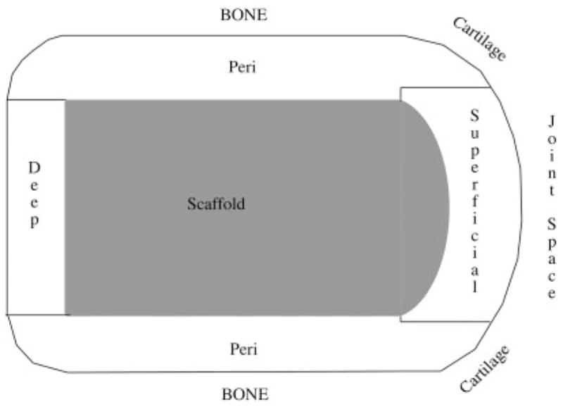
This drawing shows a schematic diagram with a cross-sectional side view of the four regions in which histmorphometry measurements were collected from both the experimental and control slides.
Images were imported into Image J and the edges of each region were marked. Next, the areas and perimeters from experimental and control slices were measured and tabulated. Bone, soft tissue and marrow space (Table I) were measured.
TABLE I.
Bone Volume, Marrow Volume, and Osteoid Volume are Reported Normalized Relative to the Total Volume. The p Values in the Far Right Column Indicate Whether a Significant Difference Exists Between the Experimental and Control
| Control Limb | Experimental | p Values | |
|---|---|---|---|
| Scaffold | |||
| BV/TV (%) | 35.2 ± 5.2 | 6.8 ± 8.8e | < 0.005 |
| MaV/TV (%) | 63.2 ± 5.3 | 28.2 ± 13.2 | < 0.005 |
| OsV/TV (%) | 0.9 ± 0.8 | 64.9 ± 17.2 | < 0.005 |
| Periscaffold | |||
| BV/TV (%) | 36.3 ± 3.9 | 59.5 ± 9.5 | < 0.005 |
| MaV/TV (%) | 62.8 ± 4.1 | 8.7 ± 6.2 | < 0.005 |
| OsV/TV (%) | 0.9 ± 0.7 | 31.8 ± 10.0f | < 0.005 |
| Deep | |||
| BV/TV (%) | 27.3 ± 6.6a | 27.2 ± 11.0 | < 0.6 |
| MaV/TV (%) | 72.7 ± 6.6 | 17.3 ± 10.3 | < 0.005 |
| OsV/TV (%) | 0.0 ± 0.0b | 55.6 ± 19.1 | < 0.005 |
| Superficial | |||
| BV/TV (%) | 43.4 ± 7.2 | 18.6 ± 13.3 | < 0.01 |
| MaV/TV (%) | 25.9 ± 9.0c | 1.6 ± 1.2c | < 0.01 |
| OsV/TV (%) | 30.7 ± 15.1d | 79.7 ± 14.4 | < 0.01 |
Cells in which values are in italic and marked with lower case letters show significant differences in values determined in one area relative to the other three areas.
BV, Bone Volume; MaV, Marrow Volume; OsV, Osteold Volume; TV, Total Volume.
– BV/TV, lower in deep scaffold area ( p < 0.01);
– MaV/TV, lower in joint space ( p < 0.001);
– OsV/TV, lower in deep scaffold area ( p < 0.001);
– OsV/TV, higher in joint space ( p < 0.001);
– OsV/TV, lower in periscaffold region ( p < 0.005);
– BV/TV, lower in scaffold area ( p < 0.01)
Measurements collected from within the scaffold, the periscaffold, deep-scaffold, and superficial scaffold regions included the total volume (measured as the area enclosed within the outer bone perimeter), bone volume (calculated as the total volume less the area enclosed within the marrow space and soft tissue space), soft tissue volume, and marrow volume as well as the perimeters of these components. In addition, the single label length, outer and inner double label length, and interlabel distance were measured. The total labeled distance was calculated as the single label length plus the average of the inner and outer double label lengths. The percent labeled surface was calculated as half of the single label distance + the average of the inner and outer double label distance. The mineral apposition rate (MAR, μm/day) was calculated as the distance between the center of the inner and outer labels divided by the number of days between the administration of the tetracycline. The bone formation rate (BFR, μm2/μm3/day) was calculated as the MAR multiplied by the total labeled distance divided by the bone perimeter.
Data was characterized for skewness and kurtosis. Because kurtosis was noted in some parameters, a Krustkal-Wallis test was used to determine statistical significance. The scaffold, periscaffold, deep, and superficial regions were compared between control and experimental limbs. In addition, regions within each limb were compared. The threshold for statistical significance was set at p ≤ 0.05.
RESULTS
In Vivo Strain Measurements and Stifle Loads
Strain vs. load curves for gauged scaffolds were noted to be linear up to the peak test load during calibration (Figure 6). In vivo strain patterns were similar in shape to patterns collected from the mid-diaphysis of the femora of dogs during earlier in vivo studies. Each gait cycle contained a low load during swing phase, which was assigned the zero strain value. Load vs. time graphs, converted by using calibration curves for each scaffold, indicated that peak loads ranged from ~ 80 to 120 N during gait (Figure 7). This indicated that up to 35% of the dogs body weight was acting on its hind limb during relaxed gait. The length of swing phase (during which loads are at a minimum) was ~ 0.2 s and the length of mid stance (during which loads peaked) was ~ 0.4 s. Peak strain measurements collected using hardwired and radio telemetry systems during gait were within 5 microstrain and strain patterns were visually identical.
Figure 6.
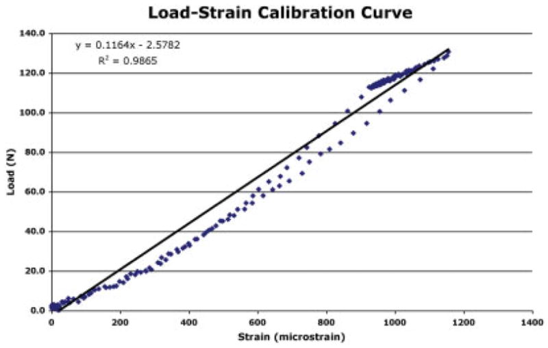
Load vs. strain calibration curve for a representative gauge on one of the scaffolds. Curves were used to translate in vivo strain measurements into loads. [Color figure can be viewed in the online issue, which is available at www.interscience.wiley.com.].
Figure 7.
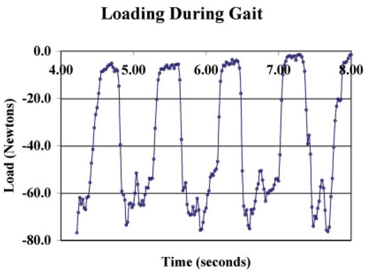
Representative graph of load measurements during gait from the stifle joint of dog. Repeated collection of these loads over several weeks produced the same patterns and the same peak loads within each dog. [Color figure can be viewed in the online issue, which is available at www.interscience.wiley.com.].
When raised to stand only on their hind limbs, a 260% increase in peak load was observed during two-legged walking. As expected, load rates also increased while swing phase and stance phase times decreased in length.
A load of 65 ± 6.5 N was recorded while animals stood relaxed prior to and following gait measurements. This indicated that ~ 40% of the dogs body weight was acting on its two hind limbs. Passive loading of the hind limb containing the scaffold produced loads of the same magnitude as stance. Loads were noted to be a function of knee flexion, with higher loads observed at high flexion angles.
Post Sacrifice Testing
On the basis of a calculated contact area of the scaffold surface with cartilage, contact stresses (pressures) were estimated to be between 4 and 6 MPa for peak loads measured during gait. Post sacrifice Fuji film measurements of loaded joints containing scaffolds at 30° flexion (which represented the angle at which the scaffold was most clearly loaded) were 7.26 ± 1.0 mm2, which indicated that peak in vivo contact pressures in the medial compartment were actually as high as 11.0 ± 1.54 MPa during gait.
Gross examination of knee surfaces in the explanted hind limbs showed that scaffolds were adequately recessed but mild scoring of the tibial cartilage was noted in some animals (Figure 8). Scaffolds appeared to be securely fixed with no visible adverse reaction to the scaffold material. Cables were surrounded by a thin fibrous tissue layer, which prevented them from migrating.
Figure 8.
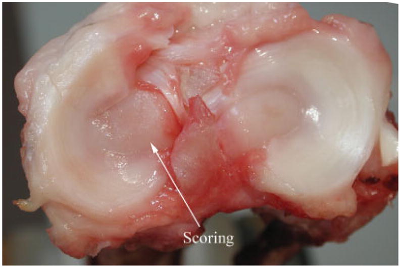
Picture showing a tibial surface with a rare case of minor scoring caused by a scaffold. [Color figure can be viewed in the online issue, which is available at www.interscience.wiley.com.].
Histology and Scanning Electron Microscopy
There was an overall increase in the soft tissue volume seen in the experimental stifle compared with the control in all regions (Table I). The increased amount of soft tissue in the marrow cavity space (Figure 9) resulted in a relatively lower marrow cavity volume measurement in the experimental knees. The average % surface area of the scaffold dome (in the superficial space) that was covered by soft tissue was (67.7 ± 19.7)%, and the dome was covered primarily with cartilage and some fibrous tissue. There were regions of cartilage tissue overlying the dome that contained large numbers of chondroblasts (Figure 10). In general, the tissue over the center of the dome was more fibrous than that near the edges, which resembled cartilage and contained chondroblasts.
Figure 9.
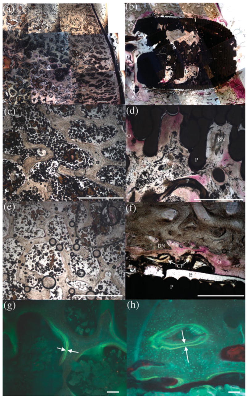
(a) and (b) are representative images portraying overall layout and composition of both control and experimental slides, respectively, at 6 months post-op. Magnified images of the experimental scaffold region revealed less bone volume (d) than the control (c). The experimental periscaffold region (f) presented significantly more bone volume and a wider double label distance (h) than the control (e and g). Within each image, (BN) indicates bone; (CP) represents CPC particles; (E) marks epoxy; (O) denotes osteoid; and (P) signifies the PBT scaffold. Scale bar is 1mm in (a) through (f) and 100 μm in (g) and (h). [Color figure can be viewed in the online issue, which is available at www.interscience.wiley.com.].
Figure 10.
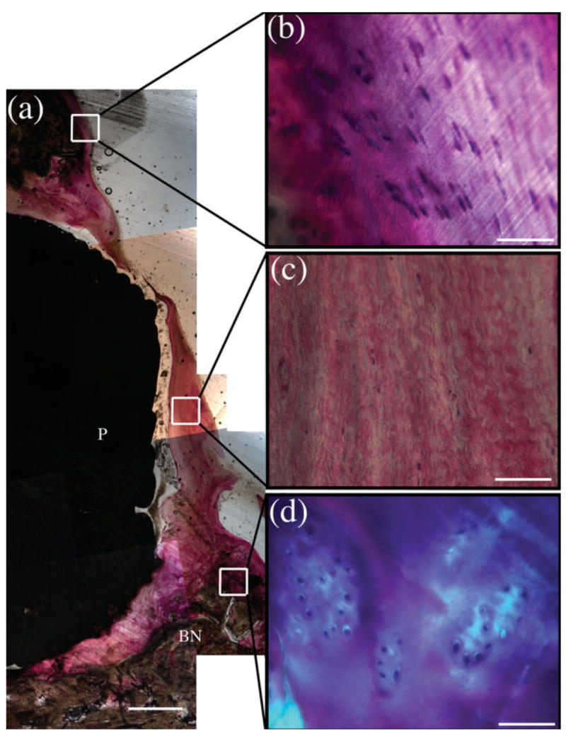
The superficial scaffold region showing the scaffold dome and overlying cartilage (a) with magnified images of normal cartilage (b), the fibrous tissue directly superficial to the dome of the scaffold (c), and large lacunae filled with chondroblast-like cells near the edge of the scaffold dome (d). Within the images, (BN) designates bone with (P) representing the PBT scaffold. Scale bar is 1 mm in (a) and 50 μm in the remaining images. [Color figure can be viewed in the online issue, which is available at www.interscience.wiley.com.].
While the soft tissue and marrow cavity volumes were similar in all regions, the bone volume was highly dependant on the region of the scaffold. The bone volume was significantly decreased within the scaffold relative to controls (Figure 9, image D); however, it was increased in the periscaffold region (Figure 9, image F). In both the scaffold and periscaffold regions, there was a significant increase in the bone formation rate (Table I). The increase within the scaffold was due to an increased amount of labeled surface (Figure 9 and Table II) whereas in the periscaffold region, it was due to both an increase in the amount of labeled surface and an increased mineral apposition rate.
TABLE II.
Histomorphometry From Control and Implanted (Experimental) Limbs. The p Values in the Far Right Column Indicate Whether a Significant Difference Exists Between the Experimental and Control
| Control Limb | Experimental | p Values | |
|---|---|---|---|
| Scaffold | |||
| MAR (um/day) | 0.0007 ± 0.0004 | 0.0010 ± 0.0008 | 0.9 |
| Lbl sur (%) | 1.7 ± 0.5 | 5.4 ± 2.8 | 0.05 |
| BFR/BS | 1.3E-5 ± 0.8E-5 | 8.2E-5 ± 5.9E-5 | 0.05 |
| Periscaffold | |||
| MAR (um/day) | 0.0009 ± 0.0005 | 0.0015 ± 0.0007 | 0.05 |
| Lbl sur (%) | 1.7 ± 0.9 | 10.5 ± 8.7 | 0.05 |
| BFR/BS | 1.7E-5 ± 0.9E-5 | 1.8E-4 ± 1.6E-4 | 0.01 |
| Deep | |||
| MAR (um/day) | 0.0006 ± 0.0003 | 0.0018 ± 0.0013 | 0.1 |
| Lbl sur (%) | 2.5 ± 1.7 | 8.9 ± 6.3 | 0.1 |
| BFR/BS | 2.2E-5 ± 1.9E-5 | 2.0E-4 ± 2.1E-4 | 0.1 |
| Superficial | |||
| MAR (um/day) | 0.0007 ± 0.0003 | 0.0006 ± 0.0009 | 0.6 |
| Lbl sur (%) | 1.6 ± 1.2 | 7.2 ± 6.2 | 0.05 |
| BFR/BS | 1.1E-5 ± 1.1E-5 | 0.8E-5 ± 1.5E-4 | 0.7 |
MAR, Mineral Apposition Rate; Lbl, Labeled Surface; BFR, Bone Formation Rate; BS, Bone Surface.
In addition to comparing the control to the experimental stifle, different regions within each limb were analyzed to detect differences. Within the control stifles, no differences were noted in the scaffold and periscaffold regions (Figure 9, images C and E); however, the deep scaffold space had a lower bone and soft tissue volume (Table I). The superficial region of the scaffold contained significantly more soft tissue than other regions. This was primarily due to the amount of cartilage in this region. Within the experimental stifles, there was less bone within the scaffold (Figure 9, image D) and there was an increased amount of soft tissue within the periscaffold region (Figure 9, image F). There were no significant differences in histomorphometric parameters when comparing the regions within just the control or within just the experimental stifles (Tables I and II).
Histomorphometry indicated that mineral apposition rate and bone formation rate were significantly higher in the sections from the experimental limbs (Table II). It also indicated continued bone formation adjacent to the scaffold with 5 times the amount of labeled surface within the scaffold (Table II). This confirmed that bone formation was widespread in this region of the scaffold.
Scanning electron micrographs of various regions of the scaffolds showed direct bone apposition to inner regions of scaffolds and CPC particles coating the outer scaffold surfaces (Figure 11). Although the inner scaffold surfaces were coated with a TCP layer prior to implantation, no TCP particles were observed on any sections.
Figure 11.
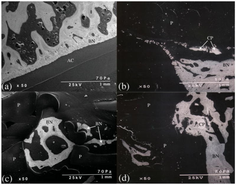
Backscatter electron microscopy images of the superficial scaffold region of the control (a) and the experimental (b) joints. (c) is an image from within the scaffold region of an experimental stifle demonstrating bone (BN) within a PBT (P) pore. (d) shows bone surrounding a CPC particle (CP) and growing up to the scaffold edge as well as bone within a PBT pore. AC, articular cartilage. [Color figure can be viewed in the online issue, which is available at www.interscience.wiley.com.].
DISCUSSION
In order for scaffolds instrumented with strain sensors to be useful in the determination of loads and contact stresses acting on cartilage, a clear reproducible relationship between in vivo strain measurements and loads is essential. The scaffold design reported in this study had a linear load strain relationship allowing straightforward determination of loads from strain measurements. The use of a containment ring around the porous section of the scaffold to which strain gauges were securely attached may account for this reproducible relationship.
Load measurements collected from strain-gauged scaffolds were in agreement with published evidence29,30 showing that, during relaxed gait, 30 – 40% of the dogs body weight is on it’s hind limb. Peak loads increased during rapid gait and increased substantially during two-legged stance and gait. It is noteworthy that loads equivalent to stance phase loads during relaxed gait were observed during passive flexion. As such, this experimental procedure could be used to monitor and control loading in a model utilized to study the effects of passive loading on healing of cartilage tissue.
Bench top loading of explanted limbs with scaffolds indicated contact areas on scaffold surfaces in the medial compartment of joints were similar to those in the lateral compartment. Measurements indicated that scaffold surfaces were not in complete contact i.e. measured surface areas were less than areas calculated assuming complete contact. As a consequence, peak pressures in excess of 11 MPa were noted. These peak pressures are comparable to peak pressures of 12.3 MPa previously reported31 by Nelson et al. in the vicinity of defects drilled in canine condyles and assessed using an India ink staining technique to measure contact areas and determine pressures. In that study, a range of loads encompassing those utilized in our study were used. However, they loaded their knee specimens at a 40° flexion angle. Their measurements31 were in agreement with our observations, which showed that as bench top loads increased, pressures also increased. This observation has also been reported when testing artificial joint contact pressures.26
Pressures reported here are higher than measurements collected in vitro by Brown et al.32 from normal intact canine knees (6.4 ± 2.6 MPa), which were loaded at 40° flexion to 3 times body weight in a tenth of a second. However, their measurements from the edge of defects with a similar diameter to the scaffold used in our study peaked at a maximum pressure nearly double (20 MPa) those we recorded (11 MPa). Pressures determined in this study were also higher than those in a preliminary in vitro study reported by Bliss and coworkers20 (in the range of 2.4 MPa). Although the same in vitro loading procedure described in this study was used, loads measured from strain-gauged scaffolds were much smaller20 than those observed in this combined in vivo and in vitro study.
Similarities and differences between these results suggest that in vivo load measurements are a valuable tool in developing a better understanding of surface pressures, with the added advantage of providing continuous monitoring. This technique can provide measurements that aid in the development of better bench top models of joint loading. In addition, it will be useful in experiments in which physiologic pressures are applied to engineered cartilage-like tissues grown on scaffolds and it will allow monitoring of joint pressures during healing. This will provide insight into consequent successes or failures of the engineered tissues. The results also indicate that, at least at this stage in the development of this technique, post sacrifice testing is essential before reporting pressure measurements.
To allow long-term monitoring of tissues in vivo, a stable measurement transmission system is also valuable. The telemetry system utilized for this study provided peak strain measurements that were essentially identical to hard wired measurements, in agreement with previous reports on this system.25 It was noted to function well when the exciting coil was accurately aligned on the skin with the transmitter coil (below the skin), but stopped transmitting when the power coil was misaligned. Future formulations may benefit from a larger external coil and a coil power monitoring device to insure continuous powering of the system. Monitoring of loads over a period of weeks provided an indication of the consistency of the output signal and indicated that this system can be used over extended periods. However, it was noted that gradual resistance increases shortened the time that measurements could be collected from some of the gauges. These increases may have been caused by scaffold swelling or fluid infiltration into cables, and techniques must be developed to offset changes so that they do not incapacitate the measurement system in the long term. A circuit rebalancing procedure is now being tested, and shows promise in reducing failures caused by the inability to balance the monitoring system.
As expected from previous studies,18 this scaffold system encourages bone growth around and into the pores of these scaffolds. The increased bone volume in the periscaffold region provides an indication that bone has anchored these scaffolds to the surrounding native tissue. The high degree of bone-to-scaffold contact noted using histology and scanning electron microscopy correlated well with the in vivo results, which demonstrated strain transfer through these scaffolds during both the stance phase of gait as well as during passive flexion of the knee. In contrast to the periscaffold region, the bone volume was lower within the scaffold pores. Despite a lower bone volume, the large amount of osteoid tissue and the increased bone formation rate demonstrated within the pores indicates that further bone ingrowth and attachment are still occurring at 6 months post operation. In addition, there was a similar increase in soft tissue volume and bone formation rate noted in the periscaffold region, indicating that additional tissue growth around the scaffold is still occurring.
In general, the soft tissue component within the scaffold pores and in the periscaffold region had a large component of osteoid. In the deep scaffold region, the soft tissue component consisted of a larger amount of fibrous tissue compared with osteoid, especially in sections that contained wires. A likely reason for this is the motion of the wires during gait. CPC coating the wires in future studies will reduce this motion by encouraging bone bonding and integration of the wires into the local bone’s structure. Despite the amount of fibrous tissue in the deep scaffold region, bone growth from the deep scaffold region into the scaffold was noted. Bone growth from the deep scaffold region into the scaffold pores appeared to be less pronounced than bone growth into the scaffold from pores in the periscaffold region.
In the superficial scaffold region, the soft tissue overlying the dome of the scaffold became more fibrous near the center of the scaffold. This was expected as no cartilage-derived cells, engineered tissue, or growth inducing factors were applied to the superficial surface of the scaffold in this study. Near the perimeter of the scaffold at the interface between the implant and the native tissue, there was proliferation of chondroblast-like cells surrounded by thick cartilage-like tissue. This indicates that this scaffold system allows for some cartilage regeneration near the tissue implant interface. This limited regeneration will be beneficial in future studies aimed at integrating a scaffold with a tissue-engineered cartilage on the superficial surface with the surrounding native cartilage.
Analysis of the various regions within the control knee was performed to assess whether expected differences in tissue composition were noted. As expected, there was no change in tissue composition between the scaffold and periscaffold regions within the control knee, and there was a decrease in the bone volume in the deep scaffold region (which was below the subchondral plate). In addition, there was less marrow cavity space and more soft tissue noted in the superficial scaffold region. These observations allowed clear analysis of differences noted relative to the experimental joints.
In summary, bone ingrowth securely anchored the CPC-coated porous PBT scaffolds developed in this study and ingrowth was continuing after 6 months post operation. Strain gauges attached to the surface of scaffolds showed a linear elastic load–strain response, which provided an accurate determination of in vivo loads during gait from strain measurements. Studies using cartilage-covered “sensate” scaffolds, in which loads acting on healing tissues can be monitored, and which were beyond the scope of this study are now possible. Development of a new zeroing technique, better waterproofing techniques, and better coatings between lead wires and transmitters indicate that reliable load measurements can be collected for a substantial length of time and that in combination with post sacrifice histology, these measurements will provide the ability to evaluate the impact of loads on engineered tissue incorporation and survival.
Acknowledgments
Contract grant sponsor: NIH-NIBIB; contract grant number: RO1-EB000660
Contract grant sponsor: NSF-BES; contract grant number: BES 0427483
References
- 1.Buckwalter JA, Mankin HJ. Articular cartilage: Degeneration and osteoarthritis, repair, regeneration, and transplantation. AAOS Instr Course Lect. 1998;47:477–486. [PubMed] [Google Scholar]
- 2.Hunziker EB. Articular cartilage repair: Basic science and clinical progress. A review of the current status and prospects. Osteoarthritis Cartilage. 2002;10:432–463. doi: 10.1053/joca.2002.0801. [DOI] [PubMed] [Google Scholar]
- 3.Woodfield TBF, Malda J, de Wijn J, Peters F, Riesle J, van Blitterswijk CA. Design of porous scaffolds for cartilage tissue engineering using a three-dimensional fiber-deposition technique. Biomaterials. 2004;25:4149–4161. doi: 10.1016/j.biomaterials.2003.10.056. [DOI] [PubMed] [Google Scholar]
- 4.Millenium Research Group Inc. US markets for orthopedic biomaterials, USBO 01. Millenium Group; Toronto, Ontario: 2002. www.mrg.net. [Google Scholar]
- 5.Breinan HA, Minas T, Hsu HP, Nehrer S, Shortkroff S, Spector M. Autologous chondrocyte implantation in a canine model: Change in composition of reparative tissue with time. J Orthop Res. 2001;19:482–492. doi: 10.1016/S0736-0266(00)90015-9. [DOI] [PubMed] [Google Scholar]
- 6.Peterson L, Brittberg M, Kiviraanta I, Akerlund EL, Lindahl A. Autologous chondrocyte transplantation. Biomechanics and long-term durability. Am J Sports Med. 2002;30:2–12. doi: 10.1177/03635465020300011601. [DOI] [PubMed] [Google Scholar]
- 7.Brittberg M, Tallheden T, Sjogren-Jansson E, Lindahl A, Peterson L. Autologous chondrocytes used for articular cartilage repair: An update. Clin Orthop Relat Res. 2001;391(Suppl):S337–S348. doi: 10.1097/00003086-200110001-00031. [DOI] [PubMed] [Google Scholar]
- 8.Grande DA, Breitbart AS, Mason J, Paulino C, Laser J, Schwartz RE. Cartilage tissue engineering: Current limitations and solutions. Clin Orthop Relat Res. 1999;367(Suppl):S176–S185. doi: 10.1097/00003086-199910001-00019. [DOI] [PubMed] [Google Scholar]
- 9.Solchaga LA, Goldberg VM, Caplan AI. Cartilage regeneration using principals of tissue engineering. Clin Orthop Relat Res. 2001;391(Suppl):S161–S170. doi: 10.1097/00003086-200110001-00016. [DOI] [PubMed] [Google Scholar]
- 10.Nam YS, Park TG. Biodegradable polymeric microcellular foams by modified thermally induced phase separation method. Biomaterials. 1999;20:1783–1790. doi: 10.1016/s0142-9612(99)00073-3. [DOI] [PubMed] [Google Scholar]
- 11.Kuo CK, Ma PX. Ionically cross linked alginate hydrogels as scaffolds for tissue engineering: Part 1 Structure, gelation rate and mechanical properties. Biomaterials. 2001;22:511–521. doi: 10.1016/s0142-9612(00)00201-5. [DOI] [PubMed] [Google Scholar]
- 12.Gomes ME, Ribeiro AS, Malafaya PB, Reis RL, Cunha AM. A new approach based on injection moulding to produce biodegradable starch-based polymeric scaffolds: Morphology, mechanical and degradation behavior. Biomaterials. 2001;22:883–889. doi: 10.1016/s0142-9612(00)00211-8. [DOI] [PubMed] [Google Scholar]
- 13.Deng M, Uhrich KE. Effects of in vitro degradation on properties of poly(DL-lactide-co-glycolide) pertinent to its biological performance. J Mater Sci Mater Med. 2002;13:1091–1096. doi: 10.1023/a:1020361109859. [DOI] [PubMed] [Google Scholar]
- 14.Zhang R, Ma PX. Biomimetic polymer/apatite composite scaffolds for mineralized tissue engineering. Macromol Biosci. 2004;4:100–111. doi: 10.1002/mabi.200300017. [DOI] [PubMed] [Google Scholar]
- 15.Nicolella DP, Slivka MA, Leatherbury NC, Niederauer GG, Boyan B. Quantification of tissue scaffold structural strains. Trans Soc Biomaterials Providence RI. 1999;25:80. [Google Scholar]
- 16.Neidlinger-Wilke C, Grood E, Claes L, Brand R. Fibroblast orientation to stretch begins within three hours. J Orthop Res. 2002;20:953–956. doi: 10.1016/S0736-0266(02)00024-4. [DOI] [PubMed] [Google Scholar]
- 17.Vaidyanathan RK, Green C, Bourque P, Calvert PD, Szivek JA, Maxian SH. Strong porous polymer-ceramic composites by rapid prototyping for resorbable orthopedic scaffold applications. Trans Soc Biomaterials, Tampa FL. 2002;28:699. [Google Scholar]
- 18.Szivek JA, Margolis DS, Garrison BK, Nelson E, Vaidyanathan RK, DeYoung DW. TGF-β1 enhanced TCP-coated sensate scaffolds can detect bone bonding. J Biomed Mater Res-B. 2005;73–1:43–53. doi: 10.1002/jbm.b.30177. [DOI] [PMC free article] [PubMed] [Google Scholar]
- 19.Tellis BC, Szivek JA, Bliss CL, Vaidyanathan R. Polymeric Scaffolds from microCT Scans: Joint Specific Solutions for Tissue Supports. Trans Orthopaedic Res Soc, Chicago IL. 2006 March;31:838. [Google Scholar]
- 20.Szivek JA, Bliss CL, Schnepp AB, Ruth JT. Determination of contact pressures in the canine stifle joint. Trans World Biomaterials Congress, Sydney, Australia. 2004;7:1254. [Google Scholar]
- 21.Battraw GA, Szivek JA, Anderson PL. Interface strength studies of calcium phosphate ceramic strain gauges. J Biomed Mater Res (Applied Biomater) 1998;43:462–468. doi: 10.1002/(sici)1097-4636(199824)43:4<462::aid-jbm14>3.0.co;2-j. [DOI] [PubMed] [Google Scholar]
- 22.Battraw GA, Szivek JA, Anderson PL. Bone bonding strength of calcium phosphate ceramic coated strain gauges. J Biomed Mater Res (Applied Biomater) 1999;44:32–35. doi: 10.1002/(sici)1097-4636(1999)48:1<32::aid-jbm7>3.0.co;2-x. [DOI] [PubMed] [Google Scholar]
- 23.Szivek JA, Johnson EM, Magee FP. An in vivo strain analysis of the greyhound femoral diaphysis. J Investig Surg. 1992;5:91–108. doi: 10.3109/08941939209012426. [DOI] [PubMed] [Google Scholar]
- 24.Szivek JA, Anderson PL, DeYoung D. In vivo strain measurements collected using calcium phosphate ceramic bonded strain gauges. J Investig Surg. 1997;10:263–273. doi: 10.3109/08941939709032165. [DOI] [PubMed] [Google Scholar]
- 25.Szivek JA, Roberto R, Slack JM, Majeed BSM. An implantable strain measurement system designed to detect spine fusion: Preliminary results from a biomechanical and in vivo study. Spine. 2002;27:487–497. doi: 10.1097/00007632-200203010-00009. [DOI] [PubMed] [Google Scholar]
- 26.Szivek JA, Anderson PL, Benjamin JB. Average and peak tibio–femoral contact stress and stress distribution evaluation of total knee replacements. J Arthroplasty. 1996;11:952–963. doi: 10.1016/s0883-5403(96)80137-9. [DOI] [PubMed] [Google Scholar]
- 27.Emmanual J, Hornbeck C, Bloebaum RD. A polymethyl-methacrylate method for large specimens of mineralized bone with implants. Stain Tech. 1987;62:401–410. doi: 10.3109/10520298709108030. [DOI] [PubMed] [Google Scholar]
- 28.Martini F, Leichtle U, Lebherz C. Optimierte polymethyl-methacrylate einbettung ermoglicht exacte schnittuntersuchung proximaler femora mit zementfreier endoprothese. Z Orthop Ihre Grenzgeb. 2001;139:531–535. doi: 10.1055/s-2001-19236. [DOI] [PubMed] [Google Scholar]
- 29.Kimura T, Endo B. Comparison of force of foot between quadrupedal walking of dog and bipedal walking man. J Faculty Sci, Univ Tokyo, Sect V(Anthropology) 1972;IV(2):119–130. [Google Scholar]
- 30.Budsberg SC, Verstraete MC, Soutas-Little RW. Force plate analysis of the walking gait in healthy dogs. Am J Vet Res. 1987;48:915–918. [PubMed] [Google Scholar]
- 31.Nelson BH, Anderson DD, Brand RA, Brown TD. Effect of osteochondral defects on articular cartilage: Contact pressures studied in dog knees. Acta Orthop Scand (Denmark) 1988;59:574–579. doi: 10.3109/17453678809148788. [DOI] [PubMed] [Google Scholar]
- 32.Brown TD, Pope DF, Hale JE, Buckwalter JA, Brand RA. Effects of osteochondral defect size on cartilage contact stress. J Orthopaedic Res. 1991;9:559–567. doi: 10.1002/jor.1100090412. [DOI] [PubMed] [Google Scholar]


