Abstract
Porous polybutylene terephthalate (PBT) scaffold systems were tested as orthopedic implants to determine whether these scaffolds could be used to detect strain transfer following bone growth into the scaffold. Three types of scaffold systems were tested: porous PBT scaffolds, porous PBT scaffolds with a thin β-tricalcium phosphate coating (LC-PBT), and porous PBT scaffolds with the TCP coating vacuum packed into the scaffold pores (VI-PBT). In addition, the effect of applying TGF-β1 to scaffolds as an enhancement was examined. The scaffolds were placed onto the femora of rats and left in vivo for 4 months. The amount of bone ingrowth and the strain transfer through various scaffolds was evaluated by using scanning electron microscopy, histology, histomorphometry, and cantilever bend testing. The VI-PBT scaffold showed the highest and most consistent degree of mechanical interaction between bone and scaffold, providing strain transfers of 68.5% (±20.6) and 79.2% (±8.7) of control scaffolds in tension and compression, respectively. The strain transfer through the VI-PBT scaffold decreased to 29.1% (±24.3) and 30.4% (±25.8) in tension and compression when used with TGF-β1. TGF-β1 enhancement increased the strain transfer through LC-PBT scaffolds in compression from 9.4% (±8.7) to 49.7% (±31.0). The significant changes in mechanical strain transfer through LC-PBT and VI-PBT scaffolds correlated with changes in bone ingrowth fraction, which was increased by 39.6% in LC-PBT scaffolds and was decreased 21.3% in VI-PBT scaffolds after TGF-β1 enhancement. Overall, the results indicate that strain transfer through TCP-coated PBT scaffolds correlate with bone ingrowth after implantation, making these instrumented scaffolds useful for monitoring bone growth by monitoring strain transfer.
Keywords: polybutylene terephthalate, tricalcium phosphate, TGF-β1, mechanical testing, histomorphometry
INTRODUCTION
Bone autografts and allografts are currently the materials of choice for repair of bone defects.1 Their use has been limited by a lack of availability. Although allografts are more readily available, they present additional risks related to disease transmission. In cases in which autografts and allografts are not sufficient to repair defects, metal implants have often been used.2 Although readily available, metal implants may necessitate an additional removal procedure. When left in place, metal implants can lead to stress shielding and bone loss. There has been a recent interest in resorbable polymer implants3 that mitigate the need for removal surgeries and will not lead to stress shielding. Control over implant structure, strength, and degredation rates makes these polymers a desirable choice.
Polybutylene terephthalate (PBT)-based polymers have been tested to repair bone defects, and PBT copolymers with polyethylene oxide (PEO/PBT) have been noted to encourage bone growth.4–12 Changing the PEO/PBT ratio affects the bone growth properties as noted in a number of in vitro and in vivo studies.5–9 Increasing the amount of PBT in the scaffold increases the scaffolds stiffness and decreases the scaffolds dissolution rate.9 Animal studies have shown that a 70:30 PEO/PBT mixture encourages rapid bone attachment.5–8 However, a more recent study suggested that this copolymer does not have a significant osteoconductive effect in patients.13
PBT implants with a hydroxyapatite or tricalcium phosphate (TCP) coating may provide an osteoconductive surface to support faster bone attachment and ingrowth as well as better stiffness characteristics to ensure long-term implant stability. Various manufacturing techniques, including solvent casting, injection molding, particle leaching, and free-form fabrication, have been used to create PBT-based polymer and copolymer scaffolds.10–12,14 Used alone, or in combination with surface modification techniques such as gas plasma etching, calcium phosphate ceramic coatings, and/or bioactive protein coatings, the PBT-based polymer scaffold systems have shown promising results that warrant further investigation as scaffold constructs.4,10,11,15
In this study, a series of PBT scaffold systems, created by using free-form fabrication, were tested to determine their suitability as implants to support bone ingrowth that provides a detectable mechanical interlock. Free-form fabrication was chosen as the manufacturing technique used in this study because it offers the highest degree of control in directing the size and geometry of scaffold pores,16 both of which are important factors in determining the rate of bone ingrowth and thus stabilization of the scaffold. Because free-form fabrication can be used to create scaffolds from CT and MRI data sets,16 PBT implants could also be created by using free-form fabrication based on a patient’s bone structure and the size of the lesions to be repaired. Free-form fabrication is also compatible with a variety of surface modification techniques, which include coatings of calcium phosphate ceramic particles and bioactive proteins that will enhance bone growth. Surface-modified PBT scaffolds made by using free-form fabrication were tested by preparing scaffolds both with and without a β-TCP coating, as well as with and without a TGF-β1 protein enhancement. PBT scaffold systems were tested for bone bonding after 4 months in a rat model.
In addition to the development of new scaffold materials, there was also an interest in characterizing in vivo loads experienced by implants, bone, and the interface between these materials.17 Instrumented hip implants have been used to characterize loads after hip replacement surgeries in both animal models18 and patients.19 Sensors have been attached to spinal fusion hardware and have been used to collect measurements in patients after spine fusion surgery.20–22 To date, these sensor systems have only been tested on metal implants. In this experiment, bench top mechanical analysis after in vivo holding of scaffolds was performed before histological analysis of bone growth into the scaffold systems. The mechanical testing allowed determination of whether strain gauge placement directly on the scaffold surfaces will provide a method of detecting mechanical interlock between bone and polymer scaffolds that could ultimately be used in vivo to monitor the progression of bone attachment to scaffolds. This study allowed evaluation of this technique as a potential method to determine the integrity of the bone implant interface.
METHODS
Overview
Polymer scaffolds were prepared by using a computer-based three-dimensional (3D) rapid prototyping system. Strain gauges were attached to the scaffolds for postimplantation strain transfer evaluation. Some of the scaffolds were coated with TCP by using either a latexing process or a vacuum impregnation process. Plain, latexed, and vacuum impregnated scaffolds were left unenhanced or were enhanced by soaking in TGF-β1 and then implanted into rats on the lateral aspect of the femur. Both femora were harvested after 4 months at which time mechanical testing was performed. Undecalcified sections of the femora were subsequently analyzed by using histology, backscatter electron (BSE) imaging and histomorphometry.
Scaffold Manufacturing
All scaffolds were manufactured by using a rapid prototyping process called extrusion free-form fabrication. Polymer binders were used to produce scaffolds for this study. Scaffolds were produced in collaboration with Advanced Ceramics Research (ACR, Tucson, AZ). The process used was a variation of the Stratasys FDM™ approach.14 This process was used to produce rectangular PBT scaffold bars that were 3.0 × 0.5 × 0.5 cm. The scaffolds contained uniform porous channels (approximately 400 μm in diameter) that spanned the thickness of the scaffold (Figure 1). Three types of scaffolds were produced: uncoated (plain PBT) scaffolds, latex-coated (LC-PBT) scaffolds, and vacuum infiltrated (VI-PBT) scaffolds.
Figure 1.
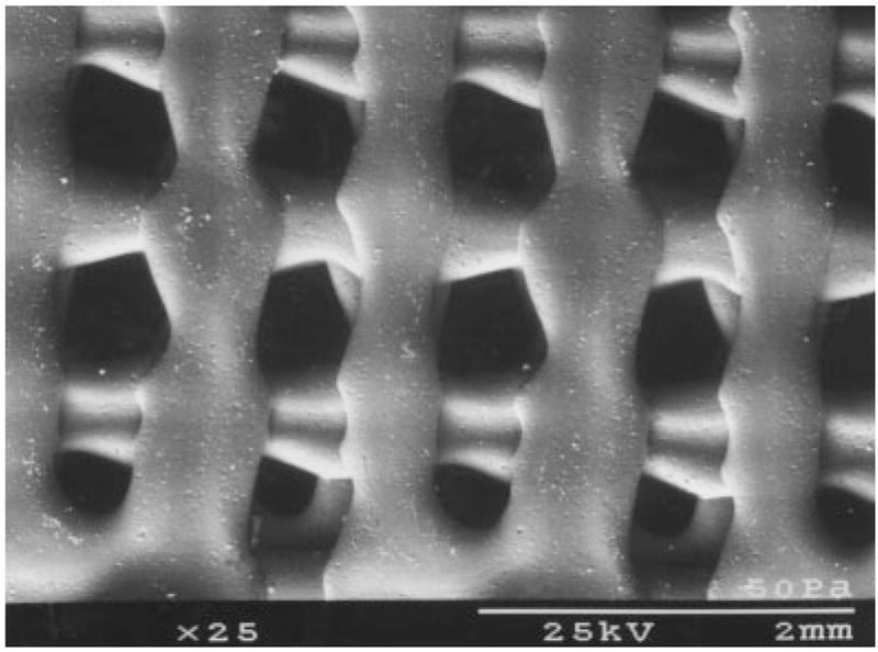
An SEM image of a plain PBT scaffold, showing the shape of the pores.
PBT Scaffold Preparation
The bars of PBT produced as described above were trimmed to make 24 scaffolds that were 0.4 × 0.5 × 0.2 cm. The scaffolds were cleaned in deionized water for 90 min followed by 70% ethanol for 45 min and then finally rinsed in deionized water for 90 min. Scaffolds were allowed to completely dry at room temperature before sterilization in ethylene oxide and implantation.
TCP-Coated Scaffold Preparation (LC-PBT)
A polycaprolactone (PCL) solution was prepared by mixing 5 g of PCL (Fluka Chemika, Switzerland) with 15 g of deionized water and 2.2 g of sodium dodecylsulfate (Fluka Chemika). The solution was placed in a beaker, covered in parafilm, and heated to 75°C for 30 min. Next, it was blended by using a Dremel tool with a sanding disk attachment (Tyler Tool Company, MS) until the solution formed a froth. It was cooled by submerging the beaker in liquid nitrogen and then was allowed to warm to room temperature. The solution was centrifuged at 2.5 × g for 5 min. The supernatant liquid was discarded, and the PCL was rinsed with 15 mL of deionized water. The solution was centrifuged and rinsed four or five times until the resulting supernatant was clear. One final wash was performed with ethanol, and the wet PCL was transferred to a petri dish where it was allowed to dry at room temperature. The dry PCL powder was weighed and blended with β-TCP powder (Fluka Chemika) in a 2:1 (PCL/TCP) ratio. Deionized water was added to make a 30 vol % slurry.
The PCL/TCP slurry was cooled in an ice bath while mixing the solution in an ultrasonic cleaner for 2 min. Plain PBT scaffolds were dipped into the PCL/TCP slurry for approximately 20 s while using the ultrasonic cleaner to remove air bubbles. The slurry-coated scaffolds were allowed to dry for 8 h at room temperature and were then heated to 75°C for 12 h. After the scaffolds cooled to room temperature, they were soaked in deionized water for 90 min and then in 70% ethanol for 45 min and finally rinsed in deionized water for 90 min. Scaffolds were allowed to dry at room temperature (Figure 2). The TCP-coated PBT scaffolds (LC-PBT) were trimmed to 0.4 × 0.5 × 0.2 cm and sterilized in ethylene oxide before implantation. A total of 12 scaffolds were prepared by using this procedure.
Figure 2.
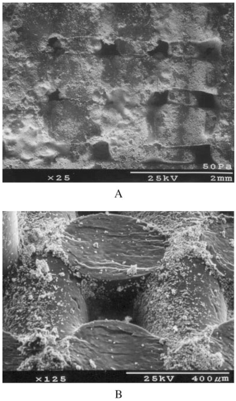
A low magnification (a) and high magnification (b) SEM image of an LC-PBT scaffold, showing the size and shape of TCP particles on the scaffold.
TCP-Impregnated Scaffold Preparation (VI-PBT)
Ten grams of PCL (prepared as described above) and 5 g of TCP were placed inside a mylar bag, heated to 75°C, and mixed into a well-blended soft paste. A plain PBT scaffold was added to the bag, which was placed under vacuum so that the PCL/TCP solution was drawn into the pores of the scaffold. The vacuum-impregnated scaffold was removed from the bag, and excess PCL/TCP was trimmed from the surface. After the scaffolds cooled to room temperature, they were cleaned in deionized water for 90 min, followed by 70% ethanol for 45 min and deionized water for 90 min (Figure 3). Completely dry TCP vacuum-impregnated PBT scaffolds(VI-PBT) were trimmed to 0.4 × 0.5 × 0.2 cm and sterilized in ethylene oxide before implantation. Twelve VI-PBT scaffolds were prepared by using this technique.
Figure 3.
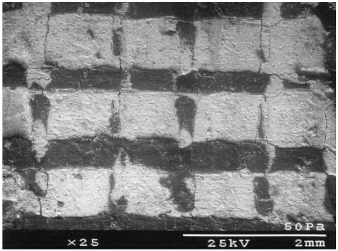
An SEM image of a VI-PBT scaffold, showing the extent to which the pores were filled by TCP particulate.
TGF-β1-Enhanced Scaffold Preparation
Six LC-PBT, six VI-PBT, and 12 plain PBT scaffolds were enhanced by soaking in TGF-β1 (Collaborative Biomedical Products, MA) before implantation. A TGF-β1 solution was prepared by dissolving 2 μg of TGF-β1 in 24 μL of 4 μM HCl. After sterilization, 1/3 μg of TGF-β1 was placed on the bone-interfacing surface of each scaffold. Scaffolds were stored in an incubator at 37°C for 10 h before implantation.
Scaffold Implantation Surgery
The National Institutes of Health (NIH) guide for the care and use of laboratory animals (NIH Publication 85–23 Rev 1985) was followed throughout this study. Four groups of six rats were used to study the bone-bonding characteristics of each group of enhanced and unenhanced plain, LC-PBT, and VI-PBT scaffolds after 4 months in vivo. Surgery for implantation of PBT scaffolds was performed on 120-day-old rats weighing between 0.4 and 0.5 kg. After each rat was anesthetized with 0.03 mL of Torbugesic, followed by an injection containing 0.15 mL of ketamine (20 mg/mL), 0.15 mL of xylene (100 mg/mL), and 0.06 mL of acepromazine (10 mg/mL), an incision was made on the lateral aspect of one randomly selected hind limb. This incision spanned the region of the trochanter to the stifle. An intramuscular plane was separated by using blunt dissection to visualize the femur. Before placing scaffolds, the periosteum was carefully removed at the site with use of a scalpel.
One plain PBT and either one LC-PBT or one VI-PBT scaffold were placed onto the femur. Half of the rats in the study received unenhanced scaffolds, and half received TGF-β1-enhanced scaffolds. All scaffolds were placed on the lateral aspect of the femur. In each animal, a plain PBT scaffold was placed proximal to an LC-PBT or VI-PBT scaffold. The scaffolds were secured to the femur by using circumferentially placed Poly-Vicryl® resorbable sutures (Ethicon, NJ) (Figure 4). The muscles were reopposed, and the skin was closed with subcuticular stitches. All animals recovered without incident and were load bearing within 24 h. The scaffolds were left in vivo for 4 months while the rats were allowed food and water ad libidum. Ten and 3 days before the rats were killed, they were labeled with calcein (Sigma, St. Louis, MO) at a dose of 15 mg/kg.
Figure 4.
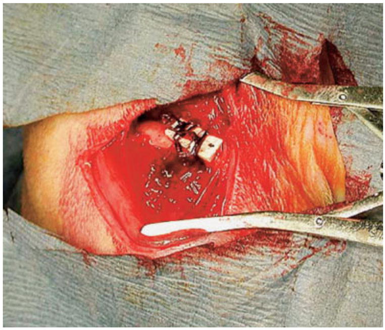
PBT-based scaffolds were initially secured to the lateral surface of a rat femur by using circumferentially placed sutures. [Color figure can be viewed in the online issue, which is available at www.interscience.wiley.com.]
Mechanical Testing
After the rats were killed, both femora were explanted and cleaned of soft tissue (Figure 5). A PBT scaffold and either a LC-PBT or VI-PBT scaffold were glued to the surface of the contralateral femur, in exactly the same position as the scaffolds on the experimental femur, by using epoxy (Ace Quick Set Epoxy, Oak Brook, IL). A uniaxial 120-Ohm strain gauge(Vishay Micro-Measurements, NC) was glued to the surface of each scaffold with epoxy. The gauges were attached to the scaffolds so that the sensing element of each gauge was parallel to the long axis of the bone. Then, the femoral condyle of each sample was potted in a fixture by using a low-melting-point alloy (Cerrobend®, Scottsdale Tool, AZ) that held the specimen perpendicular to the loading pin of a materials testing machine (Series 810 Materials Testing System, MTS Systems Corporation, Minneapolis, MN). Both femora were aligned in a test fixture so that the bone surface with the scaffold was placed completely in tension or compression during loading. The position and alignment of femora varied between tests, but great care was taken to align the femora of each rat to exactly the same position within each test. The femora were loaded six times at a rate of 6.0N/s to a peak load of 4.9N with the scaffold placed in tension while load, stroke, and strain measurements were recorded on a Macintosh G3 computer (Apple Computer, Cupertino, CA). The potting fixture was rotated 180°, and strain values were recorded for six tests while the scaffold was in compression. The strain values at 4.9N were collected and averaged, and the percent differences were calculated by using the formula:
Figure 5.
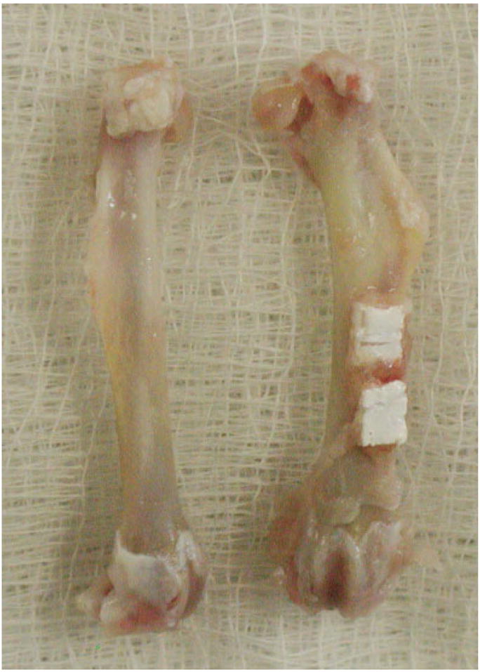
A pair of explanted femora that had been cleaned of soft tissue. Both the experimental (right) and control bones appeared pathology-free after 4 months in vivo. [Color figure can be viewed in the online issue, which is available at www.interscience.wiley.com.]
The percent differences in strain were used as an indicator of the extent of mechanical interlock, which was an indicator of bone ingrowth into the scaffold.23
Scanning Electron Microscopy and Histomorphometry
After cantilever bend testing, the rat femora were dehydrated in ethanol and embedded in polymethylmethacrylate.24 One thick cross section (4 mm) was cut from the center of each surgical site that contained both types of implanted scaffolds for use in BSE. In addition, up to five thin cross-sections (<1 mm) were cut through each scaffold for histomorphometry. The thin sections were ground to a thickness of approximately 10 μm and polished with 0.3 μm of alumina using a Leco GP-25 Grinder/Polisher (Leco Corp, MI). The ground and polished sections were stained by using mineralized bone stain (MIBS) following a published procedure.25 Histomorphometric measurements were collected from each cross section and included the following: total cortical bone area (mm2), bone volume (BV/TV, %), marrow cavity volume (MaV/BV, %), osteoid volume (OV/BV, %), and bone ingrowth fraction (%). Dynamic measurements included mineral apposition rate (MAR, μm/day), adjusted apposition rate (AjAR, μm/day) and bone formation rate (BFR/BS, μm3/μm2/day). Histomorphometry parameters were calculated by using guidelines set forth by the American Society of Bone and Mineral Research.26
Statistical Analysis
Determination of statistical significance for all the parameters that compared the experimental femur with the contralateral control was performed by using a Wilcoxon signed rank test. A Kruskal–Wallis test was used to compare the scaffold types and determine the effects of TGF-β1 enhancement on all mechanical, histological, and histomorphometric parameters. The mechanical test data that gave strains for controls of <10 μstrain were discarded because those strain levels could not be distinguished from noise. In the case where an experimental scaffold gave strain readings <10 μstrain, the scaffold was considered nonbonded. In these cases, the mechanical test data were used in the determination of statistical significance. No histological or histomorphometric data measurements were discarded. All data on individual scaffolds are presented as an average change from the control ± the standard deviation, with the exception of bone ingrowth fraction, which is reported as the actual value ± the standard deviation. Results were considered statistically different at the p < 0.05 level.
RESULTS
Mechanical Testing
Strain transfer measurements through the unenhanced LC-PBT scaffold showed a significantly lower strain transfer than other unenhanced scaffolds (p < 0.05; Figure 6). TGF-β1 enhancement increased the strain transfer through the LC-PBT scaffolds; however, the increase was only significant in compression (p < 0.05). The unenhanced VI-PBT scaffolds showed higher strain transfer than the other unenhanced scaffolds; however, this difference was not significant. The application of TGF-β1 to VI-PBT scaffolds significantly decreased the amount of strain transfer through the scaffold (p < 0.05).
Figure 6.
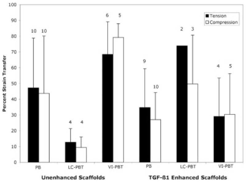
This diagram shows mechanical strain transfer during cantilever bend testing. The white bars indicate compression tests, and black bars indicate tension tests. The TGF-β1-enhanced LC-PBT scaffolds had higher strain transfer than the other enhanced scaffolds ( p < 0.05).
Some mechanical test measurements were not included in the final data analysis. The n for each test is noted above the bar representing the mean strain transfer (Figure 6). One test for an unenhanced PBT and one test for a LC-PBT scaffold were not included in the statistical analysis because the control femur broke during preparation. All remaining tests discarded were discarded because the strain measured from the control scaffold was <10 μstrain.
Electron Microscopy
BSE showed extensive bone growth into the pores of unenhanced [Figure 7(a,b)] and TGF-β1-enhanced [Figure 8(a,b)] PBT and LC-PBT scaffolds. Although almost no bone growth was apparent within the VI-PBT scaffolds, both unenhanced [Figure 7(c)] and TGF-β1-enhanced [Figure 8(c)] VI-PBT scaffolds exhibited bone growth around the scaffolds. TGF-β1 enhancement appeared to cause more extensive bone growth into and around all three types of scaffolds. In particular, BSE images of TGF-β1-enhanced LC-PBT scaffolds showed both bone growth into scaffold pores, as well as some bone growth around the scaffold perimeter [Figure 8(b)].
Figure 7.
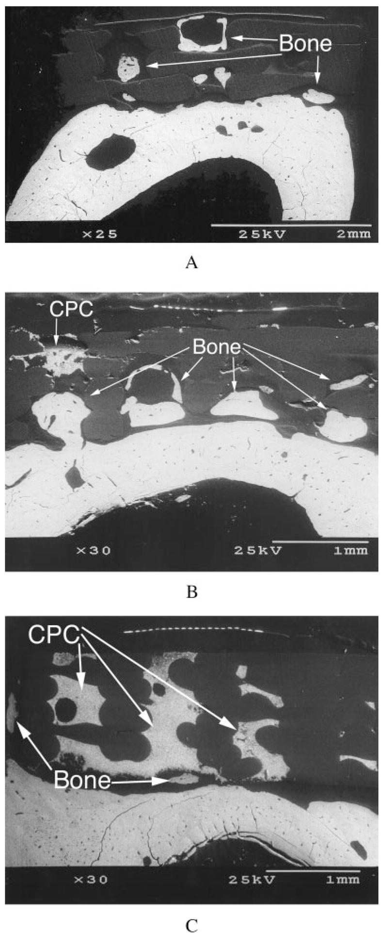
Cross-sectional BSE images of femora showing bone growth into the pores of unenhanced plain PBT (a) and LC-PBT (b) scaffolds, as well as bone growth around the edge of a VI-PBT scaffold (c).
Figure 8.
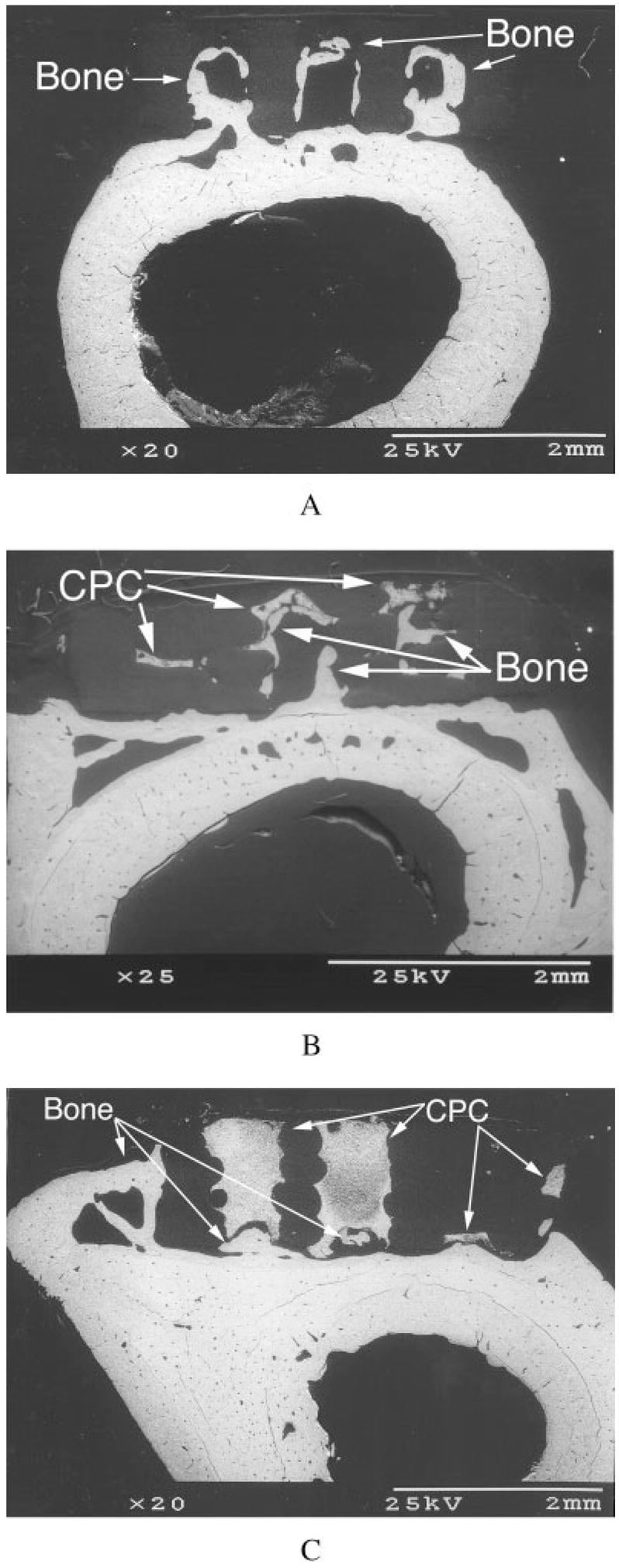
Cross-sectional BSE images of femora showing extensive bone growth into the pores of TGF-β1-enhanced plain PBT (a) and LC-PBT (b) scaffolds. In addition to increased bone growth around the edge of a VI-PBT scaffold (c), TGF-β1 caused bone growth around the edge of the LC-PBT scaffold (b).
Gross Histology
Transmitted light images of scaffold systems showed similar results to those noted from BSE. Bone growth into scaffold pores was prominent in unenhanced [Figure 9(a,b)] and enhanced [Figure 10(a,b)] PBT and LC-PBT scaffolds. Although there was little pore space within the VI-PBT scaffolds, there was extensive bone growth into the available pores. In addition, extensive bone growth was noted around the edges of unenhanced [Figure 9(c)] and enhanced [Figure 10(c)] VI-PBT scaffolds. The TGF-β1-enhanced LC-PBT scaffolds had the most extensive bone growth both into pores and around the scaffold [Figure 10(b)]. TGF-β1 significantly increased the amount of bone growth into the pores of PBT and LC-PBT scaffolds (Table I).
Figure 9.
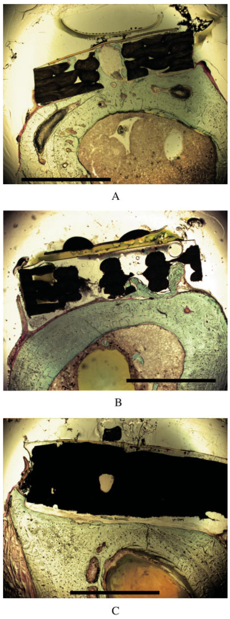
Cross-sectional light micrographs of femora showing bone growth into the pores of unenhanced plain PBT (a) and LC-PBT (b) scaffolds, as well as bone growth around the edge of a VI-PBT scaffold (c). The scale bar is 2 mm.
Figure 10.
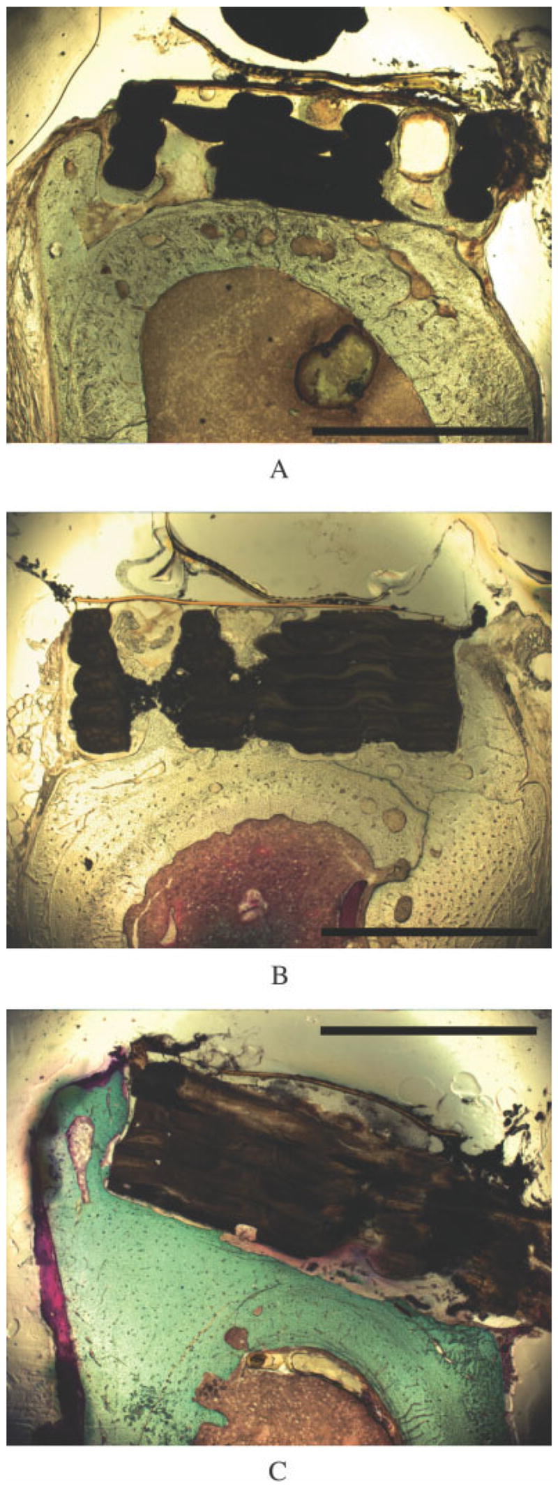
Cross-sectional light micrographs of femora implanted with TGF-β1-enhanced scaffolds show bone formation. Plain PBT (a) and LC-PBT (b) scaffolds showed extensive bone growth into the pores and around the edges of the scaffolds, whereas VI-PBT scaffolds showed bone growth around the scaffold edge (c). The scale bar is 2 mm.
TABLE I.
Average Differences Between the Experimental and Contralateral Control Femur
| Cortical Bone Area (mm2) | BV/TV (%) | MaV/TV (%) | OV/TV (%) | MAR(μm/day) | AjAR(μm/day) | BFR(μm3/μm2/day) | Bone Ingrowth Fraction (%) | |
|---|---|---|---|---|---|---|---|---|
| No TGF-β1 | ||||||||
| PBT | 0.65 ± 0.99* | −0.75 ± 2.53 | 0.28 ± 2.91 | 0.56 ± 0.66* | 0.06 ± 0.19 | 0.26 ± 0.33* | −0.22 ± 0.21* | 21.5 ± 15.0 |
| LC-PBT | 2.53 ± 2.87 | 3.15 ± 3.66 | −3.50 ± 4.19 | 0.36 ± 1.09 | 0.24 ± 0.47 | −0.01 ± 0.16 | −0.08 ± 0.16 | 14.0 ± 14.4 |
| VI-PBT | 0.71 ± 0.67* | 0.44 ± 3.07 | −0.88 ± 2.65 | 0.45 ± 0.67 | −0.65 ± 1.34 | 0.60 ± 0.15 | −0.92 ± 1.09 | 49.4 ± 10.1 |
| TGF-β1 Enhanced | ||||||||
| PBT | 1.41 ± 1.16** | 1.81 ± 3.23 | −2.61 ± 3.18* | 0.92 ± 0.59** | −0.03 ± 0.16 | 0.30 ± 0.19** | −0.33 ± 0.16** | 56.5 ± 12.8 |
| LC-PBT | 2.15 ± 1.46* | 2.03 ± 3.03 | −2.63 ± 2.92 | 0.62 ± 0.45* | 0.25 ± 0.51 | 0.21 ± 0.15* | −0.22 ± 0.28 | 53.6 ± 10.2 |
| VI-PBT | 0.91 ± 1.13 | 1.60 ± 1.90 | −2.26 ± 2.77* | 0.67 ± 1.02 | 0.16 ± .13* | 0.20 ± 0.17* | −0.14 ± 0.13* | 28.1 ± 26.9 |
p < 0.05.
p < 0.01.
The extensive bone growth seen within and around the scaffolds correlated with a significant increase in cortical bone area in unenhanced PBT and VI-PBT scaffolds as well as TGF-β1-enhanced PBT and LC-PBT scaffolds (Table II). Despite the nonsignificant increase in cortical bone area that was noted in unenhanced LC-PBT scaffolds, both unenhanced and enhanced LC-PBT scaffolds had significantly larger increases in cortical bone areas compared with PBT and VI-PBT scaffolds (Table I). Among the scaffolds that displayed a significant increase in cortical bone area, the unenhanced PBT and TGF-β1-enhanced PBT and LC-PBT scaffolds also had a significant increase in osteoid volume. Bone volume generally increased in response to scaffold placement, although the noted increases were not significant.
TABLE II.
Effects of Scaffold Type and TGF-β1 Enhancement on Histology and Histomorphometry Parameters
| BV/TV | MaV/TV | OV/TV | MAR | AjAR | BFR | Cortical Bone Area | Bone Ingrowth Fraction | |
|---|---|---|---|---|---|---|---|---|
| Scaffold type | NS | NS | NS | NS | NS | NS | LC-PBT scaffolds support increased cortical bone area* | NS |
| TGF-β1 enhancement | NS | NS | NS | NS | NS | NS | NS | PBT and LC-PBT scaffolds showed increased bone ingrowth fraction* |
p < 0.05.
Histomorphometry
The only significant increase in MAR that was noted occurred in TGF-β1-enhanced VI-PBT scaffolds (Table II). Although the largest increases in MAR were noted for the LC-PBT scaffolds, these differences were not significant compared with the contralateral control femur (Table II) or compared with the other scaffold types (Table I). The AjAR was significantly increased in all scaffolds except the unenhanced LC-PBT and VI-PBT scaffolds (Table II). Although the BFR was depressed by the scaffolds, the decrease was only significant in PBT scaffolds and TGF-β1-enhanced VI-PBT scaffolds (Table II). Varying the scaffold type or enhancing the scaffolds with TGF-β1 did not significantly affect any of the dynamic histomorphometry parameters (Table I).
DISCUSSION
It was the goal of this study to evaluate various PBT scaffold systems and determine which encouraged the most extensive bone ingrowth while providing a detectable mechanical interlock between the bone and implant. Cantilever bend testing in conjugation with strain gauges were used to assess the degree of strain transfer at the surface of the PBT scaffold. The methods used to evaluate bone growth into the PBT implants included BSE, histology, and histomorphometry.
The systems that provided the highest strain transfer values between the scaffold and bone were the TGF-β1-enhanced LC-PBT and the unenhanced VI-PBT scaffolds. The high-strain transfer noted in the TGF-β1-enhanced LC-PBT scaffolds resulted from extensive bone growth both into the scaffold pores and around the scaffold edges, as was noted in BSE images and histological sections. In contrast to this, BSE images and histological sections of the unenhanced VI-PBT scaffolds showed that the high-strain transfer was mainly a result of bone growth around the sides of the scaffold. Although the unenhanced VI-PBT scaffold did not contain a significant number of pores, the pores that were present often contained bone and may have contributed to some of the strain transfer through these scaffolds.
With the exception of unenhanced VI-PBT scaffolds, the data of at least one scaffold from each test group were discarded because strain readings <10 μstrain were noted on control scaffolds. Control scaffolds whose results were discarded from the data set appeared to be improperly aligned. Because two scaffolds were placed on each femur, it was not always possible to obtain perfect alignment along the bending axis of both scaffolds during each cantilever bend test. In each case, the plain PBT scaffold placed into each animal was used as the guide for alignment. Although using two scaffolds per femur may have introduced variation in the mechanical test results, it reduced effects due to interanimal variability.
Test animals with TGF-β1-enhanced scaffolds were observed to have a greater location/orientation shift between the plain PBT scaffold and either the LC-PBT or VI-PBT scaffold. This was the reason that there were smaller mechanical data sets from TGF-β1 experiments. This may be a reason that the increased strain transfer noted in TGF-β1-enhanced LC-PBT scaffolds was not significant in tension, even though there appeared to be a trend showing this. Overall, the only implant system that provided a poor mechanical interlock between the scaffold and bone was the unenhanced LC-PBT scaffold. Despite the introduction of a possible source of variation by placing two scaffolds on one femur, using a model with two scaffolds greatly increased statistical power by allowing comparison of both the mechanical test results and histologic/histomorphometric data for all LC-PBT and VI-PBT scaffolds with plain PBT scaffolds in the same animal.
In general, the BSE images provided a good indication of bone growth into and around the scaffolds. The only difference noted between the BSE and optical microscopy images was bone growth into porous spaces of the VI-PBT scaffolds. Because there were few spaces in VI-PBT scaffolds, the one section taken for BSE rarely showed bone growth into a pore. However, optical microscopy, which used multiple sections from each scaffold, showed that the few pore spaces available in the VI-PBT scaffolds contained significant amounts of bone. In particular, a higher bone ingrowth fraction was noted in the unenhanced VI-PBT scaffold than in the other unenhanced scaffolds.
Although previous in vivo studies of PBT-based implants indicate that PBT provides a favorable environment for bone formation when blended with polyethylene oxide (PEO),5–8, extensive bone growth was noted into the pores of unenhanced PBT scaffolds. This result may be due to a geometric effect of the pores or the overall shape of the PBT implant, because both variables have been noted to affect bone formation.27,28 In addition, recent in vitro studies indicate that PBT provides a favorable surface for attachment and proliferation of bone marrow cells.15 Our results also suggest that PBT surfaces will support bone growth and attachment.
The histological response to TGF-β1 enhancement of PBT scaffolds is consistent with results of other studies showing that polymers can be used as carriers for growth factors and that in combination they facilitate bone formation. Polymers enhanced with TGF-β1,29 as well BMPs,30,31 have shown increased bone growth. In these experiments, torsional stiffness was significantly increased29,31; however, one of the studies that did further mechanical testing demonstrated that significant differences in stiffness seen in bending are dependant on the direction of the applied load.31 This may explain why no statistically significant differences in strain transfer were noted between plain and enhanced PBT scaffolds in some results of this study.
The significantly increased bone growth noted in LC-PBT scaffolds is in agreement with previous experiments noting improved bone growth into TCP-coated implants.32–36 These studies typically show an increased mechanical interlock, but differences are not always found. One study determined the application of a TCP coating led to increased bone growth without a significant mechanical effect.37
Analysis of the unenhanced VI-PBT scaffolds is consistent with studies showing that a nonporous TCP coating improves bone growth and mechanical attachment of implants.38 In our study, the mechanical interaction of VI-PBT scaffolds appeared to be improved relative to other PBT scaffolds; however, this difference was not significant. This contradiction was likely a result of comparing the VI-PBT scaffold to a porous control, whereas the previous study compared the effect of nonporous TCP coatings to nonporous controls.38 The decreased strain transfer and nonsignificant change in cortical bone area after the TGF-β1 enhancement of VI-PBT scaffolds are contrary to results of previous studies that have investigated the effect of TGF-β1 enhancement of nonporous, TCP-containing implants.39,40 A number of differences between these studies are likely responsible for the discrepancies in these results: 1) the use of metal implants, 2) the use of TCP-containing pastes, and 3) the methods of application of TCP and TGF-β1.
Overall, the PBT scaffold systems tested in this experiment showed that strain sensors attached to these scaffolds can be used to detect mechanical interaction between the bone and scaffold after 4 months in vivo. In addition, there was no visible degradation of the scaffold material during this time period. The detectable strain transfer and slow degradation rate should allow these implants to integrate into surrounding healthy tissue and maintain sufficient mechanical integrity to allow the monitoring of changes in strain transfer throughout the healing period. Furthermore, long-term monitoring of strain transfer through polymer implants may provide a method of measuring implant stability and determining the probability of early implant failure before any such event occurs.
Acknowledgments
The authors thank Brandi Tellis for her assistance with TCP-coated scaffold preparation. Funding was provided by an STTR program grant from the Office of Naval Research. One author (JAS) also acknowledges the support of NIBIB at NIH.
Contract grant sponsor: Office of Naval Research; contract grant number: N00014-00-C-0329
Contract grant sponsor: National Institutes of Health through NIBIB; contract grant number: R01 EB00660
References
- 1.Stevenson S. Enhancement of fracture healing with autogenous and allogeneic bone grafts. Clin Orthop Suppl. 1998;355:S239–S246. doi: 10.1097/00003086-199810001-00024. [DOI] [PubMed] [Google Scholar]
- 2.Pilliar RM. Porous-surfaced metallic implants for orthopedic applications. J Biomed Mater Res. 1987;21(Suppl A1):1–33. [PubMed] [Google Scholar]
- 3.Parsons JR. Resorbable materials and composites. New concepts in orthopedic biomaterials. Orthopedics. 1985;8:907–915. doi: 10.3928/0147-7447-19850701-17. [DOI] [PubMed] [Google Scholar]
- 4.Woodfield TB, Bezemer JM, Pieper JS, van Blitterswijk CA, Riesle J. Scaffolds for tissue engineering of cartilage. Crit Rev Eukaryot Gene Expr. 2002;12:209–236. doi: 10.1615/critreveukaryotgeneexpr.v12.i3.40. [DOI] [PubMed] [Google Scholar]
- 5.Radder AM, Leenders H, van Blitterswijk CA. Interface reactions of PEO/PBT copolymers (Polyactive®) after implantation in cortical bone. J Biomed Mater Res. 1994;28:141–151. doi: 10.1002/jbm.820280202. [DOI] [PubMed] [Google Scholar]
- 6.Radder AM, Leenders H, van Blitterswijk CA. Application of porous PEO/PBT copolymers for bone replacement. J Biomed Mater Res. 1996;30:341–351. doi: 10.1002/(SICI)1097-4636(199603)30:3<341::AID-JBM8>3.0.CO;2-Q. [DOI] [PubMed] [Google Scholar]
- 7.Sakkers RJ, Dalmeyer RAJ, de Wijn JR, van Blitterswijk CA. Use of bone-bonding hydrogel copolymers in bone: An in vitro and in vivo study of expanding PEO-PBT copolymers in goat femora. J Biomed Mater Res. 2000;49:312–318. doi: 10.1002/(sici)1097-4636(20000305)49:3<312::aid-jbm3>3.0.co;2-e. [DOI] [PubMed] [Google Scholar]
- 8.van Blitterswijk CA, van den Brink J, Leenders H, Bakker D. The effect of PEO ratio on degradation, calcification and bone-bonding of PEO/PBT copolymer (Polyactive®) Cells Mater. 1993;3:23–36. [Google Scholar]
- 9.Sakkers RJB, de Vijn JR, Dalmeyer RAJ, Brand R, van Blitterswijk CA. Evaluation of copolymers of polyethylene oxide and polybutylene terephthalate (Polyactive®): Mechanical behaviour. J Mater Sci Mater Med. 1998;9:375–379. doi: 10.1023/a:1013227428530. [DOI] [PubMed] [Google Scholar]
- 10.Claase MB, Grijpma DW, Mendes SC, De Bruijn JD, Feijen J. Porous PEOT/PBT scaffolds for bone tissue engineering: preparation, characterization, and in vitro bone marrow cell culturing. J Biomed Mater Res. 2003;64A:291–300. doi: 10.1002/jbm.a.10418. [DOI] [PubMed] [Google Scholar]
- 11.Liu Q, de Wijn JR, van Blitterswijk CA. Composite biomaterials with chemical bonding between hydroxyapatite filler particles and PEG/PBT copolymer matrix. J Biomed Mater Res. 1998;40:490–497. doi: 10.1002/(sici)1097-4636(19980605)40:3<490::aid-jbm20>3.0.co;2-m. [DOI] [PubMed] [Google Scholar]
- 12.Risbud M, Saheb DN, Jog J, Bhonde R. Preparation, characterization and in vitro biocompatibility evaluation of poly(butylene terephthalate)/wollastonite composites. Biomaterials. 2001;22:1591–1597. doi: 10.1016/s0142-9612(00)00325-2. [DOI] [PubMed] [Google Scholar]
- 13.Roessler M, Wilke A, Griss P, Kienapfer H. Missing osteoconductive effect of a resorbable PEO/PBT copolymer in human bone defects: A clinically relevant pilot study with contrary results to previous animal studies. J Biomed Mater Res (AB) 2000;53:167–173. doi: 10.1002/(sici)1097-4636(2000)53:2<167::aid-jbm6>3.0.co;2-j. [DOI] [PubMed] [Google Scholar]
- 14.Vaidyanathan R, Walish J, Lombardi JL, Kasichainula S, Calvert P, Cooper KC. The extrusion freeforming of functional ceramic prototypes. J Metals. 2000;52:34–37. [Google Scholar]
- 15.Olde Riekerink MB, Claase MB, Engbers GH, Grijpma DW, Feijen J. Gas plasma etching of PEO/PBT segmented block polymer films. J Biomed Mater Res. 2003;65A:417–428. doi: 10.1002/jbm.a.10520. [DOI] [PubMed] [Google Scholar]
- 16.Hollister SJ, Maddox RD, Taboas JM. Optimal design and fabrication of scaffolds to mimic tissue properties and satisfy biological constraints. Biomaterials. 2002;23:4095–4103. doi: 10.1016/s0142-9612(02)00148-5. [DOI] [PubMed] [Google Scholar]
- 17.Meredith N. A review of nondestructive test methods and their application to measure the stability and osseointegration of bone anchored endosseous implants. Crit Rev Biomed Eng. 1998;26:275–291. doi: 10.1615/critrevbiomedeng.v26.i4.20. [DOI] [PubMed] [Google Scholar]
- 18.Bergmann G, Graichen F, Rohlmann A. Hip joint forces in sheep. J Biomech. 1999;32:769–777. doi: 10.1016/s0021-9290(99)00068-8. [DOI] [PubMed] [Google Scholar]
- 19.Bergmann G, Deuretzbacher G, Heller M, Graichen F, Rohlmann A, Strauss J, Duda GN. Hip contact forces and gait patterns from routine activities. J Biomech. 2001;34:859–871. doi: 10.1016/s0021-9290(01)00040-9. [DOI] [PubMed] [Google Scholar]
- 20.Rohlmann A, Arntz U, Graichen F, Bergmann G. Loads on an internal spinal fixation device during sitting. J Biomech. 2001;34:989–993. doi: 10.1016/s0021-9290(01)00073-2. [DOI] [PubMed] [Google Scholar]
- 21.Rohlmann A, Graichen F, Weber U, Bergmann G. Monitoring in vivo implant loads with a telemeterized internal spinal fixation device. Spine. 2000;25:2981–2986. doi: 10.1097/00007632-200012010-00004. [DOI] [PubMed] [Google Scholar]
- 22.Rohlmann A, Bergmann G, Graichen F. Loads on internal spinal fixators measured in different body positions. Eur Spine J. 1999;8:354–359. doi: 10.1007/s005860050187. [DOI] [PMC free article] [PubMed] [Google Scholar]
- 23.Battraw GA, Miera V, Anderson PL, Szivek JA. Bilateral symmetry of biomechanical properties in rat femora. J Biomed Mater Res. 1996;32:285–288. doi: 10.1002/(SICI)1097-4636(199610)32:2<285::AID-JBM19>3.0.CO;2-I. [DOI] [PubMed] [Google Scholar]
- 24.Emmanual J, Hornbeck C, Bloebaum RD. A polymethylmethacrylate method for large specimens of mineralized bone with implants. Stain Technol. 1987;62:401–410. doi: 10.3109/10520298709108030. [DOI] [PubMed] [Google Scholar]
- 25.Villanueva AR, Lundin KD. A versatile new mineralized bone stain for simultaneous assessment of tetracyline and osteoid seams. Stain Technol. 1989;64:129–138. doi: 10.3109/10520298909106985. [DOI] [PubMed] [Google Scholar]
- 26.Parfitt AM, Drezner MK, Glorieux FH, Kanis JA, Malluche H, Meunier PJ, Ott SM, Recker RR. Bone histomorphometry: Standardization of nomenclature, symbols, and units. J Bone Miner Res. 1987;2:595–599. doi: 10.1002/jbmr.5650020617. [DOI] [PubMed] [Google Scholar]
- 27.Tsuruga E, Takita H, Itoh H, Wakisaka Y, Kuboki Y. Pore size of porous hydroxyapatite as the cell-substratum controls BMP-induced osteogenesis. J Biochem. 1997;121:317–324. doi: 10.1093/oxfordjournals.jbchem.a021589. [DOI] [PubMed] [Google Scholar]
- 28.van Eeden SP, Ripamonti U. Bone differentiation in porous hydroxyapatite in baboons is regulated by the geometry of the substratum: Implications for reconstructive craniofacial surgery. Plast Reconstr Surg. 1994;93:959–966. doi: 10.1097/00006534-199404001-00010. [DOI] [PubMed] [Google Scholar]
- 29.Schmidmaier G, Wildemann B, Bail H, Lucke M, Fuchs T, Stemberger A, Flyvbjerg A, Haas NP, Raschke M. Local application of growth factors (insulin-like growth factor-1 and transforming growth factor-beta1) from a biodegradable poly(D,L-lactide) coating of osteosynthetic implants accelerates fracture healing in rats. Bone. 2001;28:341–350. doi: 10.1016/s8756-3282(00)00456-7. [DOI] [PubMed] [Google Scholar]
- 30.Miyamoto S, Takaoka K, Okada T, Yoshikawa H, Hashimoto J, Suzuki S, Ono K. Polylactic acid-polyethylene glycol block copolymer. A new biodegradable synthetic carrier for bone morphogenetic protein. Clin Orthop. 1993;294:333–343. [PubMed] [Google Scholar]
- 31.Sandhu HS, Kanim LE, Kabo JM, Toth JM, Zeegan EN, Liu D, Seeger LL, Dawson EG. Evaluation of rhBMP-2 with an OPLA carrier in a canine posterolateral (transverse process) spinal fusion model. Spine. 1995;20:2669–2682. doi: 10.1097/00007632-199512150-00008. [DOI] [PubMed] [Google Scholar]
- 32.Soballe K, Hansen ES, Brockstedt-Rasmussen H, Pedersen CM, Bunger C. Bone graft incorporation around titanium-alloy- and hydroxyapatite-coated implants in dogs. Clin Orthop. 1992;274:282–293. [PubMed] [Google Scholar]
- 33.Soballe K, Hansen ES, Brockstedt-Rasmussen H, Hjortdal VE, Juhl GI, Pedersen CM, Hvid I, Bunger C. Gap healing enhanced by hydroxyapatite coating in dogs. Clin Orthop. 1991;272:300–307. [PubMed] [Google Scholar]
- 34.Chae JC, Collier JP, Mayor MB, Surprenant VA, Dauphinais LA. Enhanced ingrowth of porous-coated CoCr implants plasma-sprayed with tricalcium phosphate. J Biomed Mater Res. 1992;26:93–102. doi: 10.1002/jbm.820260109. [DOI] [PubMed] [Google Scholar]
- 35.Cook SD, Thomas KA, Dalton JE, Volkman TK, Whitecloud TS, III, Kay JF. Hydroxylapatite coating of porous implants improves bone ingrowth and interface attachment strength. J Biomed Mater Res. 1992;26:989–1001. doi: 10.1002/jbm.820260803. [DOI] [PubMed] [Google Scholar]
- 36.Cook SD, Baffes GC, Palafox AJ, Wolfe MW, Burgess A. Torsional stability of HA-coated and grit-blasted titanium dental implants. J Oral Implant. 1992;18:354–365. [PubMed] [Google Scholar]
- 37.Sumner DR, Turner TM, Urban RM, Turek T, Seeherman H, Wozney JM. Locally delivered rhBMP-2 enhances bone ingrowth and gap healing in a canine model. J Orthop Res. 2004;22:58–65. doi: 10.1016/S0736-0266(03)00127-X. [DOI] [PubMed] [Google Scholar]
- 38.Chae JC, Collier JP, Mayor MB, Surprenant VA. Efficacy of plasma-sprayed tricalcium phosphate in enhancing the fixation of smooth titanium intramedullary rods. Ann N Y Acad Sci. 1988;523:81–90. doi: 10.1111/j.1749-6632.1988.tb38502.x. [DOI] [PubMed] [Google Scholar]
- 39.Lind M, Overgaard S, Ongpipattanakul B, Nguyen T, Bunger C, Soballe K. Transforming growth factor-beta 1 stimulates bone ongrowth to weight-loaded tricalcium phosphate coated implants: An experimental study in dogs. J Bone Joint Surg. 1996;78:377–382. [PubMed] [Google Scholar]
- 40.Ongpipattanakul B, Nguyen T, Zioncheck TF, Wong R, Osaka G, DeGuzman L, Lee WP, Beck LS. Development of tricalcium phosphate/amylopectin paste combined with recombinant human transforming growth factor beta 1 as a bone defect filler. J Biomed Mater Res. 1997;36:295–305. doi: 10.1002/(sici)1097-4636(19970905)36:3<295::aid-jbm4>3.0.co;2-9. [DOI] [PubMed] [Google Scholar]


